Create Home Automation with Arduino IoT Cloud
By Rafik Mitry, Mouser Electronics
Published June 17, 2020
I was always inspired to live in a smart home where I can automate some of the everyday tasks to make life easier and comfortable. For example, how many times does your TV remote disappear, and you just wish to say a voice command to do the task for you instead? Many Smart TVs do this already, of course, but buying a good one can be a bit expensive. In this project, I describe how easy it is to make some of your home appliances smart with an Arduino board. Besides controlling the TV with voice, I will use a temperature sensor, motion sensor, and an RGB LED to demonstrate the Arduino MKR WiFi 1010 capabilities. I will also connect the Arduino board to an Amazon Alexa device, and then you can set up some routines for your home automation.
Project Materials and Resources
Access the project's BOM on Mouser's website for the required component:
- 782-ABX00023: Arduino MKR WiFi 1010
- 700-DS18B20+: Maxim integrated DS18B20 digital thermometer
- 485-189: Adafruit PIR Motion Sensor
- 604-WP154A43VBDZGWCA: Kingbright RGB LED
- 78-TSSP98038: Infrared Receiver 38kHz
- 720-SFH4546: Infrared Emitters - High Power Infrared 940nm
- 610-2N2222A: 2N2222A BJT NPN transistor
- 756-MFR4-470RFI: 470 ohm Metal Film Resistors - Through Hole 1% 0.5W
- 594-MBE04140C4701FC1: 4.7Kohm Metal Film Resistors - Through Hole 1% 1watt
- 660-MF1/4LCT52R271G: 270 ohm Metal Film Resistors - Through Hole 2% 1/4watt (3 pcs)
- 932-MIKROE-513: Jumper Wires WIRE JUMPER MALE TO MALE 15CM 10PK
- 474-PRT-12002: SparkFun accessories breadboard - self-adhesive (White)
Software:
- Arduino IoT Cloud
- Arduino Alexa Skill
- IFTTT (If This Then That)
Project Technology Overview
For this project, we've used the following products and technologies, described in the following sections:
Arduino MKR WiFi 1010
Arduino MKR WiFi 1010 is designed to quickly and easily enable WiFi connectivity for any Internet of Things application. It is powered by the Microchip Technology SAMD21 Cortex-M0+ 32bit Low Power Arm® Microcontroller (MCU) and features a U-BLOX NINA-W10 Series module, offering 2.4GHz IEEE® 802.11 b/g/n WiFi. The Arduino MKR WiFi 1010 includes the ECC508 CryptoAuthentication™ IC ensuring secure communication using SHA-256 encryption. The board has a USB port that can be used to supply power (5V). Also, the MKR WiFi board has a lithium polymer (Li-Po) charging circuit that allows the board to run on battery power. Switching from one source to another is done automatically. (Figure 1)
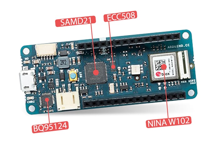
Figure 1: Arduino MKR WiFi 1010 PinOut (Source: Mouser Electronics)
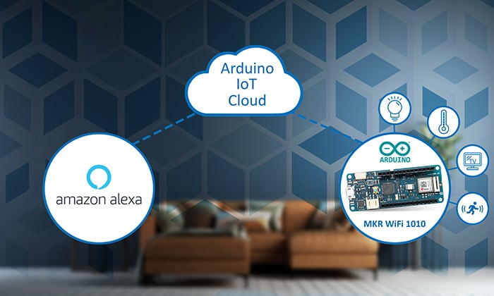
Arduino IoT Cloud
The Arduino IoT Cloud enables a fast and straightforward way to connect your board to the Cloud with ensuring secure communications. Using the Arduino Cloud, you can log, monitor, and analyze sensor data. It can also be used to trigger events and automate your home appliances.
The Arduino IoT Cloud has four main components (Figure 2):
- Hardware devices to collect data or control something
- Software to define the behavior of the hardware
- Cloud application to store data or remotely control the hardware
- An online dashboard to view and manage your devices
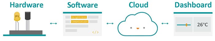
Figure 2: Arduino IoT Cloud main components (Source: Arduino)
The project flow and component definitions are shown below:
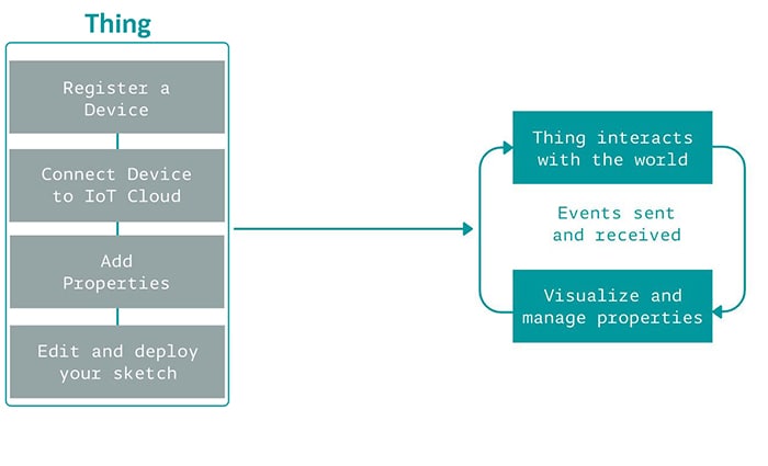
Figure 3: Arduino IoT Cloud project flow (Source: Arduino)
Thing: Things represent the inherent properties of the object, with as little reference to the actual hardware used to implement them. Each thing is represented by a collection of properties (e.g., temperature, light). (Source: Arduino)
Properties: Properties are the qualities defining the characteristics of a system. A property can be something like a 'read-only' (RO) setting to indicate the Arduino IoT Cloud can read the data, but cannot change the value of the property. A property might be designed as 'read and write' (RW) if the Arduino IoT Cloud can also remotely change the property's value and send an event notification to the device. (Source: Arduino)
Events: The Arduino IoT Cloud becomes aware of events when it receives application messages that indicate something has happened. For example, it might be informed by a face-recognition application that someone is at a door, or it has received a request from another app that light has to be turned on. (Source: Arduino)
Software Setup
The first requirement is to set up the Arduino MKR WiFi 1010 board with the Arduino IoT Cloud.
- Navigate to the Arduino Create website
- Click on the Getting Started button. (Figure 4)

Figure 4: Arduino Create website (Source: Mouser Electronics)
- Choose the Arduino MKR WiFi 1010 board and click on Set up. (Figure 5)
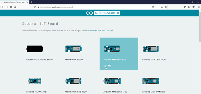
Figure 5: Arduino Create website – Setting up the Arduino MKR WiFi board (Source: Mouser Electronics)
- To be able to flash the board using the Arduino web editor, you will need to download and install the Arduino Create Plugin. Follow the installation by clicking Next.
- After you reach step five in the installation process, you will be able to upload your first sketch. First, you will have to enter your WIFI data. Click on the Enter WiFi data button. (Figure 6)
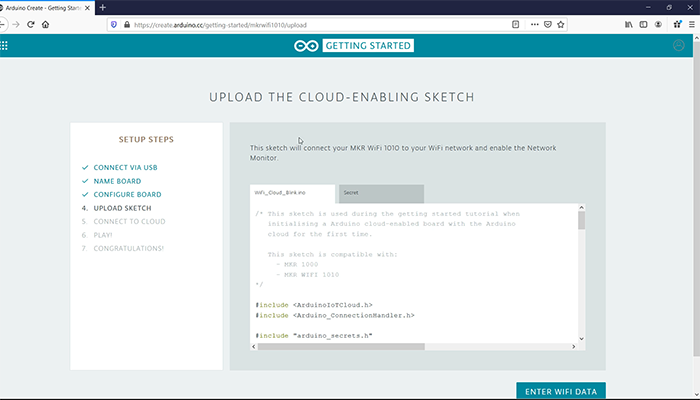
Figure 6: Arduino Create website – Setting up the Arduino MKR WiFi board (Source: Mouser Electronics)
- Click on Upload
- After the upload is completed, you will be able to toggle the built-in LED on the Arduino board by entering On or Off command in the Network Monitor.
Now we are ready to start with setting up our Thing and Properties in the Arduino IoT Cloud.
Arduino IoT Cloud
Navigate back to the main page of the Arduino Create website and click on the Arduino IoT Cloud button.
- Click on the Add new thing button
- Enter a name for your Thing and select the device that will be associated with your Thing. In our case here, we will choose the MKR WiFi 1010.
- Let's add our properties. You can add up to five properties in the free plan that Arduino offers.
Click on the ADD PROPERTY button.- Temperature
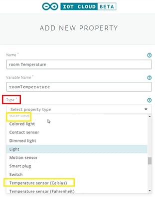
Figure 7: Adding a property in the Arduino IoT (Source: Mouser Electronics)
- Give your property a name
- Choose the Type of your property. Under the Smart Home section, choose Temperature Sensor Celsius. (Figure 7)
- For the permission, set it as Read only and choose When the value changes for the Update. We want that the Cloud only receive values from the MKR when the temperature changes.
- Finally, click on add property.
- Motion Sensor
- Give your property a name
- Choose the Type of your property. Under the Smart Home section, choose Motion sensor.
- For the update function, choose 'When the value changes'.
- Finally, click on add property.
- Colored Light
- Give your property a name
- Choose the Type of your property. Under the Smart Home section, choose Colored light.
- For the permission, set it as Read & Write and choose When the value changes for the Update. That way, we can control the light behavior (color and brightness).
- Finally, click on add property.
- TV
- Give your property a name
- Choose the Type of your property. Under the Smart Home section, choose TV.
- For permission, set it as Read & Write and choose When the value changes for the Update—that way, we can control the TV (power, volume, and switching channels).
- Finally, click on add property.
- Temperature
Now, you should have something similar, looking like the table in Figure 8.
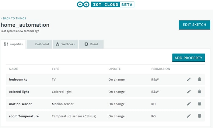
Figure 8: Properties table in the Arduino IoT Cloud (Source: Mouser Electronics)
Hardware Setup
In this section, I will walk you through the assembly of all hardware parts. But before we start with connecting all the main components, we will use the Arduino and the IR receiver to read the TV remote control IR codes so that we will be able later to send the IR codes using the Arduino.
Connect the output pin of the receiver to PIN 11 on the Arduino, GND to GND, and Vs to 5V. (Figure 9)
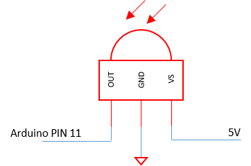
Figure 9: IR receiver circuit (Source: Mouser Electronics)
- Flash the IRrecv code by Ken Shirriff to the Arduino board.
- Open the Serial monitor
- Point the TV remote controller to the receiver and press the following buttons:
- POWER
- CHANNELS FROM 1 TO 3
- VOLUME UP
- VOLUME DOWN
- MUTE
- CHANNEL UP
- CHANNEL DOWN
- For each press, you'll receive an array of unsigned integers. Copy the array to a notepad and add the variable name to it. Here's an example of a Samsung's TV remote when pressing the power button:
unsigned int onoff[RAW_DATA_LEN]= {4600,4600, 600,1700, 550,1700, 600,1700, 600,550, 650,500, 550,550, 600,600, 650,450, 600,1700, 600,1700, 550,1700, 600,550, 600,550, 600,550, 600,550, 600,550, 550,600, 550,1700, 600,550, 600,550, 600,550, 600,550, 550,600, 550,550, 600,1700, 600,550, 600,1700, 550,1700, 600,1700, 600,1700, 600,1650, 600,1700, 600};
After you have copied all the IR codes needed, you can disconnect the IR receiver and connect all the main components to the Arduino MKR WiFi 1010. (Figure 10)

Figure 10: Circuit diagram for the hardware setup (Source: Mouser Electronics)
- Maxim integrated DS18B20 digital thermometer:
- Connect the Ground pin of the sensor to the GND pin of the Arduino MKR WiFi board
- Connect the DQ pin of the sensor to pin 5 (Arduino MKR WiFi)
- Add a 4.7kΩ resistor between the DQ pin and VDD pin of the sensor
- Connect the VDD pin to the 5V (Arduino MKR WiFi)
The sensor can be supplied with voltages between 3V and 5.5V.
- Adafruit PIR Motion Sensor:
- Connect the Ground pin of the sensor to the GND pin of the Arduino MKR WiFi board
- Connect the Digital out pin to pin 1 (Arduino MKR WiFi)
- Connect the VDD pin to the 5V (Arduino MKR WiFi)
- Colored Light:
- Connect the red pin leg (RGB LED) with a 270Ω in series to pin 4 (Arduino MKR WiFi)
- Connect the green pin leg (RGB LED) with a 270Ω in series to pin 3 (Arduino MKR WiFi)
- Connect the blue pin leg (RGB LED) with a 270Ω in series to pin 2 (Arduino MKR WiFi)
- Connect the Anode (longest leg of the RGB LED) to the 5V power supply (Arduino MKR WiFi)
NOTE: If you are using a common cathode, connect the cathode to the GND pin instead of the 5V.
- IR emitter:
The output pin of an Arduino cannot supply sufficient current to drive an IR LED. Therefore, we implemented here a driver circuit using an NPN transistor and a 470Ω resistor. (Figure 11)
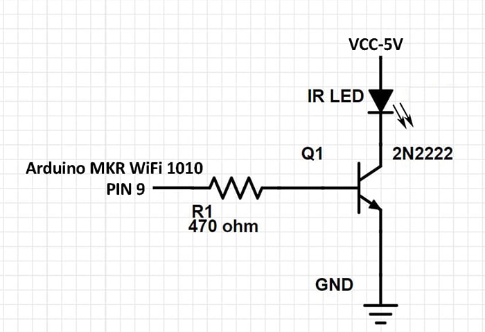
Figure 11: IR LED driver circuit (Source: Mouser Electronics)
Arduino Web Editor
Now that everything is set up download the 'home_automation' project, which is available on Mouser GitHub repository.
- Connect you're the board to a PC and make sure the Arduino Create Plugin is running in the background.
- Navigate to the Thing you created (Figure 8) on the Arduino Create website
- Click on the Edit sketch button.
- In the web editor, you will see your .ino file that you will need to edit. You can copy/paste the home_automation.ino sketch that is provided in our GitHub repository, but make sure to modify the variables names, in case you changed the ones we're using in this tutorial.
- Navigate to the Secret tab and enter your WiFi SSID and password.
- Click on the Upload and Save Button
- After the flashing process is completed, click on the Go to IoT cloud button. From there, you will be able to access your dashboard.
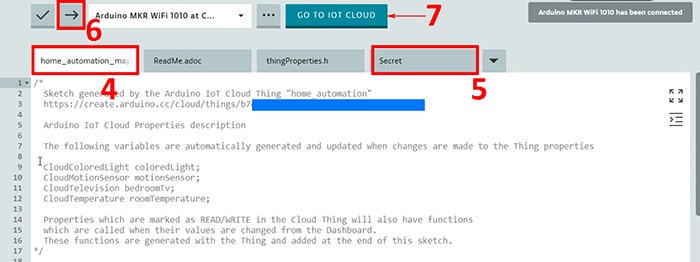
Figure 12: Flashing the Arduino MKR WiFi 1010 using the Arduino Web Editor (Source: Mouser Electronics)
Your dashboard should look like the following screenshot. (Figure 13)
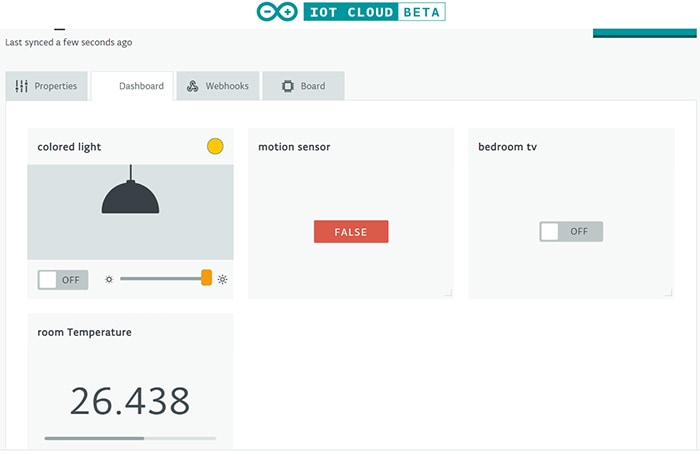
Figure 13: Arduino IoT Cloud dashboard (Source: Mouser Electronics)
Arduino Alexa Skill
Arduino offers another great feature, which is the integration of your Arduino MKR WiFi board with the Amazon Alexa device. In this section, I will walk you through the steps of linking your board with the Alexa app.
- Open the Amazon Alexa app on your smartphone.
- Navigate to the Skills & Games section.
- Search for the Arduino skill and click on activate
- You will be navigated to the Arduino website, where you will have to log in to link your Arduino account to the Amazon Alexa account.
- After the activation is completed, Alexa will automatically ask if you want to discover new devices. Click on the Discover Devices. This action will take up to 45 seconds.
- Finally, you'll be able to see the devices added to the Alexa app. (Figure 14)
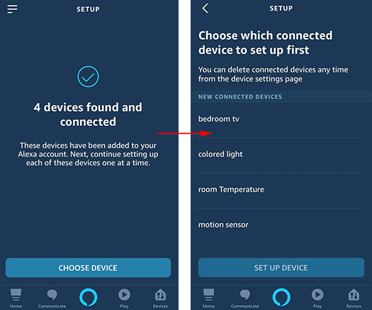
Figure 14: Integration of the Arduino MKR WiFi 1010 to Alexa (Source: Mouser Electronics)
Alexa commands:
I will add here some of the Alexa commands for the added devices.
TV:
- Alexa, turn on the bedroom tv.
- Alexa, turn the bedroom tv volume up.
- Alexa, mute the bedroom tv.
- Alexa, change the channel to 3.
Colored light:
- Alexa, turn on colored light.
- Alexa, change colored light to blue
Room temperature:
- Alexa, what's the room temperature.
IFTTT
In this section, I will show how to get notified on your mobile device when motion is detected. For this, I'll be using the IFTTT (If this then that) service. The Arduino IoT Cloud offers the support to integrate the IFTTT service very quickly.
- Navigate to the IFTTT website and log in or sign up if you don't already have an account
- Click on your profile picture in the upper right-hand corner
- Click on Create from the dropdown menu
- Click on the Plus logo and search for Webhooks. Choose Receive a web request as the trigger
- Enter the event name that will trigger the webhook. The event name will be the motion sensor variable, which we have defined as a property in the Arduino IoT Cloud.
- Click on Create Trigger and then click on the Plus logo to choose the action
- Search for Notifications and choose to Send a notification from the IFTTT app
- In the message field, change '{{EventName}}' to the name you prefer.
- Add these two parameters to the text box {{Value2}} - {{OccurredAt}}. 'Value2' will tell you the state of the motion detector.
- Finally, click on Create Action followed by Finish
Activating the IFTTT service on the Arduino IoT Cloud
- On the IFTTT website, click on your profile picture in the upper right-hand corner
- Click on My services and choose Webhooks
- In the right upper right-hand corner, click on Documentation
Add your motion sensor variable instead of the '{event}' inside the POST or GET web request link. Then copy that link. (Figure 15)
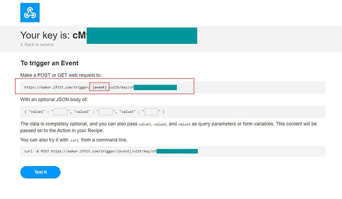
Figure 15: IFTTT webhook link (Source: Mouser Electronics)
- Navigate to the Thing you created (Figure 8) on the Arduino Create website and click on the Webhooks tab.
- Paste the webhook link you copied from IFTTT into the Arduino IoT Cloud. (Figure 16)
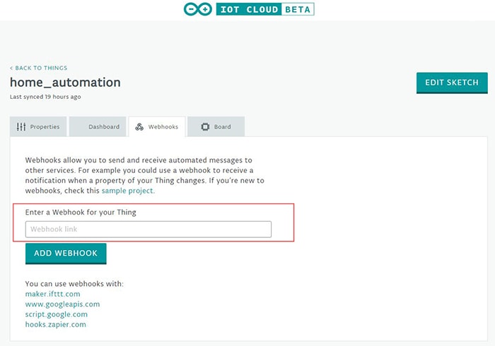
Figure 16: Adding the webhook link to the Arduino IoT Cloud (Source: Mouser Electronics)
- Finally, click on ADD WEBHOOK
The final step is to download the IFTTT mobile app, which is available for Android and iOS. Log in to the IFTTT mobile app using the same account, which you used to create the webhook service. Now, whenever your motion sensor variable gets triggered, you'll receive a notification.
Here is the final look of the project with all sensors built-in and added with the board in a 3D printed box. The .stl file for the 3D printed box you can find it on the Mouser GitHub repository.
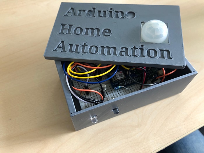
Figure 17: Sensors and board added into a 3D printed box (Source: Mouser Electronics)
Conclusion
This project created different home automation applications that show how easy it is to build your own smart home. Using the Arduino MKR WiFi 1010 makes it very easy to connect to the Arduino IoT Cloud and start sending data to the cloud. With the help of an Amazon Alexa device, you can easily control the devices that are connected to the Arduino board with voice commands. Besides, you can set up these devices with routines that will make your life a bit easier.