No-Code/Low-Code Hardware Prototyping with Analog Devices

Image Source: Tahsin/Stock.adobe.com; generated with AI
By Michael Parks, PE, for Mouser Electronics
Published October 14, 2024
Introduction
The Analog Devices AD-SWIOT1L-SL (Figure 1 and Figure 2) is a development platform designed to help engineers prototype intelligent and secure devices that can connect to a network. The kit is ideal for use in industrial field environments and includes everything needed to get started, including the hardware itself, enclosure, cables, and software.

Figure 1: The AD-SWIOT1L-SL from Analog Devices is a power development platform for connected industrial applications. (Source: Mouser Electronics)
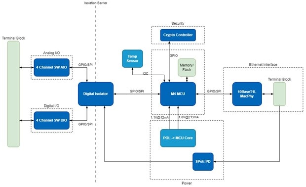
Figure 2: Block diagram of the AD-SWIOT1L-SL (Source: Analog Devices)
The AD-SWIOT1L-SL connects to a network using Single Pair Ethernet (SPE), which transmits data using a single twisted pair of wires. This makes it ideal for industrial environments where space may be limited. The kit includes a 10BASE-T1L-to-USB adapter board that allows users to connect the AD-SWIOT1L-SL to a computer for development.
The AD-SWIOT1L-SL platform is compatible with the Analog Devices Scopy software toolset to configure the device and visualize data. Scopy is a versatile and powerful software application designed to work with various Analog Devices hardware platforms. It is primarily used for signal analysis, data visualization, and debugging in the laboratory. Scopy provides a graphical user interface (GUI) that enables users to interact with hardware devices such as oscilloscopes, signal generators, and logic analyzers to simplify the process of capturing and analyzing signals. It also provides a way to upload JavaScript code to the device under test to perform rudimentary programming of the GPIO pins, which we will use in this demonstration project.
Scopy offers several key features:
- GUI: Scopy's GUI makes it easy to control and visualize the data from the AD-SWIOT1L-SL. The intuitive design allows users to quickly set up and perform measurements, view waveforms, and analyze signals.
- Software-defined oscilloscope: Scopy enables the AD-SWIOT1L-SL to function as a dual-channel oscilloscope with features such as triggering, time base adjustment, and various display modes.
- Digital I/O: The software can control and monitor the AD-SWIOT1L-SL's digital input and output pins, making it useful for digital signal analysis and logic testing.
- Flexibility and customization: The software supports scripting and automation, allowing users to create custom measurement setups and automate repetitive tasks. This feature is beneficial for more advanced users who need to perform complex analyses.
- Cross-platform compatibility: Scopy is available for multiple operating systems, including Windows, macOS, and Linux, ensuring broad accessibility for users with different computing environments.
The combination of Scopy and the AD-SWIOT1L-SL platform provides a powerful and flexible toolset for prototyping process control and industrial automation solutions. Additionally, the tools offer excellent educational and experimentation resources for students, educators, and hobbyists.
In this project, we will use the AD-SWIOT1L-SL development board, two non-contact water sensors, and a water pump to maintain a tank with the proper liquid level. When the lower sensor no longer detects water (i.e., the low-level state has been reached inside the tank), the pump will trigger and let water into the tank until the upper sensor detects water (i.e., the high-level state has been reached inside the tank).
Bill of Materials and Tools
As of the publication date, the total BOM (Table 1) costs approximately US$450.00 before shipping and taxes.
Table 1. Bill of materials
|
Mouser Part Number |
Part Description |
QTY |
|---|---|---|
|
Analog Devices AD-SWIOT1L-SL Development Platform |
1 |
|
|
XP Power 24V DC Power Supply, 2A output |
1 |
|
|
DF Robot Non-Contact Water Sensor |
2 |
|
|
Adafruit Power Relay FeatherWing |
1 |
To complete this project, you will also need to access the project's GitHub repository.
In addition to the BOM, you will need the following tools:
- Water tank (required)
- Water pump, 24VDC, up to 2A (required)
- Adhesives such as hot glue
- Small Phillips and flathead screwdrivers
- Wire cutter/stripper
- Scissors
- Heat shrink tube
- Small needle nose pliers
- Digital multimeter
- High-speed internet connection, Windows 10 PC or newer (required)
Hardware Build
The Analog Devices AD-SWIOT1L-SL development platform is powered by the MAX32650 low-power Arm® Cortex®-M4 microcontroller with 128MB of external RAM and 8MB of external flash memory. Security features are enabled by the MAXQ1065 security coprocessor. The board also incorporates the AD74413R quad-channel, software-configurable input and output, and the MAX14906 quad-channel industrial digital output/digital input ICs, allowing the multiplexing of several analog and digital functions on four channels, which can be independently configurable through software to act as:
- Current output or input
- Voltage output or input
- Digital output or input
- Resistance temperature detector (RTD) measurement
For applications requiring high-current capabilities, the system can be powered from an external 24V supply, and users can output up to 1.2A on any of the channels configured as digital outputs.
The onboard ADIN1110 MAC/PHY provides a 10 Mbps single-pair 10BASE-T1L Ethernet interface, which enables remote data acquisition and device configuration. This interface can also be used to power the system via the Single-pair Power over Ethernet (SPoE) technology in conjunction with the LTC9111 Powered Device (PD) controller. This way, power and data for the system are provided over the same cable, which significantly simplifies the cabling infrastructure and cost.
Let’s begin by allocating the needed functionality to each of the four AD74413R channels. We will configure one of the voltage outputs to provide the 5V source and GND connection for both sensors (Table 2).
Table 2. AD74413R pin assignments
|
AD74413R Channel |
Purpose |
|---|---|
|
1 |
Voltage output (5V) |
|
2 |
Digital input (lower water sensor) |
|
3 |
Digital input (upper water sensor) |
|
4 |
Relay control |
Connecting the Water Sensors
For this project, we are using two non-contact water sensors to sense the tank's low and high levels. Non-contact sensors are useful in retrofitting existing infrastructure because they can be installed in a non-destructive manner. This also makes maintenance and repair of the sensors convenient.
The non-contact sensor detects water by measuring changes in capacitance as liquid approaches. When water gets close, its capacitance disrupts the sensor's baseline capacitance. This change is converted to an electrical signal by a controller chip. If the change exceeds a threshold, it indicates the liquid has reached the sensor point. The output is sent high, and a built-in LED is also triggered.
Use the following procedure to wire the water sensors (Figure 3):
- Connect the AD74413R channel 2 to the VIN pin of the water sensor (brown wire).
- Connect the GND pin of the AD74413R channel 2 to the GND pin of the water sensor (blue wire).
- Connect the water sensor's OUT pin (yellow wire) to the AD74413R's channel 2 digital input pin.
- Connect the MODE select pin based on whether you want a normally open (NO) or normally closed (NC) output when water is detected. For an NO operation, leave the black wire disconnected. For an NC operation, connect the black wire to GND. We will use an NO output, so leave the black wire disconnected.
- Repeat steps 1 through 4 for the second water level sensor. The only difference is to wire the second sensor to channel 3 in steps 2 and 3.
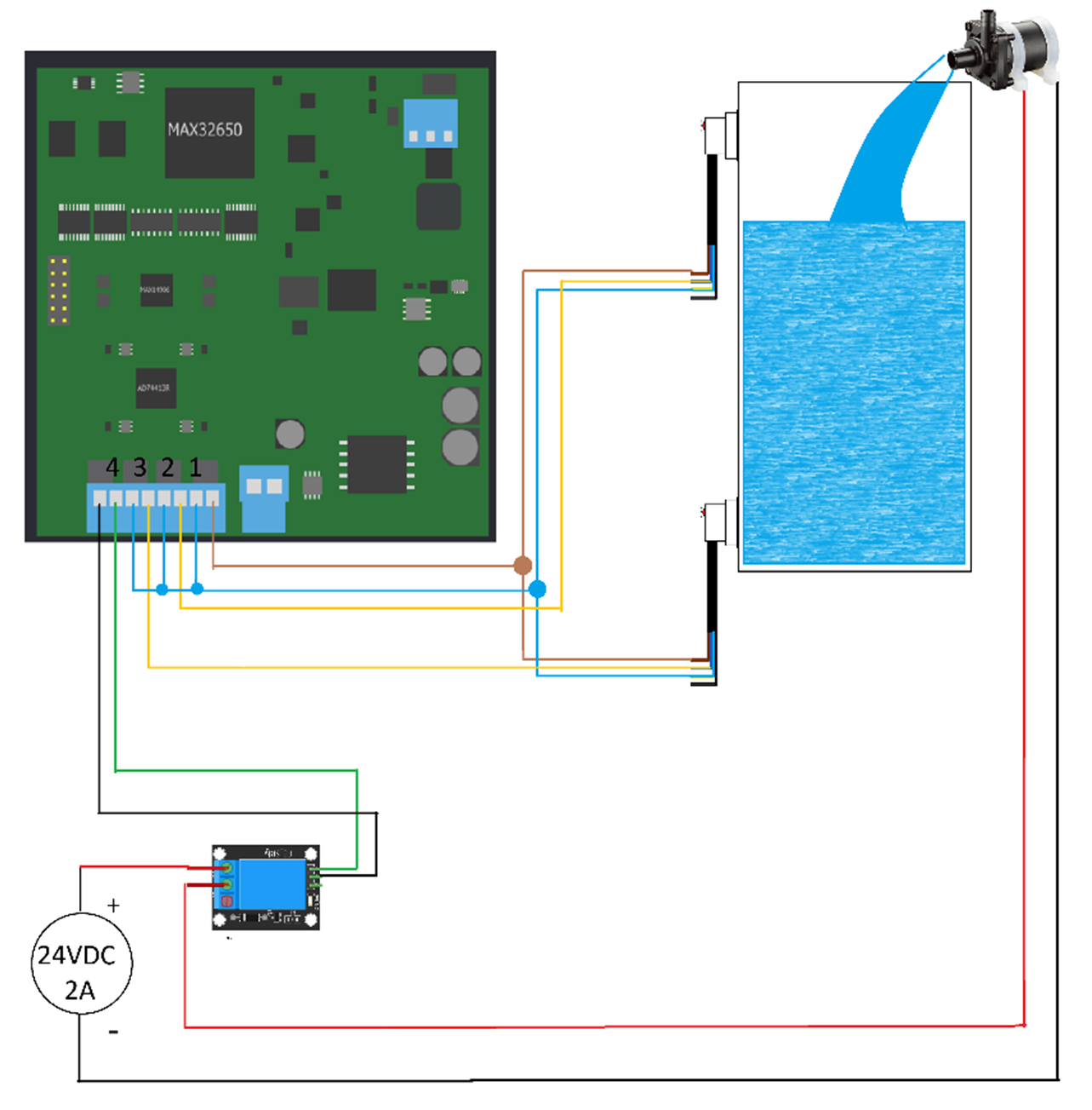
Figure 3: Wiring diagram for the project. (Source: Green Shoe Garage)
Connecting the Water Pump
The water pump requires an external 24VDC power source, so we will have to activate it using a relay control board. The pump will receive its command and control from a digital pin on the AD-SWIOT1L-SL development board. We will designate channel 4 of the AD74413R as the digital output and wire it to the control pin input of the relay control board.
Use the following procedure to wire the relay:
- Connect the channel 4 digital pin to the control input of the relay control board.
- Connect the GND pin of channel 4 to the GND pin of the relay control board.
- Connect the positive lead of the 24VDC power source to the NO terminal of the relay control board.
- Connect the positive lead of the water pump to the COM terminal of the relay control board.
- Connect the negative lead of the water pump to the negative lead of the 24VDC power source.
Software Development
This project will use Scopy and Microsoft Visual Studio Code, both of which are available for Windows, macOS, and Linux. However, in this article, we will use Windows.
To create the JavaScript file for the project, you can use a plain text editor or Visual Studio Code.
Note: As of the writing of this article, the primary version of Scopy is not compatible with the AD-SWIOT1L-SL development kit. Instead, you will need to download the Scopy AD-SWIOT1L-SL plugin.
Scopy Setup
Once you have downloaded and installed Scopy, launch the application.
Since the AD-SWIOT1L-SL development board does not have onboard USB, you will need to connect it to the host computer via the 10BASE-T1L-to-USB adapter board. Connect the adapter board and the AD-SWIOT1L-SL development board with the included orange cable (Figure 4). Next, connect the adapter board to the host computer via a micro-USB cable.
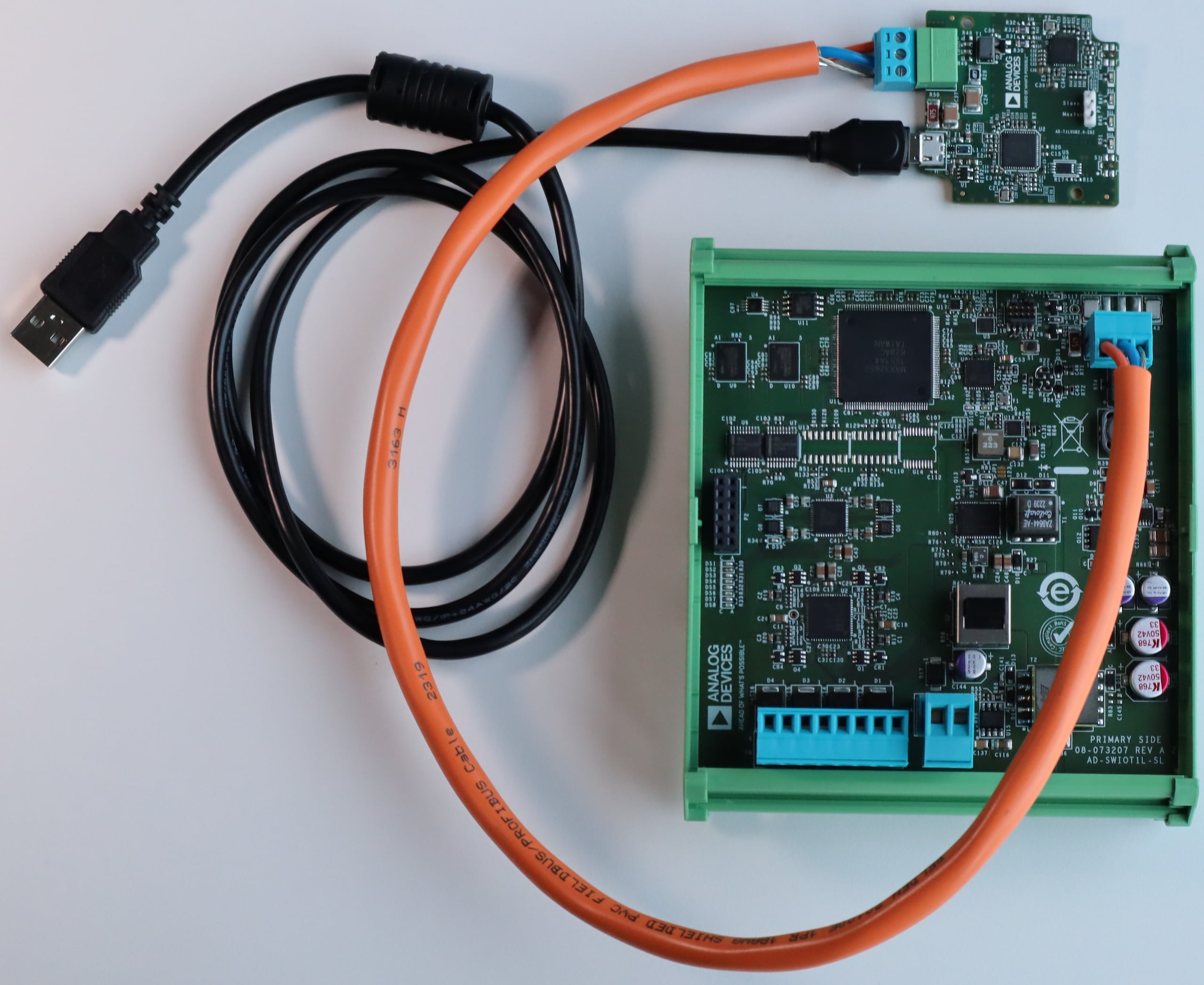
Figure 4: Use the adapter board to connect the AD-SWIOT1L-SL to the host computer for programming. (Source: Analog Devices)
If the application does not automatically detect AD-SWIOT1L-SL, enter the IP address 169.254.97.40 in the URI field and then click Verify (Figure 5). If the board is successfully detected, it will be listed at the top of the application. Then click Connect to launch the setup window (Figure 6).
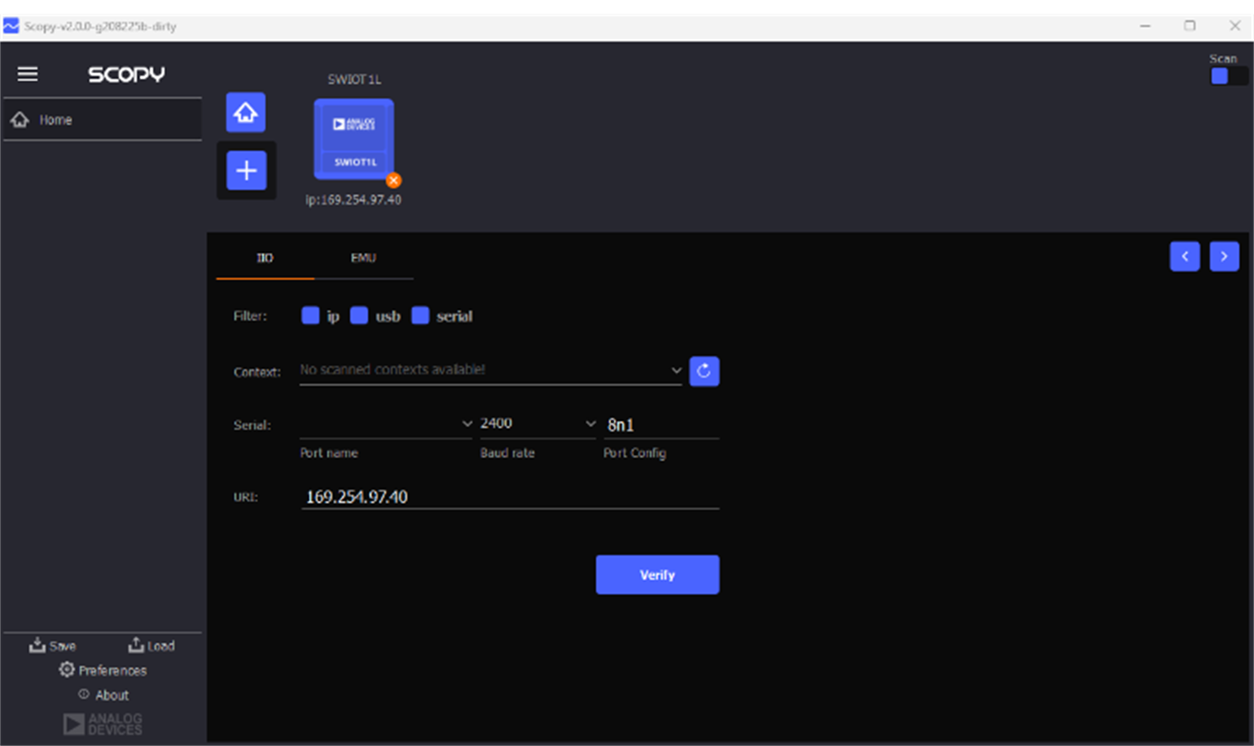
Figure 5: If the application does not automatically detect AD-SWIOT1L-SL, enter the IP address 169.254.97.40 in the URI field and then click Verify. (Source: Green Shoe Garage)
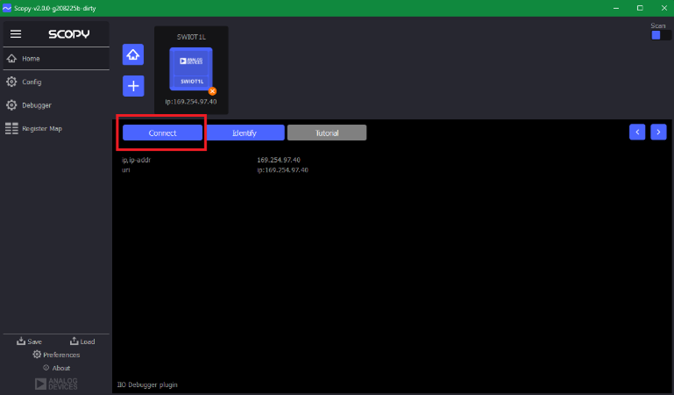
Figure 6: Adding the AD-SWIOT1L-SL development board and configuring the functionality in Scopy is simple. (Source: Green Shoe Garage)
Key Functions and Variables
The section describes several important functions and variables and provides custom code that we will load into Scopy.
launcher.reset()
This function initializes the hardware and prepares the AD-SWIOT1L-SL to run the script.
dio.running
This variable enables or disables the I/O channels as follows:
- Setting the variable to TRUE means I/O is ENABLED.
- Setting the variable to FALSE means I/O is DISABLED.
dio.dir[X]
Setting the variable to TRUE sets the I/O channel as an OUTPUT.
Setting the variable to FALSE sets the I/O channel as an INPUT.
dio.out[X]
Setting the variable to TRUE sets the I/O channel output as HIGH.
Setting the variable to FALSE sets the I/O channel output as LOW.
osc.channels[X].enabled
Setting the variable to TRUE sets the oscilloscope channel output as HIGH.
Setting the variable to FALSE sets the oscilloscope channel output as LOW.
osc.channels[0].volts_per_div = 1
A variable that sets the vertical axis of the oscilloscope, measured in volts per division.
var ppX = osc.channels[0].peak_to_peak
The function peak_to_peak() captures the instantaneous peak-to-peak voltage of the channel being polled.
function check_tank()
This function contains the custom code needed to operate our water pump system. It checks the status of the upper and lower sensors and sends a control signal to the relay control board accordingly.
function check_tank(){
var lower_sensor_status = dio.out[1]
var upper_sensor_status = dio.out[2]
if (lower_sensor_status == 0) { // lower sensor detects NO water
dio.out[3] = true // Turn pump ON
}
if (upper_sensor_status == 1) { // upper sensor detects water
dio.out[3] = false // Turn pump OFF
}
msleep(1000)
dio.running = false
}
function set_oscilloscope()
This function initializes Scopy's software-defined oscilloscope. The subfunctions mimic the control one would expect to find on the interface of a physical oscilloscope.
function set_oscilloscope(){
/* Enable Oscilloscope Channel 1 */
osc.channels[0].enabled = true
osc.channels[1].enabled = true
osc.channels[2].enabled = true
osc.channels[3].enabled = true
/* Set Volts/Div to 1V/div */
osc.channels[0].volts_per_div = 1
osc.channels[1].volts_per_div = 1
osc.channels[2].volts_per_div = 1
osc.channels[3].volts_per_div = 1
/* Set Time Base to 1 ms */
osc.time_base = 0.001
/* Set Time Position to 0s */
osc.time_position = 0
/* Run Oscilloscope */
osc.running = true
}
function main()
This is the main loop that runs after system initialization. Additional subfunctions can be added here to expand the system's functionality.
function main(){
set_dio()
check_tank()
msleep(1000)
set_oscilloscope()
msleep(1000)
var pp1 = osc.channels[0].peak_to_peak
var pp2 = osc.channels[0].peak_to_peak
var pp3 = osc.channels[0].peak_to_peak
var pp4 = osc.channels[0].peak_to_peak
printToConsole(pp1)
printToConsole(pp2)
printToConsole(pp3)
printToConsole(pp4)
}
Firmware Upload, Final Assembly, and Troubleshooting
Now that you understand how the firmware is structured and how it functions, upload the script using Scopy's debugger tool.
To open the debugger in Scopy, you must first make sure it is visible in the Instrument Menu:
- Close the Scopy application.
- Navigate to C:\Users\<your_username>\AppData\Roaming\ADI.
- Open the Scopy ini file.
- Change the debugger property from the launcher group from false to true (Figure 7).
- Close the file and reopen Scopy.
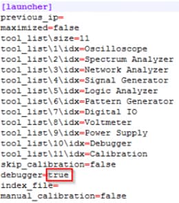
Figure 7: The debugging mode must be enabled by configuring a .ini file in the Scopy application install folder. (Source: Analog Devices)
Once you have restarted Scopy, load the script by following the instructions in the Scopy Scripting Guide (Figure 8).
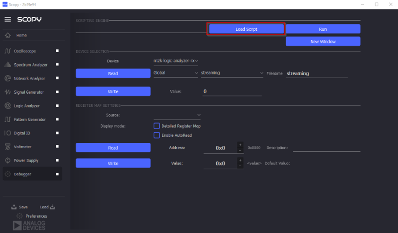
Figure 8: Scripts can be added to the dev board via the debugger menu. (Source: Analog Devices)
Assembly
- Affix the upper and lower sensors to the tank you wish to monitor and control. Ensure they are seated firmly and as flat as possible on the external tank surface.
- Connect the water source to the water pump.
- Connect a hose to the water pump outlet and place the open end into the tank.
- Ensure that the electronics and electrical supplies are at a safe distance from water sources and the tank.
Troubleshooting
If you find that you are having with your project, here are some troubleshooting tips that we discovered during development:
- Be sure that the relay control board is wired in a manner corresponding to the software. That is, depending on whether you are using the relay in a NO or NC manner, the software reflects that in the control output on channel 4 (Active High versus Active Low).
- Ensure the power supply can source the needed current for the pump to operate. Check the datasheet specifications of your pump and power supply to ensure compatibility.
- Use the Scopy signal scope functionality to see how the I/O channels are reacting to input changes.
- If the water level sensor is not triggered by the presence of liquid, remove power to the sensor, open the sensor enclosure, use a screwdriver to adjust the sensitivity, and reconnect power.
- Ensure all connections between the sensor and the AD-SWIOT1L-SL board are secure and correctly wired. Double-check the wiring diagram in Figure 2.
- Listen for a clicking sound when the mechanical relay switches. If you don't hear it, the relay might not be receiving the signal or may be bad.
- Ensure that all components (AD-SWIOT1L-SL board, relay board, pump, and power supplies) share a common ground to avoid ground loops and ensure proper operation.
- Temporarily connect the pump directly to the 24V power supply to ensure it operates correctly. This can help determine whether the pump or the relay control circuit is the issue.
In Summary
The Analog Devices AD-SWIOT1L-SL is a powerful development kit for prototyping intelligent and secure industrial devices that can connect to a network that supports 10Base T1L technology.
The included Scopy software allows users to interact with the hardware devices through a GUI, eliminating the need for complex programming. This makes it easier for people with no or limited coding experience to develop functional prototypes. The low-code nature of the Scopy scripting environment offers simple pre-written code blocks and visual tools to simplify development. This allows for more complex applications than no-code but still reduces the need for extensive coding expertise. The benefits of no-code/low-code development afforded by Analog Devices’ AD-SWIOT1L-SL and the Scopy tool include:
- Faster development times: By eliminating the need for extensive coding, applications can be built more quickly.
- Increased accessibility: These platforms empower non-technical users to create solutions without relying on professional programmers.
- Reduced costs: The need for fewer professional developers can potentially lower development costs.