Importance of 5G Low-Noise Amplifiers (LNAs) and Bandpass Filters (BPFs)

Image Source: Monster Ztudio//Shutterstock.com
By Steve Taranovich for Mouser Electronics
Published August 25, 2021
The 5G wireless communication standard has seen a steady increase in data transmission rates in recent times. The 5G New Radio (NR) standards will provide a solution for user demands in mobile broadband for new areas such as the Industrial Internet of Things (IIoT), autonomous driving, vehicle-to-everything (V2X), reliable remote healthcare, smart cities, and so much more. Low-noise amplifiers (LNAs) and bandpass filters play a crucial role in bringing this to life. Let’s review the roles they play.
Low-Noise Amplifiers
Low-noise amplifiers optimize signal sensitivity and improve the signal-to-noise ratio of mobile cellular systems in handhelds and base stations. LNAs can extend the area of the highest data traffic, distant from the next base station with maximum network efficiency by reducing transmission power in conjunction with the lowest bit-error rates.
LNAs enable higher download rates in media applications such as downloading photos from the cloud to a smartphone. These 5G LNAs also improve data connectivity to each handheld device. Low noise is a must because the LNA must process incoming weak signals from the receive antenna. The LNA will then amplify that tiny signal to usable 0.5V or 1V levels. A bandpass filter is placed after the LNA to pass the frequencies of interest in the particular band. The best bandpass filters are surface acoustic wave (SAW) designs with the steepest skirts to enable many adjacent frequency bands without interfering (Figure 1, lower curve).
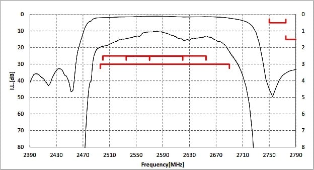
Figure 1: This shows the bandpass response of a SAW filter (lower curve) and the insertion loss (IL) upper curve (Image Source: Murata)
5G wireless systems use mm-wave frequencies to provide 100Mbps high-data rates to end users in metropolitan areas. The current limitation with 4G and LTE networks is the total usable fractional bandwidth (FBW), which is the bandwidth of a device divided by its center frequency. The same FBW at mm-wave frequencies provides much higher bandwidth, which gives the end-user higher data rates.
Millimeter-wave bands above 24GHz for 5G mobile communication enable a higher data rate. To meet the varying demands for 5G applications, a higher spectral efficiency, and higher network reliability, are also necessary. Therefore, a high-performing LNA is essential as the first component of a receiver front-end because it has a large impact on the lower boundary of the dynamic range.
Infineon has such LNAs to meet these needs, enabling wide frequency ranges for LTE and 5G. Its BGA9C1MN9, BGA9H1MN9, and BGA9V1MN9 LNAs have a very low bypass current of 2μA and a 1.2V operating voltage, which enables low-power consumption. The devices cover a wide frequency range from 4.4GHz to 5.0GHz.
In 5G applications, operating at or near mm-wave frequencies, semiconductor technologies are pushed to their limits in gain, noise figure, and linearity. This LNA provides up to 19.0dB gain and 1.0dB noise figure.
These devices also have gain step features to adjust their gain and linearity to increase dynamic system range and deal with changing interference occurrences. The in-band input third-order intercept point (IIP3) of the LNA is critical for operation in an environment where interferers are to be expected. This LNA meets this need with a very good IIP3.
This LNA also has a high electromagnetic interference (EMI) robustness (Figure 2).
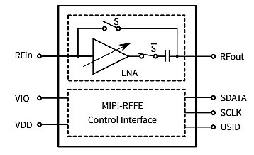
Figure 2: A block diagram of the Infineon LNA #BGA9C1MN9 (Source: Infineon)
This LNA contains an integrated MIPI RFFE interface operating in the 1.65V to 1.95V range. This is a control interface that simplifies the integration of complex RF front-end devices. This device has a software programmable MIPI RFFE USID with a USID select pin.
These MMICs contain gain-switching, biasing, and matching circuitry so that designers implement it simply into their RF design. These LNAs also exhibit best-in-class ultra-low noise factor (NF), high linearity, low-current consumption, pin-to-pin compatibility, and small package size of 1.1mm x 1.1mm. These properties are necessary in a 5G multiple-input and multiple-output (MIMO) receiver front-end for modern mobile devices such as a phone or a hotspot.
Bandpass Filters
5G filter needs are far more difficult than those for 4G, which only needed filters with around 60MHz to 70MHz of bandwidth at about 2GHz.
The requirement to use mm-waves for cellular/cordless phone communication leads to complex filtering challenges such as low in-band insertion loss and high out-of-band rejection—a difficult task for frequencies beyond 20GHz. Small-cell front-end modules (FEMs) will also deploy advanced filtering technologies to isolate the communication bands from nearby interferers.
Two frequency bands are supported by 5G New Radio (NR) devices: FR1 and FR2. FR1 spans the frequency range from 450MHz to 6000MHz; FR2 is from 24250MHz to 52600MHz. Filters designed for use in 5G NR devices are called 5G NR filters. The filters used should support below 6GHz and above 6GHz bands. We will be interested in the FR1 band in Band n41 (called TD2600+) here. This band spans 2496MHz to 2690MHz with a 194MHz bandwidth. Bands in this FR2 millimeter-wave range have a shorter range but higher available bandwidth than bands in the FR1 frequency band.
5G NR systems will need RF filters with high-percent bandwidths, excellent temperature stability, low-insertion loss, transmit power per range requirement, and good selectivity. Surface acoustic wave (SAW) filters are excellent in this role.
The use of SAW filters
SAW filters are compact and low-cost RF filters that can be used in a wide range of applications with frequencies as high as 3GHz. SAW filters operate by converting electrical energy into acoustic or mechanical energy on a piezoelectric material. The filter architecture uses interdigital transducers (IDTs).
The IDTs have interleaved metal electrodes on each end of the device that converts an electrical signal into an acoustic wave and then back to an electrical signal again (Figure 3).
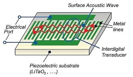
Figure 3: This image shows a typical SAW filter architecture (Source: EverythingRF.com)
When the electrical energy is converted into acoustic waves, those waves travel across the surface of an elastic, piezoelectric material that has an amplitude decaying into the substrate material, such as quartz, lithium tantalite (LiTaO3), or lithium niobate (LiNbO3). This decay is what causes insertion loss in SAW filters.
A major advantage of SAW filters is that they exhibit very sharp response characteristics and a low-insertion loss. This filter architecture is designed with relatively high-port impedances. This high impedance benefits designers of handheld wireless subscriber devices, with a low-power consumption for longer battery life.
Conclusion
Some of the 5G future goals that exist involve a unified and robust 5G air interface for next-generation wireless that can be seen in our time. 5G New Radio is the new radio access technology (RAT) that 3GPP has developed for the 5G (fifth generation) mobile network. It was designed to be the global standard for the air interface of 5G networks. The goal is to have diverse services such as enhanced mobile broadband, a huge Internet of Things (IoT), and mission-critical services. To make this a reality, a diverse spectrum of low bands (under 1GHz), mid-bands (1GHz to 6GHz), and high bands (above 24GHz) is available.
 Steve Taranovich is the author of the non-fiction "Guardians of the Right stuff", a true story of the Apollo program as told by NASA and Grumman Corp. engineers, an astronaut, and technicians. Steve was the Experienced Editor-In-Chief of EETimes/Planet Analog and Senior Technical Editor at EDN running the Analog and Power Management Design Centers from 2012 to 2019. He has a demonstrated history in electronic circuit design and applications for 40 years, and 9 years of technical writing and editing in industry. Skilled in Analog Electronics, Space-related Electronics, Audio, RF & Communications, Power Management, Electrical Engineering, and Integrated Circuits (IC). Steve Taranovich is a strong media and communications professional with a BEEE from NYU Engineering, 1972, and an MSEE from Polytech University in 1989. From 1972 to 1988, he worked as a circuit design engineer in audio (8 years) and microwave (8 years).