Lighting System Interconnection Levels
By TE Connectivity, edited by P. Golata
The lighting industry is now engaged in a metamorphosis similar to that experienced by the electronics industry in the 70s and 80s. At that time, to address this emerging market, AMP Incorporated developed the six Electronic Packaging Levels. These are now well grounded and used throughout TE Connectivity to categorize interconnects. This paper proposes a classification system that clearly defines natural demarcations that are inherent in all lighting systems.
Driven by the growing requirements of energy conservation, it was not until the 1990s when the efficient fluorescent bulb morphed into the now familiar compact fluorescent lamp (CFL) targeting residential/consumer use. Given the huge installed base of Edison sockets around the world, it was natural that the CFL was offered with an Edison base for easy, energy efficient, retrofit replacement. Even with the Edison base, the initial blue-white CFLs found poor consumer acceptance due to the harsh light and poor color rendition. Newer, higher quality warm-white products now on the market are finally gaining consumer recognition and are making their way into homes. It should be noted that as CFLs gain acceptance, certain states (California) now mandate that all energy efficient bulbs incorporate a new GU-24 bulb base rather than the Edison base thereby precluding installation into legacy fixtures. How this will develop and spread to other areas is being closely monitored. With that said, advocates of SSL readily point out the initial market failures of CFL and the need to provide a consumer-friendly lighting solution to prevent a similar initial market failure (“Compact Fluorescent Lighting in America: Lessons Learned on the Way to Market,” Pacific Northwest National Laboratory, June 2006, http://apps1.eere.energy.gov/buildings/publications/pdfs/ssl/cfl_lessons_learned_web.pdf).
We now find ourselves with a new solid state light source: the light emitting diode (LED). Although this phenomenon was first observed in the early 1900s, it was not until the turn of the current century that brought the development of InGaN and AlGaNP technology. This technology, along with advanced phosphor development, moved LEDs out of the realm of indicator lights and onto a growth path that offered the possibility of true “lighting class” LEDs. With the development and growth of LED technology, we see many similarities to the market path taken by earlier lighting technologies. The initial migration into retrofit applications and eventual transition into entirely new lighting designs is the most obvious similarity that comes to mind although more subtle technological similarities can be identified and will be shown later in this paper.
As these common segments began to solidify across the industry during the 1980s, AMP Incorporated naturally began to try to create order out of these segments so connector selection and identification was easier for our employees and customers. Richard Granitz first outlined the original Six Levels of Electronics Packaging (Granitz, R. F., “Levels of Packaging,” Instrumentation and Control Systems, August 1992).
Out of this effort rose the Eight Levels of Electronic Packaging that TE Connectivity personnel are now intimately familiar with and that is likewise commonly acknowledged in the electronic packaging world.
The Eight Levels of Lighting Interconnects
Lighting is no longer being thought of as an “electrical” product. The new technologies being rolled out and developed are resulting in the “electronification” of lighting. This lighting “electronification” offers a number of system parallels to the familiar electronic packaging seen in products ranging from cell phones to personal computers, albeit at a larger scale. Similarly, lighting designers are struggling with these new technologies and how to integrate them into new fixtures. Questions on which interconnect to use often confound the designer and are typically left until the last design step when a distributor catalog is picked up and something that “looks” like it will work is selected. Will the selected connector work? Perhaps, yes. Is it the optimum selection for the application? Probably not.
What a designer needs is a method that defines each level of lighting interconnects in a manner similar to what is done with electronic systems. When doing this, we can better isolate the specific connector applications and define the products and options available to the lighting designer. From an industry-wide standpoint, this will bring order to the design process and introduce connector consideration earlier in the design process where proper consideration and selection of the connector is best situated.
Proposed is a classification system that clearly defines natural demarcations inherent in all lighting systems regardless of the light source. While exceptions exist, eight levels of interconnects are easily identified in lighting systems and can be readily defined. What follows is a description and explanation of these levels. Identification of these levels thereby forms the basis for better identifying and communicating interconnect options available to all involved in lighting design and integration. As an added benefit, it provides a vehicle to identify product needs and gaps at each level that those in the connector industry are well posed to fill.
The intent of these levels is to provide differentiation between the different interconnect needs typically found in lighting applications. Detailed definitions of each of the proposed eight levels with lighting examples follow.
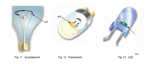
Level L1—Basic connection to the light emitting element. For an LED, this would be the wire bond to the die. For an incandescent bulb, it would be the weld to the tungsten filament.
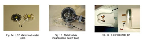
Level L2—Interconnection to the light source. In the case of an incandescent bulb, this would be an Edison base. For T5/8/12 fluorescents, it is the “tombstone.” For LEDs, this is typically a solder joint.
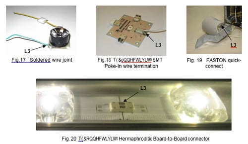
Level L3—Interconnection to the light source assembly. For an Edison base, this could be a crimp contact. For a fluorescent tombstone, this is typically either a poke-in or crimp termination. For LED assemblies on a printed circuit board (PCB), this could be a wire solder joint or a separable connection providing power into the assembly or to another assembly.
Level L4—Connection from an internal power supply to the light source assembly or device. For LEDs, fluorescent and metal halide systems, it is the power supply/driver/ballast output connection. This level is not required for primary direct-wired fixtures.
Level L5—Primary power interconnect from the primary installation wiring to the fixture.
Level L6—Fixture/installation primary power distribution. The installation is defined as the area where the light source is installed for use. This could be an automobile, building, office cubicle, room, or other similar area. An example of this would be a manufactured wiring power system used in an office environment to distribute primary power in an office cubicle. Another example is a manufactured wiring system used to connect and distribute power to lighting fixtures in a suspended ceiling.
Level L7—Premises line power feed to the installation power distribution (L6) or power source (L5). This is typically line voltage of 120VAC, 220VAC or, in some lighting applications, as high as 347VAC.
Level L8—Outside plant electrical power distribution system. It is similarly made of a number of systems with natural demarcations that could serve as the basis for a future paper on outside plant electrical levels but for the purposes at hand, we will refer to all outside plant levels as a single level L8.
|
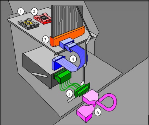
Figure 1: Comparison between lighting and electronic levels
From an interconnect standpoint, each level may have unique interconnect needs or, it may have a common need when compared to other adjacent levels. Certainly, if a common interconnect can be used in multiple levels, there are certain manufacturing and procurement benefits that can be realized, but this must always be balanced against technical and practical requirements for each level. There are, however, some generalities that can be drawn for connector types used at each level. Below we will investigate Levels L1–L6 since these are levels most closely related to lighting systems we’re commonly familiar with. Levels L7 and L8 will therefore be ignored for the most part.
At the most basic level, a Level L1 connection is the first connection that is made to a lighting element. As shown in a standard incandescent light bulb, this is a wire weld where the tungsten filament connects to support wires. In a fluorescent fixture, it is similarly a welded connection between the element and the electrode. Finally, in an LED, it is the wire bond between the die and a lead-frame.
Moving up a level to Level L2, this level is the first where a separable connector might be first implemented. The most common, recognizable termination at this level is the ubiquitous solder joint. As one might expect, the soldered LED termination to a PCB is a very common example found in SSL implementations. In traditional lighting, the socket used to connect to a lamp is an ideal example of an L2 termination. In incandescent implementations, the Edison-base screw base is the most recognizable. In fluorescent fixtures, the bi-pin “tombstone” connector readily identified in fluorescent fixtures is yet another example of an L2 termination. Of course, given the wide range of lamp styles available, there are an equal number of sockets too numerous to list that can also be similarly classified as L2 terminations.
At Level L3, wires are used that require some sort of connection method to provide power to an L2 socket or directly to the lighting device. In some instances, the wires can be soldered directly to the device and is indeed commonly done within the SSL assemblies. TE Connectivity has released the SMT Poke-In connector that provides a poke-in L3 termination to a printed circuit board thereby eliminating the need to solder the wire to the board. In other instances, it can also be the interconnection between circuit board assemblies as can be seen with the Hermaphroditic Board-to-Board connector used for SSL strip lighting. On the traditional lighting side, an L3 termination is typically just an FASTON, screw terminal, or poke-in terminal on the side or base of an Edison socket or fluorescent tombstone.
Continuing away from the lamp, we come to Level L5 which is the primary power connection to the fixture. This is a separable connector and is typified by a standard plug and receptacle configuration. In North America, this is the NEMA compliant two or three prong plug. In Europe and other locations, this is the DIN two pin plug. Since industry standard AC plugs are used, in most instances, this is a 120VAC/220VAC/277VAC/347VAC power source for most lighting applications. In some regions of the world, electrical codes allow recessed lighting fixtures to be pluggable using a TE Connectivity connector or equivalent as the primary power connection.
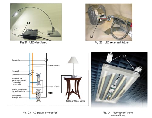
The last level to be discussed in this paper is Level L6. It is best characterized as the power distribution that takes place in the walls of a building. In almost all instances, this level is transparent to most end users but serves a vital role in distributing and providing power to the lighting fixtures. One such example of an L6 connection can be seen by simply removing the wall plate to an electrical outlet— the building wiring is either poked-in or screw terminated to the receptacle assembly. With ceiling or recessed lighting fixtures in North America, the L6 connection takes place in a junction box in the fixture. This box contains a screw terminal block or pigtailed wires from the fixture that are terminated to the building wiring with wire nuts or free-hanging poke-in terminations.
