Keeping a Virtual Eye on your Assets
Asset Tracking with the STMicroelectronics LoRa® IoT Tracker

Image Source: imajinajib/Shutterstock.com
By Greg Toth for Mouser Electronics
Published October 16, 2020
The STMicroelectronics LoRa® Internet of Things (IoT) tracker is an evaluation board that simplifies prototyping, development, and evaluation of IoT tracker applications, such as assets, people, and animal tracking and fleet management. In this project, we'll set up an asset-tracking prototype consisting of the STM LoRa IoT tracker, a LoRaWAN™ gateway and Loriot server, and the myDevices Cayenne portal displaying real-time tracker data.
Project Materials and Resources
The project bill of materials (BOM) lists components used in this project. Additional hardware and software development tools are also identified.
Project Bill of Materials (BOM)
- 511-STEVAL-STRKT01 - STMicroelectronics STEVAL-STRKT01 LoRa IoT tracker
- 511-P-NUCLEO-LRWAN2 - STMicroelectronics P-NUCLEO-LRWAN2 STM32 Nucleo Pack (for US915 and EU868 operation)
Hardware
- LAN network with a Dynamic Host Configuration Protocol (DHCP) server, internet connectivity, and without a firewall or proxy that blocks outgoing traffic to the Internet
- Personal computer (PC) running Microsoft Windows®, macOS, or Linux
- Two (2) USB Type-A to Micro-B cables
Accounts and Software
- Web browser for accessing software download sites and portals
- STMicroelectronics FP-ATR-LORA1 STM32Cube function pack for IoT tracker node with LoRa connectivity, GNSS, and sensors
- STMicroelectronics ST-LINK driver, if using a Windows-based PC
- Login account for myST for downloading STMicroelectronics software
- Login account for io to set up a LoRaWAN server
- Login account for myDevices Cayenne to set up a sensor data dashboard
- Serial terminal program such as Tera Term on the PC
Project Technology Overview
STMicroelectronics STEVAL-STRKT01 LoRa® IoT tracker
The STMicroelectronics LoRa IoT tracker (Figure 1) is a small battery-powered sensor and communications board for prototyping and evaluating asset-tracking applications. It communicates over LoRaWAN™ networks, which provide low-power, long-range wireless communications. The tracker contains an embedded LoRa module from Murata along with several sensors: a Teseo-LIV3F Global Navigation Satellite System (GNSS) for obtaining location information from global satellite positioning systems, a LIS2DW12 3-axis accelerometer for detecting motion and orientation, an HTS221 temperature and humidity sensor, and an LPS22HB barometric pressure sensor. The board has a built-in lithium polymer (LiPo) battery charger and a USB Type-C port for charging and serial communications. Push buttons control board operations, including on/off and sensor data transmission. Onboard EEPROM stores configuration parameters and can also be used to store logging data.
More detailed information about the LoRa IoT tracker can be found on Mouser and on STMicroelectronics.
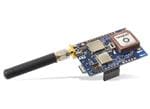
Figure 1: STMicroelectronics LoRa IoT tracker is a small battery-powered sensor and communications board for prototyping and evaluating asset-tracking applications. (Source: Mouser Electronics)
STMicroelectronics P-NUCLEO-LRWAN2 STM32 Nucleo Pack
The P-NUCLEO-LRWAN2 STM32 Nucleo Pack (Figure 2) provides two boards for prototyping LoRaWAN-based applications: An 8-channel LoRaWAN gateway board for connecting end-node devices to a backend LoRaWAN server running in the cloud, and an end-node board containing a collection of sensors and a LoRaWAN communications module. For this project, we'll only be using the gateway board, and you can use the end-node board for other projects.
LoRaWAN frequencies vary by country, and in the United States, it runs in the 902MHz to 928MHz range, which is referred to as US915. The P-NUCLEO-LRWAN2 Nucleo Pack is for LoRaWAN communications in the 868MHz and 915 MHz bands, and a separate P-NUCLEO-LRWAN3 is available for communications in bands below 500MHz.
The gateway board has a LoRaWAN antenna connector, an Ethernet jack for internet connectivity, user LEDs and pushbutton, and a built-in ST-LINK/V2-1 programming tool, which we'll use to program software onto the LoRa IoT tracker.
More detailed information about the P-NUCLEO-LRWAN2 can be found onMouser and at STMicroelectronics.
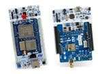
Figure 2: STMicroelectronics P-NUCLEO-LRWAN STM32 Nucleo Pack provides two boards for prototyping LoRaWAN-based applications. (Source: Mouser Electronics)
STMicroelectronics FP-ATR-LORA1 STM32Cube Function Pack
The STMicroelectronics FP-ATR-LORA1 STM32Cube Function Pack is an application software package for the LoRa IoT tracker. It contains functions for initializing the tracker hardware, reading position from the GNSS module, reading the motion and environmental sensors, power management and low-power modes, LoRaWAN communications, and optional data logging to electrically erasable programmable read-only memory (EEPROM). It also provides a serial command interface for issuing commands to configure the tracker and display status information. Source code is included, which allows you to modify it for your prototyping needs.
More detailed information about the FP-STR-LORA1 function pack can be found on STMicroelectronics' website.
Loriot
The LoRaWAN communications protocol uses a LoRaWAN server that is typically running in the cloud. End nodes communicate with the gateway, and the gateway communicates with the LoRaWAN server. Several LoRaWAN servers are available both commercially and as open source. For this project, we'll be using the Loriot service (Figure 3), which provides a free tier for prototype development. The free tier allows you to define one gateway and up to 10 end-node devices, along with up to two application integration connectors for sending your device data to other applications such as data display dashboards. Loriot has servers in EMEA, Asia/Pacific, and Americas regions, and we'll be using a server in New York for this project.
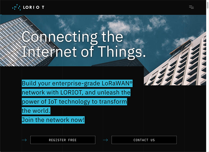
Figure 3: Loriot LoRaWAN Service provides a free tier for prototype development. (Source: Loriot)
myDevices Cayenne
myDevices Cayenne (Figure 4) is a cloud-based platform for building IoT applications involving sensors, widgets, dashboards, triggers, alerts, and application programming interfaces (APIs) to integrate with other systems and applications. It provides several pre-built integrations for various data formats, including the data format used by the STM LoRa IoT tracker.
We'll use Cayenne to display sensor and position data from our LoRa IoT tracker on a live dashboard that updates in real-time, including a real-time map of the tracker location. We'll be connecting Cayenne to our Loriot server through an application output connector.
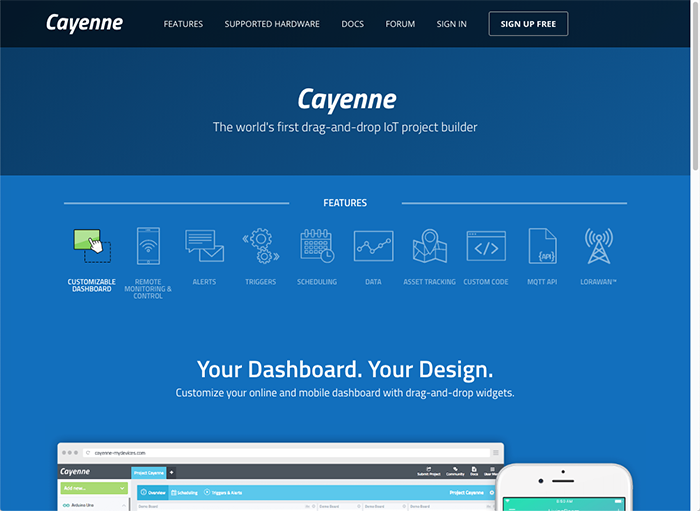
Figure 4: myDevices Cayenne is a cloud-based platform for building IoT applications. (Source: Cayenne)
The Setup (Hardware)
While setting up the hardware, be sure to remember that electronic components are static-sensitive, so handle accordingly.
Personal Computer (PC)
Power up the personal computer and allow it to boot up.
P-NUCLEO-LRWAN2 STM32 Nucleo Pack
Read through the P-NUCLEO-LRWAN2 sections of the User Manual to get familiar with the connectors on the NUCLEO-F746ZG and the Gateway Expansion Board. We won't be using the other NUCLEO-L073RZ board in this project.
Unbox the NUCLEO-F746ZG gateway board and connect one of the 868MHz to 915MHz antennas to the Gateway Expansion Board's antenna connector. Remove both jumpers in position CN4. This will direct the board's ST-LINK/V2-1 programmer interface to the CN6 connector that we'll use to program the LoRa IoT tracker.
Leave the Ethernet port disconnected for now and connect two USB Type-A to Micro-B cables to the CN1 USB Micro-B port on the base board and the CN1 USB Micro-B port on the gateway expansion board, but don't plug either of them into the PC yet.
If you're using a Windows-based PC, you'll also need to download and install the STM ST-LINK/V2-1 USB driver (free registration on myST.com is needed to download the software).
LoRa IoT tracker
Follow the LoRa IoT tracker User Manual to assemble the board, battery, antenna, and case. Use the 5-pin multi-colored cable to connect the LoRa IoT tracker's 5-pin programming connector to CN6 on the NUCLEO-F746ZG, being sure to observe the pin orientation (Figure 5) with pin 1 on NUCLEO CN6 connecting to pin 5 on LoRa IoT tracker CN501. A Pin 1 indicator is on the LoRa IoT tracker case, and pin 6 on the NUCLEO-F746ZG CN6 is not connected.
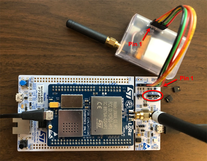
Figure 5: A 5-pin multi-colored cable connects the LoRa IoT tracker's 5-pin programming connector to CN6 on the NUCLEO-F746ZG. (Source: Mouser Electronics)
Connect the USB C cable to the LoRa IoT tracker and on the other end of the cable, attach the USB Type-A to USB C adapter. Plug the three USB cables into the PC in this order:
- LoRa IoT tracker
- Gateway expansion board CN1
- NUCLEO-F746ZG CN1
After connecting all three cables, a USB drive named NODE_F746ZG should appear on the PC. This is a drag-and-drop programming interface for the microcontroller on the LoRa IoT tracker, and we'll use it in the next section to program software onto the LoRa IoT tracker.
The Setup (Software)
LoRa IoT tracker and FP-ATR-LORA1
Web browse to the ST FP-ATR-LORA1 page and download the FP-STR-LORA1 software package. You'll need to register on myST.com to complete the download. On the Documentation tab, you'll find a User Manual and Quick Start Guide, which has additional information about setting up and using FP-ATR-LORA1. However, the examples use a different gateway and frequency band than what we're using in this project. For this project, we'll be setting up the tracker and gateway for operation on the US 915 MHz LoRa frequency band using channels 0 through 7.
Unzip the downloaded file and look for the file STM32CubeFunctionPack_LORA1_Vx.x.x/Projects/STEVAL-STRKT01/Applications/LoRa/Asset_Tracker/Binary/STEVAL_STRKT01_US915_HYBRID.bin
Drag that file onto the NODE_F746ZG USB drive to program that binary onto the LoRa IoT tracker. After programming has completed, the drive will disconnect and then reconnect.
Now unplug all three USB cables in this order:
- NUCLEO-F746ZG CN1
- Gateway expansion board CN1
- LoRa IoT tracker
Disconnect the 5-pin program cable and re-insert both jumpers in CN4 on the NUCLEO-F746GZ.
Now reconnect all three USB cables in this order:
- LoRa IoT tracker
- Gateway expansion board CN1
- NUCLEO-F746ZG CN1
Using the serial terminal program (Tera Term) opens both USB serial ports with settings 115200,N,8.1. One of the terminals will show the tracker serial console interface, and the other is the gateway serial console interface. These interfaces are used to configure the tracker and gateway settings as well as view informational messages.
Press Enter on the tracker console to confirm it's responding. Adjust your terminal CR/LF settings if necessary if the console doesn't respond to the Enter key. Type ?devicejoinparams followed by Enter and look for the DevEui(FromMcuId) value. This command displays the unique device EUI, which we'll need when setting up the device in Loriot.
Using the set of 16 hex digits shown for DevEui(FromMcuId) and without any spaces, issue the following command on the tracker console, substituting your DevEui(FromMcuId) hex digits in place of the xxs:
!deviceeui-xxxxxxxxxxxxxxxx
Next issue the following commands on the tracker console:
!joineui-0101010101010101
!appkey-01010101010101010101010101010101
!ntwkkey-0123456789ABCDEF0123456789ABCDEF
!sysreset
We'll come back to the tracker console later after getting things set up in Loriot.
Gateway Configuration
On the gateway console, type AT+MAC, followed by Enter. This command displays the gateway media access control (MAC) address that we'll need when setting up the gateway in Loriot. The Ethernet cable should still be disconnected from the gateway at this point.
Next, type the following commands on the gateway console to configure the gateway domain name system (DNS) servers, Network Time Protocol (NTP) server, channel plan, and Loriot server endpoint. You can adjust these as necessary for your particular environment, including using a different Loriot server than US2 (see Loriot setup section).
AT+DNS=8.8.8.8,8.8.4.4
AT+NTP=north-america.pool.ntp.org
AT+CH=US915
AT+PKTFWD=us2.loriot.io,1780,1780
After entering these commands, run the command AT+SYS and examine the configuration settings, similar to Figure 6. Note that the gateway Ethernet cable should still be disconnected.
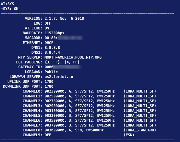
Figure 6: This is a rendering of gateway configuration settings (Source: Mouser Electronics)
Loriot
Web browse to https://loriot.io/ and sign up for a free account. During the signup process, you'll select a regional server to use, and here we're using US2, which corresponds to us2.loriot.io. The free account supports one gateway and up to 10 devices, which is fine for this project.
After setting up your account, log into the selected server, and you'll see the main dashboard. There should be no gateways defined and a SampleApp application already created for you, along with a Sample network already defined.
Configurate Gateway
In the Loriot portal, navigate to Networks → Sample network and then click Add Gateway. Browse through the base platforms list and click on STM P-NUCLEO-LRWAN 2 and 3. For the radio front-end, select P-NUCLEO-LRWAN all regions except CN470, and in the eth0 MAC address field, copy and paste the gateway MAC address found earlier on the gateway serial console. Scroll down and pick a location for the gateway and then towards the bottom of the page, click Register STM P-NUCLEO-LRWAN 2 and 3 gateway. A band plan of US915_CH0_7 will be automatically configured, and the gateway information page should resemble Figure 7.
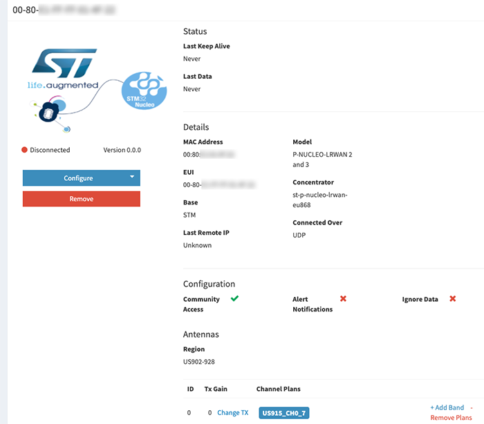
Figure 7: A band plan of US915_CH0_7 will be automatically configured, and the gateway information page will be shown. (Source: Mouser Electronics)
Connect Gateway Ethernet Cable
Connect the Ethernet cable to the gateway while watching the gateway console output. You should see messages indicating Ethernet started, DHCP IP address assigned, and uplink/downlink User Datagram Protocol (UDP) connected. The gateway status in Loriot (Dashboard → Networks → Sample network → Gateways) should now show Online.
Configure Device
Go back to the Dashboard and then navigate to Applications → SampleApp and click Enroll Device on the left side. Set the fields to the following values:
LoRaWAN Version: LoRaWAN 1.0.x
Enrollment Process: OTAA
Title: LoRa IoT Tracker
Device EUI: The 16 DevEui(FromMcuId) hex digits from the tracker console, without any spaces
Application EUI: 0101010101010101
Application Key: 0123456789ABCDEF0123456789ABCDEF
Leave the rest of the fields blank and then click Enroll. Afterward, the tracker should show up in the Devices list. Click on the device EUI in the devices list and then click LoRaWAN Parameters on the left side. Click Configure Parameters and set ADR (server-side) to Disabled, then click Accept.
Configure Application Integration
Return to the Dashboard and then navigate to Applications → SampleApp and look for the Application Outputs section. Click Manage outputs and then click Add new output. Look through the list of output types and select myDevices Cayenne, then click Add Output.
There are two Loriot values you'll need in the next step:
- Application ID–This is found by navigating to Applications → SampleApp and looking in the Details
- Access Token–This is found by navigating to Applications → SampleApp and clicking on Access Tokens on the left side, then looking in the Authentication Tokens Click the "view" icon next to the authentication token to display the entire token so you can copy and paste it while setting up myDevices Cayenne in the next step.
myDevices Cayenne
Web browse to myDevices Cayenne and sign up for a free account. After establishing your account, log back in, and you should see an initial setup page (Figure 8). Note that the Cayenne web UI changes its appearance and menu layouts depending on the browser window’s side, so you might need to adjust your browser window size to see everything.
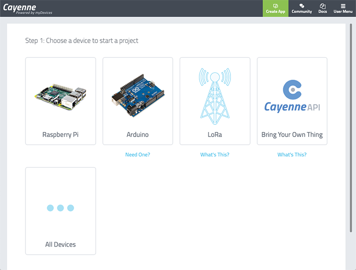
Figure 8: After establishing a myDevices Cayenne account, log back in, and you should see an initial setup page. (Source: Cayenne)
Click the LoRa icon and then under the Network column on the left, click on Loriot. Make sure you have the Loriot network selected before proceeding further. Scroll through the list of devices on the right side and click on STM32 B-L072Z-LRWAN1. Set the Name field to LoRa IoT Tracker, and in the DevEUI field, copy and paste the tracker's 16-digit DevEui(FromMcuId) hex string without any spaces. Leave the Activation Mode field set to Already Registered. Set the Loriot Server to us2.loriot.io or whatever Loriot server you picked when setting up your Loriot account. The Loriot App ID and Loriot Token values correspond to the Application ID and Authentication Token strings described during the Loriot setup steps. Copy and paste the 8-digit Loriot SampleApp Application ID into the Loriot App ID field in Cayenne and copy and paste the Loriot SampleApp Authentication Token into the Loriot Token field in Cayenne. Leave the Location field set to This device moves. Carefully check all your entries, then click Add device.
At this point, you should see an empty dashboard while Cayenne waits for tracker data to be received.
Run the Application
Both the tracker and the gateway have been running while the various components and servers were being configured. To get back to a fresh state, press the reset button on the gateway and then restart the tracker by either fully power cycling (disconnect the USB cable, hold the middle button down at least 7 seconds, then press the side button at least 2 seconds) or using the !sysreset tracker console command.
The tracker software runs on a timer schedule for reading sensors and transmitting data to the gateway. It also responds to being moved (based on accelerometer readings) or the tracker pushbutton being pressed. The sensor data transmissions are also influenced by whether the tracker has a GPS satellite fix, and the fix status is displayed on the tracker serial console output.
To check whether the tracker has successfully joined the LoRaWAN network, use the !devicejoinstatus command on the tracker console. If the device has successfully joined, the result will say, "LoRa has joined."
If you're initially running the tracker indoors without a clear view of the sky, leave it running for a while. Eventually, it will transmit sensor data that should be visible both in the Loriot device activity screen and in the Cayenne device dashboard (Figure 9). Since the tracker hasn't yet obtained a satellite fix, there won't be a location indicated on the map. Try heating or cooling the tracker or changing its orientation to see the temperature and/or accelerometer data change. You can also click the Data tab to view the sensor data in tabular format.
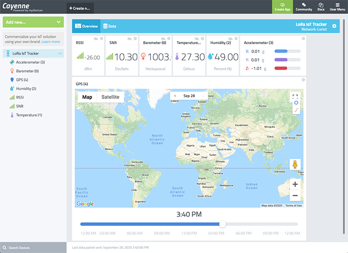
Figure 9: Cayenne dashboard without position fix. (Source: Cayenne)
Getting a Satellite Fix
Move the tracker outside so it can see GPS satellites. Eventually, it should acquire a position fix and start transmitting position data to Cayenne. Once that happens, the map display will show a tracker position on the map. You can use the blue circle and red line icons in the map’s upper right to toggle the tracker position history and track displays on or off. Figure 10 shows the Cayenne dashboard with the tracker running in a mobile environment (automobile driving around). Note that you'll need to be within range of Loriot-connected gateways for the tracker to work in a mobile scenario.
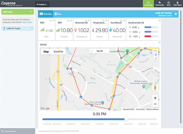
Figure 10: Cayenne dashboard with location measurements in a mobile environment. (Source: Cayenne)
At this point, your tracker is running continuously, periodically reading the sensors and transmitting sensor data to Cayenne through LoRaWAN wireless protocol, the gateway, Loriot, and Cayenne. Figure 11 shows the completed project with the tracker sitting indoors near the gateway board.
When the tracker is disconnected from the USB cable and running on battery power, you can power down the tracker by pressing and holding the SW500 user button (middle of the case) for around 7 seconds. To turn the tracker back on, either press the SW400 button (small hole in the side of the case) for at least 1.25 seconds or plug in the USB cable.
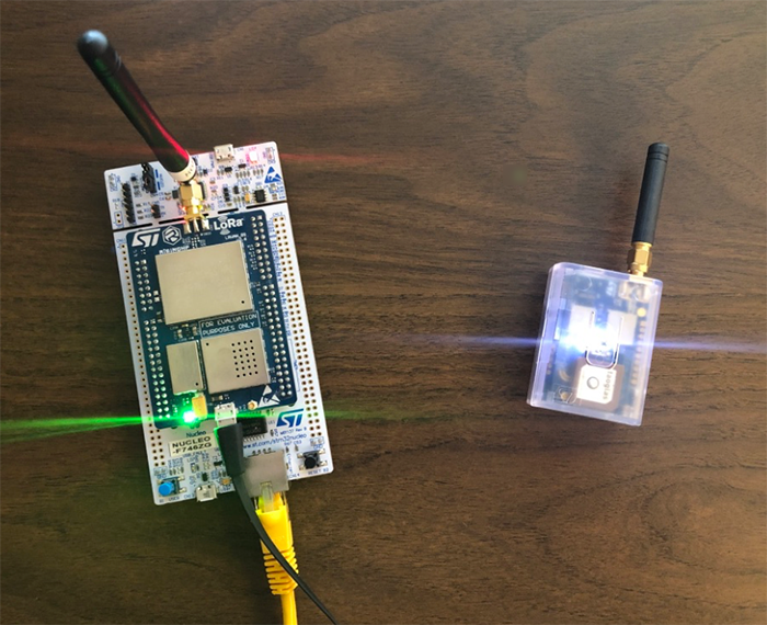
Figure 11: The completed project with the tracker sitting indoors near the gateway board. (Source: Mouser Electronics)
Troubleshooting Tips
- There are many parameters that have to be set correctly on the tracker console, the gateway console, in Loriot, and in Cayenne. Check all your settings carefully.
- Monitor the messages printed on the tracker console and gateway console to see what they're doing. In particular, check the network join status.
- Monitor gateway and tracker device stats in Loriot.
- Monitor device data transmissions in Cayenne.
- Don't place the tracker too close to the gateway; otherwise, RF transmission issues might occur.
- Make sure the tracker has a clear view of the sky; otherwise, it won't acquire a GPS signal.
- Read through the documentation for the tracker, FP-STR-LORA1 software, Loriot, and Cayenne for additional information and troubleshooting tips.
Conclusion and Where to Go Next
This project created an asset tracking application that sends real-time sensor data to myDevices Cayenne through LoRaWAN and the internet. It can be modified and extended in several ways, and here are a few examples:
- Examine and/or modify the LoRa IoT tracker application source code.
- Experiment with the geofencing capabilities of the tracker.
- Explore other application integration capabilities of Loriot.
- Interface the tracker with other LoRaWAN servers and/or other data display dashboards.
- Use the tracker with a different type of LoRaWAN gateway.
- Utilize the end-node board included in the P-NUCLEO-LRWAN2 STM32 Nucleo Pack.