Securing Your Assets with NXP’s MCX W71 Wireless MCU
Smart Meters & Home Security Solutions
By Joseph Downing, Mouser Electronics
Published February 5, 2025
Imagine having the ability to instantly detect and receive a warning about any tampering, theft, or abuse of your valuable assets, whether at home or in the workplace. This hands-on guide will show you how to configure NXP Semiconductors’ FXLS8974CF accelerometer and the NXP NMH1000 magnetic switch sensor using the Mikroe Hall Switch 3 Click board™ connected to the NXP FRDM-MCXW71 development board. These sensors can autonomously detect suspicious activity using low-power motion or magnetic wake-up features and transmit an alert message via Bluetooth® Low Energy wireless UART.
The core idea is to leverage advanced sensor technology to protect high-value or secure assets. For example, smart meters can monitor for tampering, enhancing home security by detecting unauthorized access to safes or lockers. Personal medical devices can be safeguarded against misuse, and laptops or tablets can be protected from theft. In industrial settings, warehouse theft detection and machine tampering alerts can significantly reduce losses and improve security. This technology can benefit even simple applications like door open/close detection.
The FXLS8974CF accelerometer and NMH1000 magnetic switch sensor are configured to detect specific motion or magnetic changes, respectively. When these sensors detect an anomaly, they trigger a low-power wake-up feature. This means the device remains in a low-energy state until it senses something unusual, conserving battery life. Once activated, the sensor sends an alert message via Bluetooth Low Energy, notifying the user immediately.
Project Materials and Resources
Project Bill of Materials (BOM)
Project Code/Software
Additional Resources
- Terminal software (such as PuTTY or the command line interface in the MCUXpresso IDE)
Additional Hardware
- PC running Windows
- USB Type-C to USB Type-A or Type-C cable (depending on PC USB port availability)
- TE Connectivity 535541-6 Pin Headers
Accounts
- NXP account (free to create)
Project Technology Overview
The NXP FRDM-MCXW71 development board (Figure 1) is a versatile and scalable platform designed for rapid prototyping and easy evaluation of the MCX W71 wireless microcontroller. This compact board is ideal for electrical engineers looking to explore the capabilities of multiprotocol wireless support, including Bluetooth Low Energy, Zigbee®, Thread, and Matter.
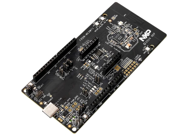
Figure 1: NXP FRDM-MCXW71 development board. (Source: Mouser Electronics)
Key Features:
- Onboard MCU-Link debugger simplifies debugging and programming.
- Industry-standard headers provide easy access to the MCU’s I/Os.
- External SPI flash memory enhances storage capabilities.
Ideal for developing IoT applications, smart home devices, and industrial automation systems, the FRDM-MCXW71 board offers a robust foundation for innovative projects.
The FRDM-MCXW71 board comes equipped with the NXP FXLS8974CF digital IoT accelerometer. This compact three-axis MEMS accelerometer is designed for a wide range of industrial and medical IoT applications that require ultra-low-power wake-up on motion functionality.
The Mikroe Hall Switch 3 Click (Figure 2) is a compact, magnetic field-activated switch designed to simplify your electronic projects. This add-on board, featuring the NXP NMH1000 Hall effect magnetic switch, is perfect for applications like electronic system wake-up, home automation (e.g., door/window open/close detection), contactless switches, and proximity detection.
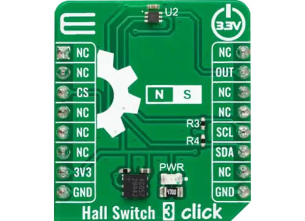
Figure 2: Mikroe Hall Switch 3 Click board. (Source: Mouser Electronics)
Key Features:
- mikroBUS™ compatibility enables easy integration with any host system supporting the mikroBUS standard.
- ClickID™ automatically detects and identifies the add-on board, simplifying setup and configuration.
- Open-source mikroSDK libraries enable flexible evaluation and customization.
Software Overview
MCUXpresso IDE
The MCUXpresso integrated development environment (IDE) (Figure 3) provides a user-friendly Eclipse-based development environment tailored for NXP MCUs using Arm® Cortex®-M cores, including both general-purpose crossover and wireless-enabled MCUs. This IDE delivers advanced editing, compiling, and debugging features, incorporating MCU-specific debugging views, code trace and profiling, multicore debugging, and integrated configuration tools.
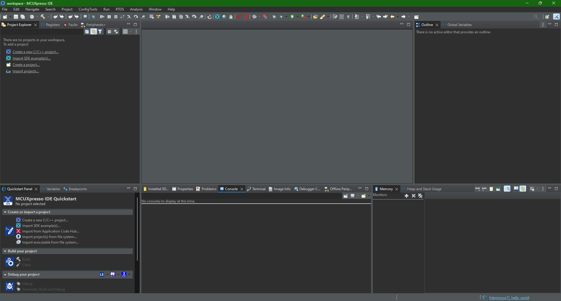
Figure 3: Main screen of the NXP MCUXpresso IDE. (Source: Mouser Electronics)
MCUXpresso SDK
The MCUXpresso SDK Builder (Figure 4) accelerates software development by providing open-source drivers, middleware, and reference example applications. The SDK Builder allows users to tailor and download a software development kit (SDK) that aligns with a chosen processor or evaluation board to streamline the development process. We will build and install the SDK in a later section.
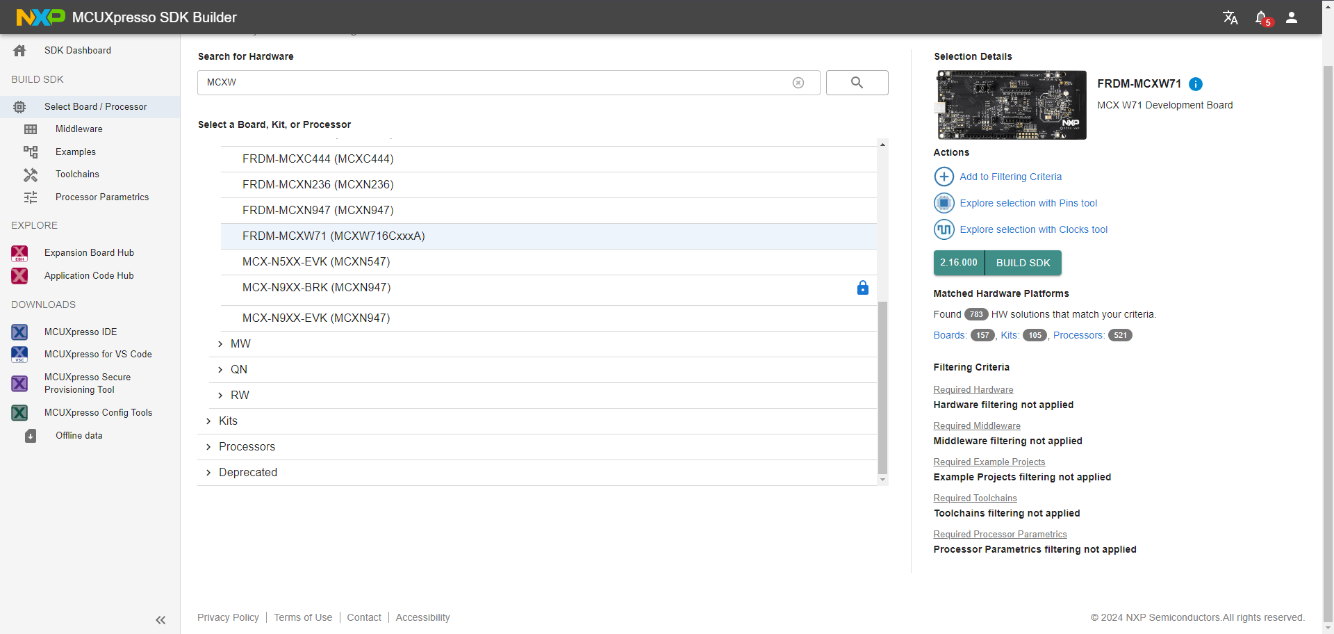
Figure 4: NXP MCUXpresso SDK Builder. (Source: Mouser Electronics)
NXP IoT Toolbox
The NXP IoT Toolbox (Figure 5) enhances the out-of-the-box experience by providing a user-friendly way to evaluate Bluetooth Low Energy, Zigbee, and Thread applications for NXP Connectivity chipsets. This all-in-one app, available on Google Play and the App Store, demonstrates NXP’s capabilities through Bluetooth Low Energy and custom proprietary profiles, enabling interaction with various smartphones.
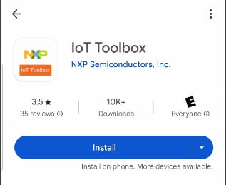
Figure 5: NXP IoT Toolbox for Android. (Source: Mouser Electronics)
Developing the Project
This project will show how to integrate different devices to develop a proof-of-concept that demonstrates this application.
Hardware Assembly
This project requires minimal hardware assembly.
- Connect the Hall Switch 3 Click board to the designated headers, paying attention to the correct position (Figure 6).
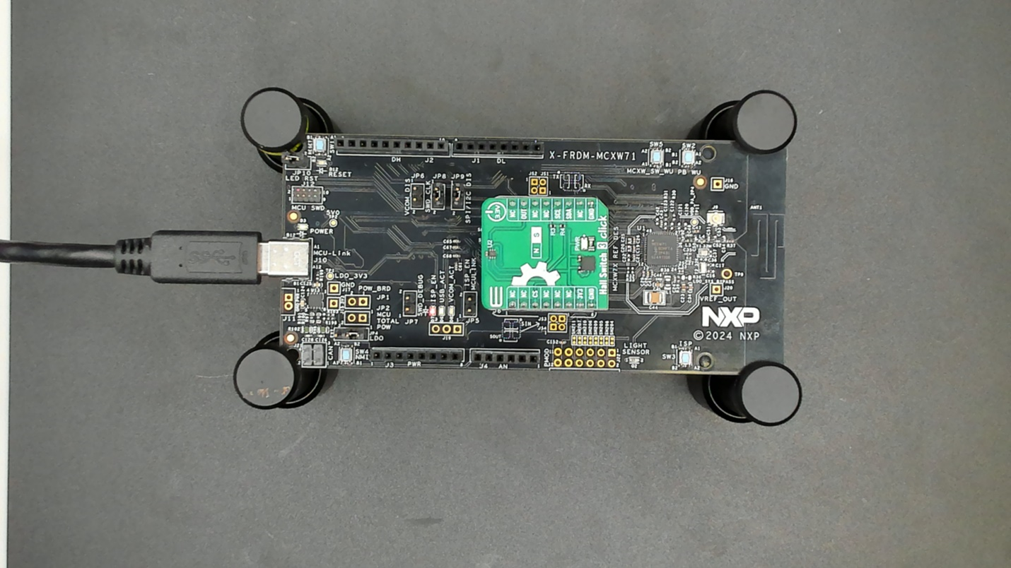
Figure 6: The Mikroe Hall Effect 3 Click board attached to the NXP FRDM-MCXW71 board. (Source: Mouser Electronics)
Software Installation
Installation is straightforward and requires navigating to NXP’s MCUXpresso IDE download site (Figure 7).
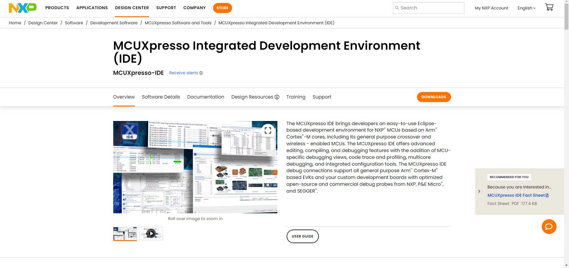
Figure 7: MCUXpresso IDE download page. (Source: Mouser Electronics)
- On the site, click the Downloads
- Navigate to MCUXpresso Integrated Development Environment (IDE)and click Download (Figure 8).
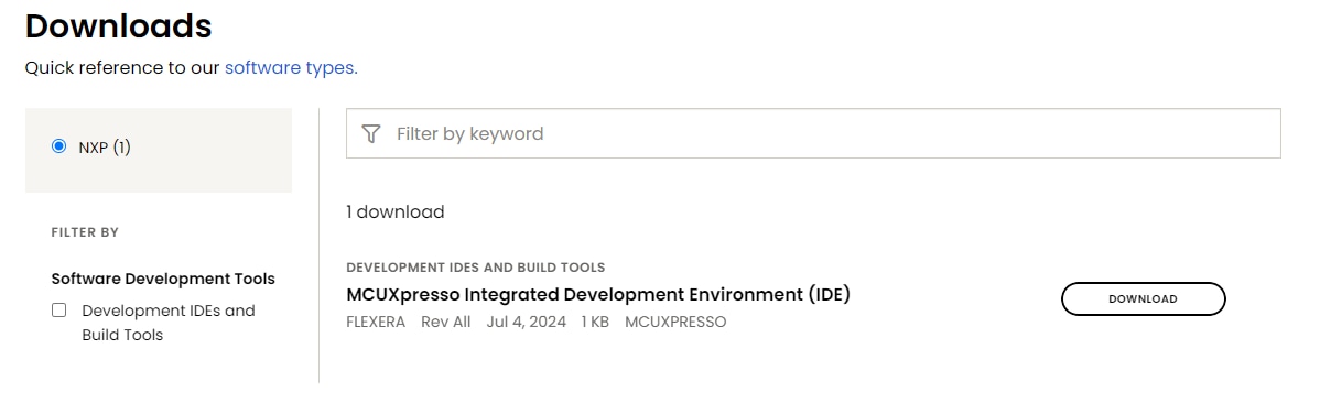
Figure 8: MCUXpresso IDE download tools. (Source: Mouser Electronics)
If prompted, follow the on-screen instructions to create an account. On the subsequent screens, you can choose which version you wish to download and which operating system (OS) you will use (Figure 9). This project uses MCUXpresso version 11.10.0 (you should download the most recent version) and Windows OS.
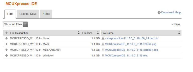
Figure 9: MCUXpresso IDE version and OS selection screen. (Source: Mouser Electronics)
SDK Installation
The SDK contains drivers, middleware, documents, examples, and other components. You can install the SDK from the previously provided link or the MCUXpresso IDE.
- Open the MCUXpresso IDE.
- On the welcome screen, click the Download and Install SDKs link (Figure 10).
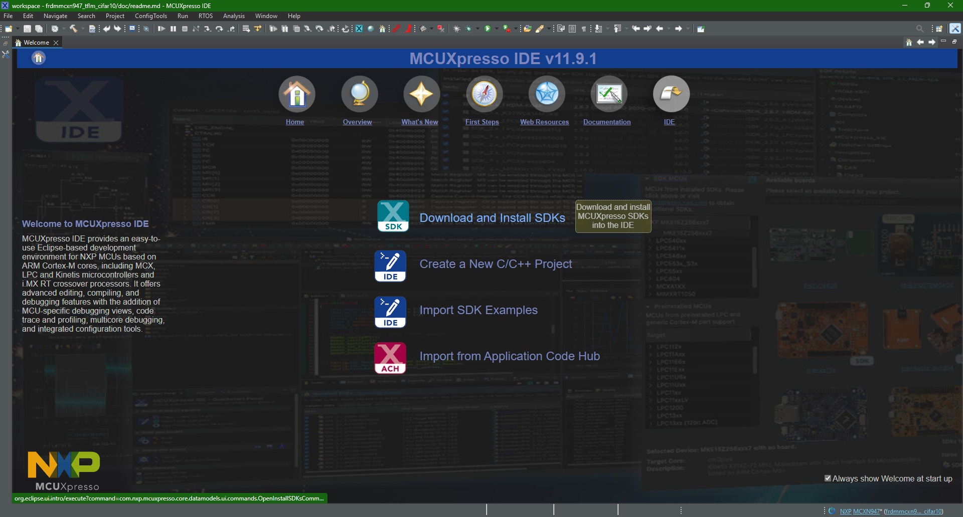
Figure 10: MCUXpresso IDE welcome screen. (Source: Mouser Electronics)
- In the Filter field on the right side of the screen, type “MCXW.”
- Select frdmmcxw71.
- Click Install (Figure 11) and wait until installation is complete.
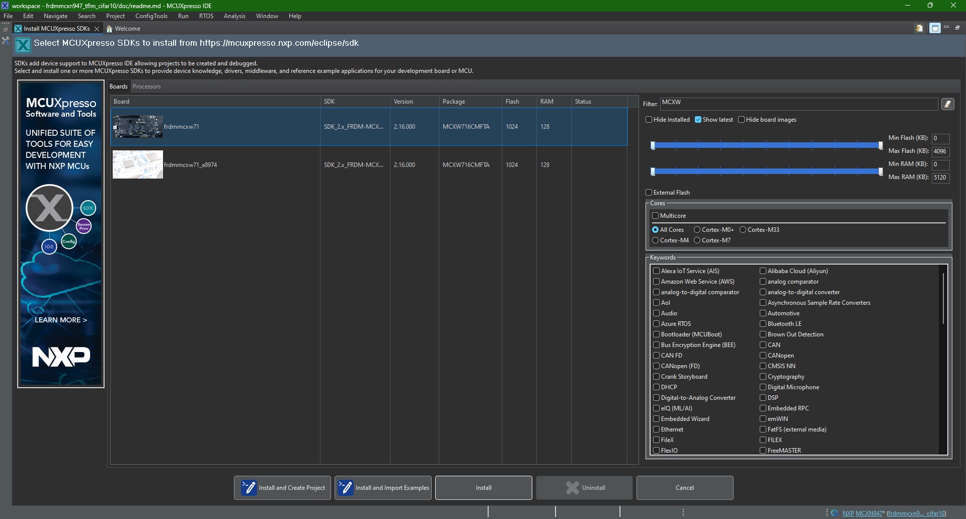
Figure 11: SDK installation board selection. (Source: Mouser Electronics)
Installing SPSDK and Uploading the NBU firmware
The Secure Provisioning SDK (SPSDK) is a versatile and dependable Python SDK library designed for seamless integration across the NXP MCU portfolio. This library enables users to connect and interact with devices, configure settings, and manage data operations, including secure data handling. The Narrow Band Unit (NBU) is a radio core that includes a Bluetooth Low Energy unit and dedicated flash. To ensure the proper device functionality for this project, we will need to update the NBU firmware.
Before updating the NBU firmware, download the example project.
- On the MCUXpresso IDE welcome page, click the Import from Application Code Hub link (Figure 12).
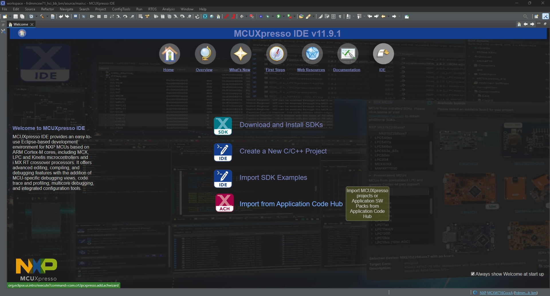
Figure 12: The Import Application Code link on the MCUXpresso IDE welcome page. (Source: Mouser Electronics)
- In the search window, type “Tamper detection + FRDM-MCXW.”
- Select the Tamper detection with low-power wake-up sensor using BLE wireless UART demo (Figure 13).
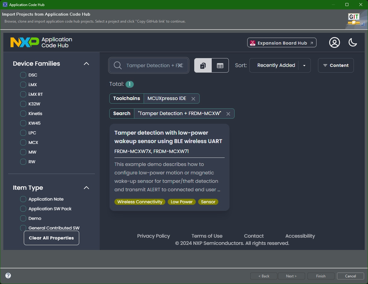
Figure 13: MCUXpresso IDE import project window. (Source: Mouser Electronics)
- At the top of the window, click GitHub Link.
- Once the link has finished loading, click Next.
- Select main as the git branch and click Next (Figure 14).
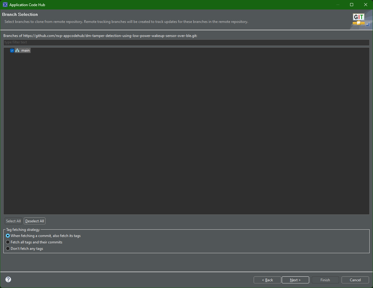
Figure 14: Application Code Hub branch selection. (Source: Mouser Electronics)
- In the next window, select the local destination directory and click Next.
- Leave the default wizard selected and click Next.
- Select both tamper_detect projects, and then click Finish (Figure 15).
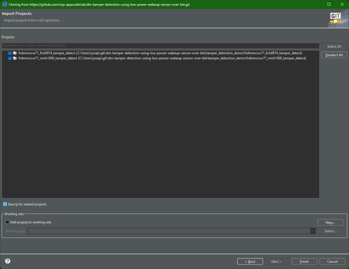
Figure 15: Project import and cloning from git. (Source: Mouser Electronics)
With the example for this project cloned, the location for the NBU file will depend on the destination folder you selected. From there, the NBU file will be in the following directory:
\git\dm-tamper-detection-using-low-power-wakeup-sensor-over
ble\tamper_detection_demo\frdmmcxw71_fxls8974_tamper_detect\nbu
To install the NBU firmware update, we first need to install the SPSDK.
- In Windows, open a command prompt window.
- In the command prompt, type the following (Figure 16).
python -m venv GetSpsdk
cd GetSpsdk
cd Scripts
activate
pip install -U spsdk
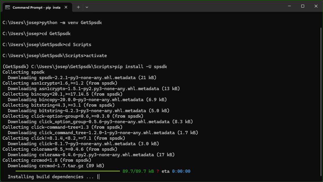
Figure 16: CMD prompt install for SPSDK. (Source: Mouser Electronics)
You can upload the NBU firmware from here.
Note: Copying the NBU file from its original location to a different directory may be easier.
- From the same command prompt, change directories to the NBU firmware location.
- While pressing SW3 on the FRDM-MCXW71, connect the board's J10 USB Type-C™ connector to the PC.
- Release SW3
- Using Device Manager, verify the location of the MCU-Link COM (Figure 17).
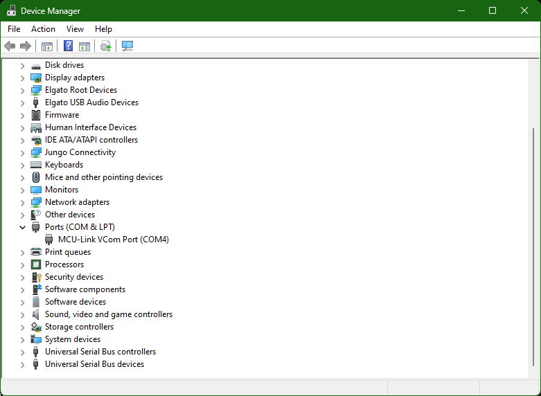
Figure 17: Device Manager window. (Source: Mouser Electronics)
- In the command prompt, type - blhost -p COMX -- receive-sb-file mcxw71_nbu_ble_1_9_14_0.sb3, replacing the X in COMX with the appropriate COM port (Figure 18).
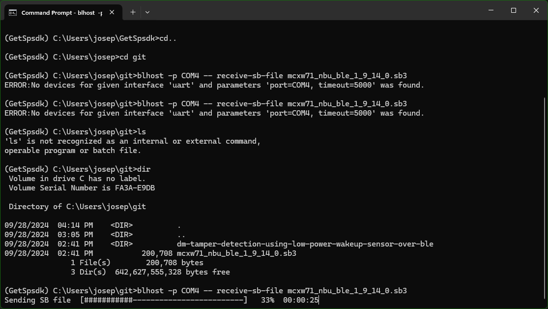
Figure 18: NBU firmware update. (Source: Mouser Electronics)
Execution
Now that the NBU firmware is updated and the example software has been cloned from the git repository, we can build and run the demonstration.
Software Integration and Demonstration
Open the MCUXpresso IDE. The example projects should appear in the Project Explorer window.
- Compile/build the frdmmcxw71_fxls8974_tamper_detect project by selecting the project from the project window and either clicking the Build icon or right-clicking the project and selecting Build (Figure 19).
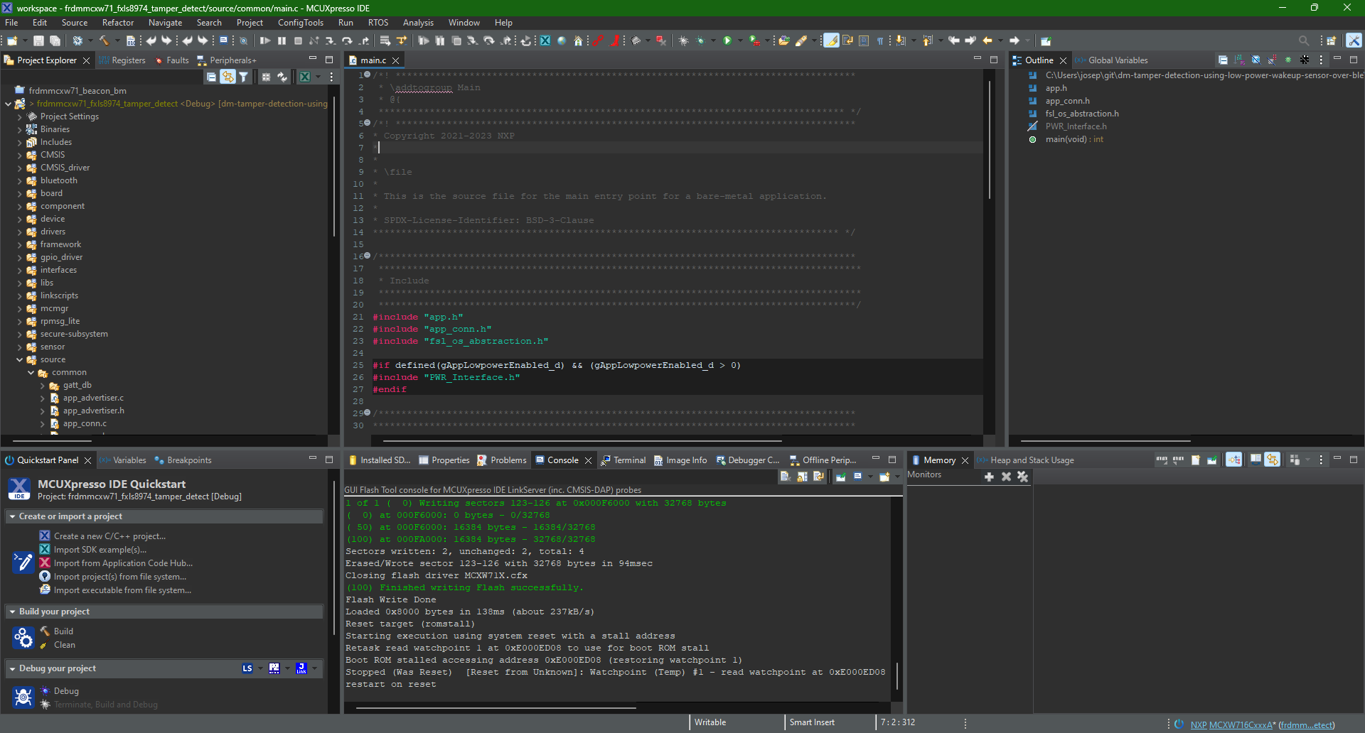
Figure 19: Built demo project inside MCUXpresso IDE. (Source: Mouser Electronics)
- Click the GUI Flash Tool icon.
- On the Probes discovered window (Figure 20), select MCU-LINK, and then click OK.
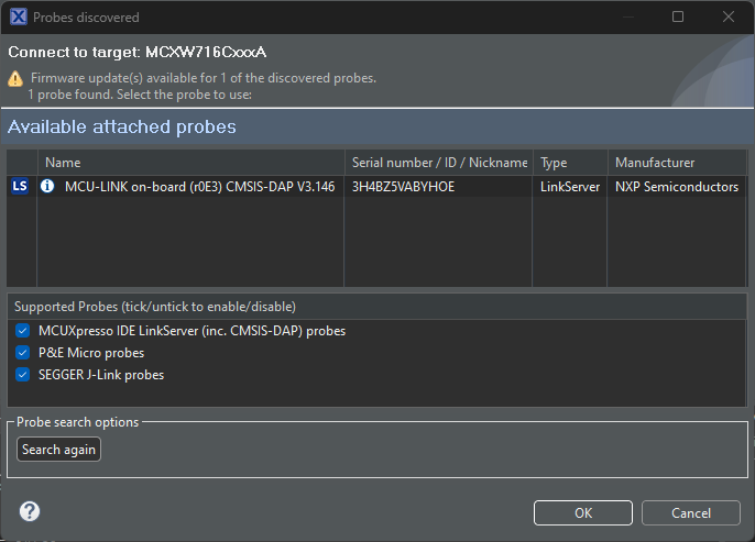
Figure 20: Probe discovery window. (Source: Mouser Electronics)
- In the next window, click Run… to begin programming. If the programming is successful, a blue LED will blink on the MCXW71 beneath the Click board.
- Open the terminal software, configure the COM port for the MCU, and set the baud rate for 115200 (Figure 21).
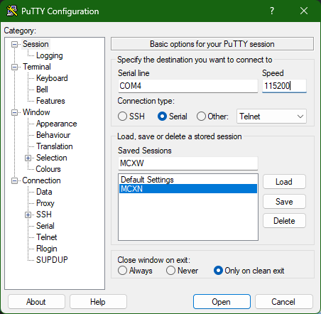
Figure 21: Terminal interface settings. (Source: Mouser Electronics)
- On your mobile device, open the NXP IoT Toolbox (Figure 22).
- Select the Wireless UART (Figure 23).
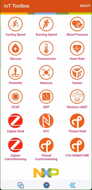
Figure 22: NXP IoT Toolbox. (Source: Mouser Electronics)
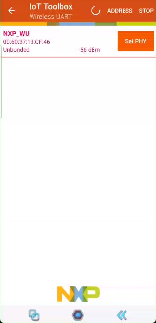
Figure 23: NXP IoT Toolbox Wireless UART screen. (Source: Mouser Electronics)
- Select the NXP_WU field.
- Move or shake the FRDM-MCXW71 board to activate the alarm. The following messages should appear in both the NXP IoT Toolbox (Figure 24) and the terminal window (Figure 25).
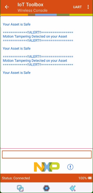
Figure 24: NXP IoT Toolbox wireless console motion tampering detection. (Source: Mouser Electronics)
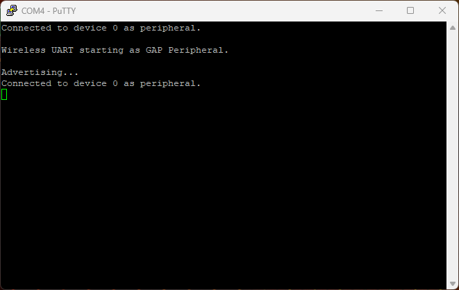
Figure 25: Terminal interface of the connected device. (Source: Mouser Electronics)
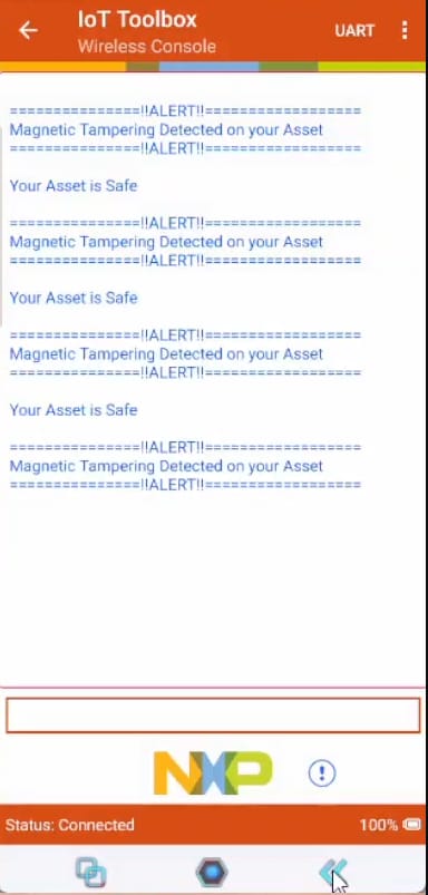
Figure 26: NXP IoT Toolbox wireless console magnetic tampering detection. (Source: Mouser Electronics)
- To test the Hall effect sensor, complete the programming steps above using the frdmmcxw71_nmh1000_tamper_detect Placing a magnet above the Click board will output the same results as shown in Figure 26.
Conclusion
The technology in this project is not just for tech enthusiasts; it has practical applications that can make everyday life safer and more secure. Whether you are protecting personal belongings, ensuring the integrity of medical devices, or securing industrial equipment, these sensors provide a reliable and efficient solution. Integrating these sensors into your security systems lets you stay informed and act swiftly, ensuring peace of mind in various environments.