As Robotics Goes All-Electric, Vendors Respond with Motion-Control Reference Designs
By Bill Schweber for Mouser Electronics
Featured Products
Featured Manufacturers
Related Resources
With the shift from hydraulic to all-electric robotic actuators, electronic-component vendors can now offer comprehensive motor control reference designs including motors, MOSFETs and drivers, processors, algorithms, and even power connectors.
Robotics motion systems used to require electronics for control, and hydraulics for power and prime mover "muscle." Now, due to advances in motor technologies (such as brushless DC andstepper motors), motor control components (from MOSFETs/IGBTs to their gate drivers), sensor technology, control processors and algorithms, these systems can often be all-electronic. They frequently use electrical power with motors for actuators instead of pistons in cylinders with pressurized fluid.
The numbers support this trend. According to ABI Research, "the consumer robotics market is set to close out 2015 at 33 million shipments with total revenues of $3.5 billion. By 2025, both shipments and revenues are expected to dramatically increase, with ABI Research forecasting total shipments to increase to 165 million and total revenue to more than quadruple, reaching $17 billion." Further, as noted by Keller HCW GmbH, a vendor of large robotics systems, "designers often opt to use electric motors in sensitive applications that require a wide variation in force because they are easier to maintain and fine tune."
The good news is that developing an all-electric robotic actuator or motion-control subsystem has never been easier from a sourcing and development perspective. Suppliers of electronic components now offer a wide selection of comprehensive reference designs and evaluation boards. These tools allow engineers to validate their design concepts, write application-specific code, power the motor, and verify a large portion of their robotics motion-control design.
This article looks at some robotics-related reference designs and evaluation boards which ease the designer's challenge of providing fast, precise, and often powerful motor control solutions for robotic systems. What's the difference between a reference design and an evaluation board? To some extent, it's semantics and use perspective. A reference design is a comprehensive, ready-to-use design, complete with a schematic, bill of materials (BOM), board layout, performance data, and everything else required to provide a specific function; it often does not have the flexibility for user exploration or modification. An example is a driver for a specific LED load with a defined current rating.
In contrast, an evaluation board is designed to allow exercise of the component and functions, and may include additional test-related circuitry or functions that are not needed in a final, shippable design; the package leaves out layout and BOM information but still can be used a as a major starting point for a complete design. The reality is that there are some vendor offerings which are suitable only as reference designs, and some which are really intended only for evaluation, while many have some attributes of both.
System Components: Power-Handling and Smarts
A typical motor-control system reference design (Figure 1) consists of the following elements:
1. PC-based motor-control algorithms with user interface, customizable to the desired performance objectives and behavior;
2. A driver/interface board (may have other names) which provides low-level digital control signals to the MOSFET/IGBT drivers; this may connect to the PC via a variety of interfaces (USB, SPI, I2C);
3. MOSFET/IGBT drivers, which provide the isolated signals to turn the MOSFET/IGBT power switches on and off, and are the interface between the low-voltage electronics and the higher voltage/power MOSFETs;
4. The MOSFETs/IGBTs which switch and control the power delivered to the motor windings;
5. The motor itself, of course, which is often a brushless DC Brushless Direct Current (BLDC) or stepper motor; AC motors are sometimes used, but DC motors are more common now in low-medium power ranges while AC is used in higher-power, industrial applications;
6. Optional feedback sensors (encoder or Hall effect, among others) and their interface circuitry, needed in some control designs so the system can determine the motor's actual position (and so also its speed and acceleration), if the application requires such updates to go back to the controller.

Figure 1: The path between the processor and its algorithms to the motor - and back, if needed - has several key functional blocks, each with increasing levels of power and voltage. (Source: Author)
A Kit For Every Need
These full-range reference designs include motor drivers, interface circuitry, PC-based motor-control algorithms and development tools, and even the cables and connectors which carry power to the MOSFETs and the motor, as well as the motor itself in some cases. Their circuitry and layout can, in principle, be used "as is" for a final design, or require only slight modifications.
Evaluation boards are less comprehensive, consisting of one or more circuit boards for implementing the connection to the PC and drive algorithms, or for providing the drivers to the higher-power circuitry or motor interface. They are the building blocks for building the target system, and in some cases can be used in the target system.
An example of a full-range evaluation kit is the Analog Devices AD-FMCMOTCON2-EBZ (Figure 2), a complete high-performance servo system for three-phase permanent-magnet synchronous (PMSM), BLDC, stepper, and induction motors ranging up to 48V at 20A. It supports the rapid modeling and implementation of motor-control algorithms.

Figure 2: The three boards of the Analog Devices AD-FMCMOTCON2-EBZ: top is the BLDC motor load being controlled and the AD-DYNO2-EBZ dynamometer motor; below it is the Drive board; to the left is the Controller board. (Source: Analog Devices)
The kit consists of two boards and software tools. Since many robotic and motion-control applications require at least two motors to support X-Y movement, this kit supports two independent motors operating from separate power supplies, so supply transients of one don't interfere with the other.
The Drive Board has a high-frequency output stage implemented with ADI-sourced isolated gate drivers. Current and voltage measurement also use isolated analog to digital converters (ADCs) so ground loops, safety issues, and related problems with non-isolated readings are eliminated. Although it supports sensor-based feedback, it can also be used for sensorless control of PMSM or BLDC motors via its back-EMF zero-cross detection mode. Staying within the Safe Operating Area (SOA) is enhanced via both overcurrent and reverse-voltage protection. When using the available QDESYS Motor Control IP and EtherCAT Design, users can implement the Field-Oriented Controller (FOC) algorithm as a highly optimized IP to be integrated in the FPGA project (Figure 3).

Figure 3: Using a Field-Oriented Control algorithm and PWM motor control under the QDESYS Motor Control IP & EtherCAT Design development-tool set allows setting of key parameters and close examination of performance. (Source: Analog Devices, Inc.)
As an optional feature, Analog Devices offers the AD-DYNO2-EBZ dynamometer to extend the drive system. This dynamically adjustable load system is used to test real-time motor control performance. The dynamometer consists of two BLDC motors which are directly coupled: one acts as a load and is controlled by its own embedded control system, while the other motor - which is the subject of the development effort - is driven by the AD-FMCMOTCON2-EBZ FMC board.
This high abstraction level of commands reduces the load of the processor on the master side. The position controller is configurable for different motor types, positioning ranges and parameters for speed, acceleration, deceleration, hold current, safe position. The module can be programmed to detect and act on mechanical blocking of the rotor. It supports microstepping in 1/2, 1/4, 1/8 and 1/16 steps with programmable peak current up to 800mA with 20KHz PWM current control, along with automatic selection of fast and slow decay mode. The configuration allows for up to 32 node addresses, with power drivers with slope control, programmable PWM frequency and jitter (needed for avoiding resonances).
Don't Ignore the Connectors
When a design includes motors, the usual choices of low-current, low-voltage connectors are often not suitable for interconnection between the MOSFET/IGBT driver board and the motor itself. There are several reasons for this:
- The motor currents and voltages may be higher than the typical values on a PC board (low single-digits);
- The motor connection is often subject to vibration during operation, as well as general mechanical abuse of various types, due to operating conditions and mishandling;
- There is often a need to connect/disconnect the motor frequently for test purposes for testing different motors with different ratings, or for assessing electrical and mechanical issues during the debug phase;
- Solid keying of connectors is crucial to avoid misconnection, which is especially troublesome at high voltages and currents;
- The connector must also provide full protection from inadvertent contact with service personnel, especially if voltages exceed the safety-limit threshold. This varies with application and country, but is generally around 50V;
- The tight-pitch, high-density connectors used for low-voltage electronic signals may not meet the creepage and clearance distance requirements mandated by UL, CSA, CE or other regulatory agencies.
Fortunately, there are easy-to-use, easy-to-terminate connectors which are well suited for a motor's higher voltages and currents that overcome the listed concerns, yet don't constrain designers in their packaging flexibility or design options.
For example, the Molex FiT Connectors offer power delivery and power distribution in wire-to-wire, wire-to-board and board-to-board configurations (Figure 4). This Molex family of connectors consists of five members ranging in pitch from 2.50mm to 5.70mm, each with different power ratings. The Nano-Fit is the smallest member, supporting 20 to 26 AWG wire and handles up to 250V at 5A. The largest member is the Mega-Fit and supports 12 to 16 AWG wire, and is rated for 600V at 23A.
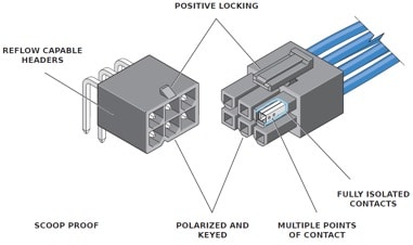
Figure 4: Connectors between the MOSFET/IGBT power-driver stage and the motor must be chosen to handle the higher voltages and currents associated with delivering power. The Molex FiT Connector family pictured is available in five sizes and capacities, with features designed for reliable, safe, and approved interconnects at these higher levels. (Source: Molex)
All connectors in the family have the same shape but differ in physical size. They are polarized and keyed, include positive locking to avoid accidental disconnect, and are designed to prevent touching of the contacts. To enhance reliability and also reduce contact voltage drop and power loss, each interconnect has multiple points of metal to metal contact.
Conclusion
Reference designs and evaluation boards for robotic systems are more essential than ever for meeting time-to-market goals for complicated and ambitious applications. As motion control and robotics increasingly becomes an all-electric/electronic function with less need for of pneumatic-driven prime movers, IC suppliers are able to step in and support start-to-finish hardware and software designs at system and subsystem levels. As a result, engineers doing projects in these areas have a wide range of options for assessing their motion-control problem and the solution paths to pursue.