Real-Time Challenges and Opportunities in SoCs
Featured Products
Resources
Advanced process technology and system-integration provide the driving forces behind silicon convergence. FPGAs speed along this trajectory, having already integrated SRAM memories, digital signal processing (DSP) and multiplier blocks, serial transceivers, memory controllers, and advanced I/O functions. The latest advancement in programmable technology is the SoC, which integrates an Altera® FPGA with an ARM® applications processor, plus a rich peripheral processor subsystem. The convergence of these technologies provides new challenges and opportunities for real-time embedded system design.
Introduction
This white paper explores an advanced motor drive or inverter application to illustrate how silicon convergence affects real-time design. Before the advent of highly-integrated solutions, each of the four major functions in the drive, shown in Figure 1, employed its own processor or DSP block, each with its own instruction set and development environment. For example, the motor control may employ a simple 32 bit processor. The networking interface may enlist its own 32 bit processor. Above all, safety features have top priority to ensure that system does not cause injury to itself or its operators.
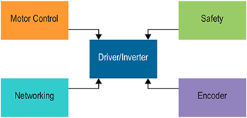
Figure 1: The Four Basic Functions of a Motor Drive/Inverter.
Thanks to silicon convergence, all these motor drive functions now combine into a single, cost-effective, programmable SoC. As with most advanced real-time systems, this system:
- Gathers signals from each of the four major functions.
- Processes these signals to extract relevant data.
- Applies computationally intensive analyses to make data-driven decisions.
- Acts to implement the decisions, all subject to maximum-latency requirements.
This same real-time processing model appears in other diverse applications such as automotive driver assistance, real-time financial trading, and guidance systems.
Challenge—Doing Ever More in Less Time
System responsiveness is a driving force in real-time applications. How quickly and consistently can a system respond to real-time events? Can the system perform its necessary tasks within a specific, bounded time, every time? Embedded engineers continually seek to perform ever more sophisticated functions and calculations but in less total time.
Initially, the embedded hardware performed simple proportional-integral-derivative (PID) motor control. Over time, motor control became more sophisticated to include model-based motor control solutions, as shown in Figure 2. Motion-adaptive motor control allows the system to intelligently adapt to changing systems conditions and retune control parameters based on sensor feedback. Lastly, in a factory automation environment, multiple motors communicate to coordinate their response and complex movements. For example, a safety-related exception may trigger a shutdown sequence that requires coordinated movements of a variety of equipment to protect both the operator and downstream machinery to minimize system downtime. Naturally, all of this sophisticated computing happens in ever-decreasing amounts of time.
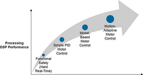
Figure 2: Embedded Applications Asked to Do Ever More in Less Time
As the algorithms grow in sophistication, they also require more computations, larger data sets, and more DSP power. The location of stored data and the communication bandwidth to that data has major implications and directly affects system responsiveness.
Challenge—Scheduling Conflicts
Scheduling conflicts are another inevitable challenge in real-time system design. In traditional design approaches, each of the four major motor drive functions shown in Figure 3 has its own dedicated processor and each essentially operates independently. In a converged solution, these four functional groups are combined into a single system but each still operates asynchronously. Potential scheduling conflicts occur because all of the interrupts are routed to a single device. If not handled properly, the random and asynchronous nature of the interrupts potentially causes scheduling clashes within the application program, resulting in decreased responsiveness. Managing jitter and ensuring more-deterministic behavior are key factors to avoid schedule conflicts.
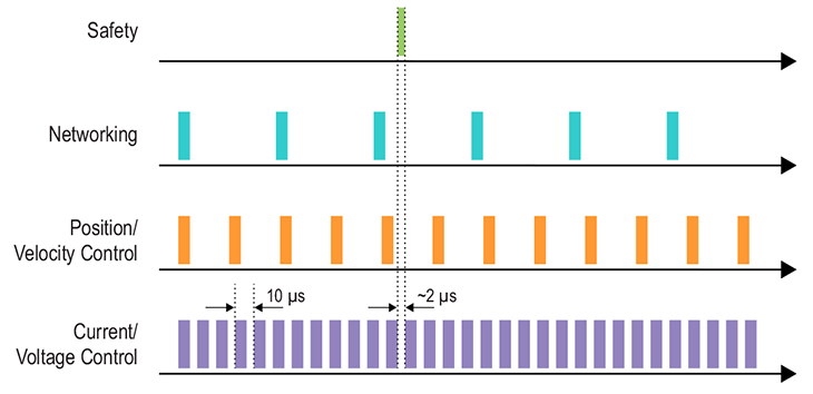
Figure 3: Motor Drive Application
If the entire motor drive application is integrated within a single processor, the majority of its computing time is spent performing the current control loop, shown in green in Figure 3. Meanwhile, as the system performs its various other motor control and networking functions, a safety event may be triggered within the system. The system must detect the fault condition, diagnose it, respond immediately to take the appropriate safety action, and shut down gracefully because safety has the highest overall priority. How fast the system can actually respond is key.
Measuring System Responsiveness
How is real-time responsiveness measured? Responsiveness consists of two elements:
- Interrupt latency—Once an event happens, how quickly can the system recognize it? For processor- or DSP-based applications, the interrupt latency (I) is the period from the moment an interrupt is asserted to the instant that the processor completes its currently executing machine instruction and branches to the first line of the interrupt service routine (ISR).
- Execution time—After the event is recognized, how quickly can the system process it? For processor- or DSP-based applications, execution time (E) is the amount of time required for the processor to complete all the instructions within a particular ISR and then return to normal operation.The total response time adds the interrupt latency to the interrupt execution time (I + E), as illustrated in Figure 4.
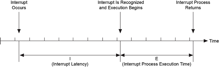
Figure 4: Interrupt Latency and Process Execution Time
Real-Time Processors and Tools
Altera's programmable technologies provide unique capabilities to speed algorithms and opportunities that improve a system's real-time response. Time-critical algorithms can be efficiently partitioned between highly parallel hardware solutions implemented on programmable logic elements (LEs), DSP blocks, or software solutions executed on one or more hard or soft processors
Altera's real-time processors and tools, summarized in Table 1, enable embedded system designers to explore hardware/software tradeoffs and to develop new solutions that meet demanding real-time performance challenges. The solution to meet real-time challenges lies within the careful partitioning of real-time algorithms between hardware and software implementations across Altera's real-time processors and tools, which comprise:
- Hard processors (ARM Cortex™-A9 processors)
- Soft real-time processors (Nios® II processors)
- DSP blocks (variable-precision hardware multipliers and accumulators)
- State machines (custom hardware using LEs within core fabric)
Table 1: Altera Real-Time Tools Components
| Solution | Interrupt Latency | Execution Speed | Data Sets | Derterminism | Design Method |
| ARM Cortex-A9 Processor | Moderate | High | Very large | Moderate | C |
| Nios II Soft Processor | Low (vectored interrupt controller) | Moderate | Large | High | C |
| DSP Builder + Intellectual Property (IP) | Low | High to very high | Limited | Very high (no jitter) | MATLAB/Simulink |
| Hardware-Based State Machines | Very low | Extremely high | Small | Very high (no jitter) | FPGA design, HDL tools |
Altera's ARM Cortex-A9-based hard processor subsystem (HPS) potentially improves real-time performance in systems where execution speed or throughput dominates the real-time response time. Exploiting asymmetric multiprocessing (AMP) techniques, one Cortex-A9 processor typically executes the operating system and main application program while the second Cortex-A9 processor is dedicated to the time-critical, real-time function.
Altera's Nios II soft processor utilizes the resources of the FPGA. The maximum clock frequency for Nios II processors is constrained by the core fabric performance of a given FPGA. For example, in Cyclone® V devices, 100 – 150 MHz Nios II processor clock rates are common. The Nios II processor offers some distinct advantages for real-time processing, including:
- Low interrupt latency thanks to a vectored interrupt controller.
- The number of possible Nios II processors in an application is limited only by the size of the FPGA fabric.
- A single highly time-critical function can be dedicated to a single Nios II processor, guaranteeing highly deterministic interrupt response times and freeing the ARM Cortex-A9 processor for other functions.
- Nios II processor has the ability to use on-chip memory as tightly coupled memory, which is useful to store critical real-time algorithms.
- Nios II processors have custom instruction interfaces that allow FPGA hardware based accelerators to implement a real-time function and return the result directly to the processor pipeline.
Altera's variable-precision DSP architecture provides the most powerful real-time performance in systems where matrix manipulations, filters, transforms, and DSP operations dominate the real-time response time. The highly parallel nature of the FPGA's programmable architecture plus an abundance of variable-precision DSP blocks coupled with block SRAMs delivers extreme performance for many applications. For example, Altera's Stratix® series FPGAs offer over 1 teraFLOPS (TFLOPS) of floating-point DSP performance, which greatly exceeds the performance of any ARM-based processor and only rivaled by high-end GPUs.
Altera's DSP Builder design software, a plug-in to the popular MATLAB/Simulink software, empowers designers to use model-based entry methods to generate RTL automatically and to evaluate tradeoffs between fixed-point and floating-point performance and dynamic range. Similarly, designers can unroll loops for maximum performance or fold them, allowing logic reuse that conserves FPGA resources.
Finally, for ultimate performance and determinism, the FPGA core fabric and adaptive logic modules (ALMs) provide fast, efficient hardware-based state machines. Via custom-crafted designs in VHDL or Verilog HDL, the FPGA can deliver unparalleled response times for specific applications and for applications with smaller data sets. However, the design engineer requires knowledge of HDL and the design constraints for timing closure.
Benchmark Example—FOC
The performance gains achieved from hardware/software tradeoffs are entirely application dependent and nothing highlights these effects better than a real-world benchmark example. This motor-control benchmark example uses field-oriented control (FOC), shown in Figure 5, where the algorithm consists of two types of control loops. The outer control loops measure the position and velocity of the motor and requires low processing rates, making it ideal for traditional processor-based solutions.
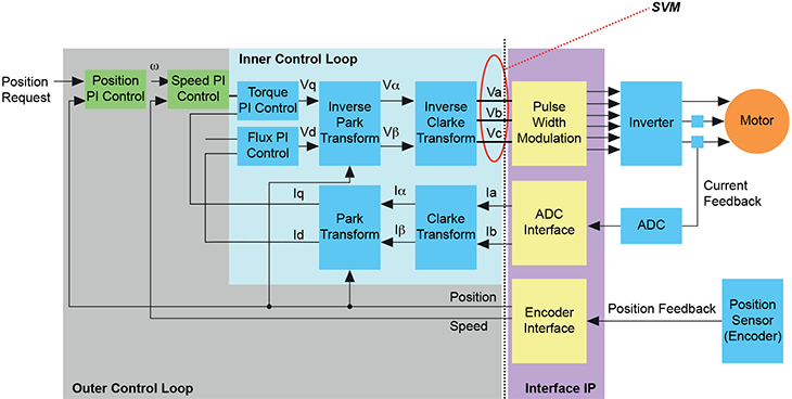
Figure 5: FOC Benchmark
In contrast, the inner control loop is far more computationally complex and demanding. Relying on current feedback measurements from the motor, the inner control loop calculates torque and flux using Park and Clarke data transforms and their inverse operations. The resulting torque and flux calculations ultimately produce a space-vector modulation (SVM) value that drives the motor. The inner loop operations require much higher processing rates and are computationally complex. This benchmark example is implemented using the following hardware versus software solutions available in an SoC:
- Implement the FOC benchmark solely using the ARM Cortex-A9 processor using C code.
- Implement the FOC benchmark solely using a Nios II soft processor using C code.
- Apply hardware acceleration techniques that leverage FPGA-based Nios II processing and DSP Builder.
- Explore fixed-point vs. floating-point solutions.
- Explore solutions with unrolled and folded critical loops.
Finally, the resulting solutions are compared and contrasted for their real-time response and deterministic behavior.