Don't Ignore the Humble Brushed DC Motor
By Bill Schweber for Mouser Electronics
"This ‘ancient’ motor arrangement has been overshadowed by the brushless DC motor, but it remains a viable solution for low-end, cost-sensitive applications."
In these motors, the switching of the orientation of the magnetic poles—the commutation—was done by movement of a fixed-in-place contact that "brushed" against electrical contacts on the motor rotor. This fixed contact was often made of graphite that, unlike copper or other metal, would not fuse or weld to the associated rotating contact during high-current short circuits or break/make action, and it was often spring-loaded for consistent contact pressure.
Due to the enormous role that medium and large BDC motors played in the industrial and technological advances of the 20th century, DC motor theory and practice were extensively analyzed by luminaries such as Charles Steinmetz. This included detailed circuit, electromotive-force and magnetic-field equations; performance parameters (speed, torque, control and efficiency); and design, fabrication and practical considerations. Courses in DC motor theory and application were a standard part of nearly all engineering programs for many decades, including full-scale, hands-on lab sessions with small and large motors.
The dominance of the brushed motor declined beginning a few decades ago as solid-state motor switches using MOSFETs and IGBTs and controls became practical, cost-effective and reliable. In their place, brushless DC (BLDC) motors and their siblings, such as stepper motors, became the dominant DC motor. Today BLDC motors are used by the countless millions in cars, disk drives and printers, small- and medium-sized appliances, and more.
The reasons for this shift are clear: advanced electronics using these switches, drivers and smart controllers yield motor systems that are much better in terms of efficiency, reliability, electrical noise, controllability and versatility. These BLDC motors have no brushes to wear out or cause EMI/RFI. As a result, the use of BDC motors has fallen dramatically as brushless alternatives have replaced them.
Despite the enormous shift from brushed to brushless motors, there are applications and situations where the brushed version is the best choice in terms of adequate performance, low cost and sufficient reliability. These include not only inexpensive toys but even straightforward functions such as seat adjustment controls in cars.
Further, when combined with the latest controllers and MOSFET/IGBT switches, they can provide sufficiently good performance as long as their limitations are well understood. Because they require few or no control electronics, the overall motor/control function can be fairly inexpensive. Also, a basic BDC motor needs just two wires between the power source and motor, which saves space otherwise required for wiring and connectors in tight situations and reduces cable and connector cost.
Brushed Motor Basics
All motors (with some unique exceptions, such as piezoelectric motors) depend on the interaction between an electromagnetic (EM) field on the fixed body (the stator), the EM field on the rotating armature (the rotor) and how these fields are controlled and changed to induce magnetic attraction/repulsion and thus motion, Figure 1 and Figure 2.
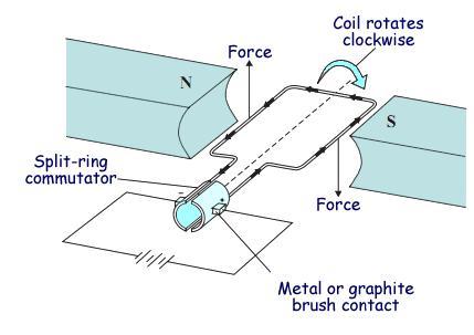
Figure 1: A conceptual arrangement of the brushless DC motor shows the interaction among the external magnetic field (here, supplied by permanent magnets), the brushes, the commutator on the armature and actual rotation. Image source: http://www.cyberphysics.co.uk
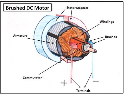
Figure 2: An actual brushed DC motor has extensive coil windings on its armature; these generate the strong magnetic field that interacts with the external magnetic field (here, provided by permanent magnets. Image source: Clemson University
The basic brushed motor is entirely mechanical with no electronics required. Control, to the extent possible, is simple: connect the DC source, and the motor self-starts and then rotates; there is a potential start-up problem due to a small contact angle "dead zone," but that can be solved with some mechanical design adjustments.
To reverse the direction of rotation, just reverse the DC power leads; to adjust the speed (within a limited range), increase or decrease the DC voltage. In general, the speed (revolutions per minute, RPM) of a BDC motor is proportional to the electromotive force (EMF) in its field coil (EMF is the voltage applied to it minus voltage lost due to its resistance), while the torque is proportional to the current being drawn.
So how does the brushed motor develop the rotating field needed to force the armature to rotate, but without an external controller? The motor does it for itself. A pair of brushes located 180° apart on the motor housing directs the applied current to the armature coils via two commutator contacts (plates); each of the plates covers nearly 180° of the armature. As the motor turns, the current's flow path between the source, the brushes, the commutator plates and the two motor coils (windings) automatically switches every half-turn.
The magnetic field of the armature interacts with the magnetic field of the rotor, which can be produced either by fixed coils on the motor body or by permanent magnets. As the rotor turns, its magnetic field reverses and thus the motor keeps turning, because the field developed by the coils is switching and is attracted/repulsed with reference to the field generated by the external coils or permanent magnets.
Note that for many years, the use of permanent magnets was only practical for tiny motors, such as in toys, because the magnets were not powerful enough for a reasonable size and weight. However, the development of high-energy permanent magnets using rare earth materials changed that, making PM-based BDC motors viable for larger motors—even in the fractional-horsepower range. While the PM approach is more efficient as no power is needed for the external field coil, it reduces the degrees of freedom that the system has in controlling the motor behavior. Whether a PM BDC motor or the field coil design is a better choice involves tradeoffs in size, cost, weight, control needed and other factors.
Beyond Brushed-Motor Basics
In basic form, the BDC motor is the model of elegance and simplicity. In fact, many basic science kits for youngsters use a simple brushed motor to demonstrate basic electrical and magnetic principles, and how their interaction can be used to produce useful motion, Figure 3. There are no electronic components, and all the action and current-flow path are visible.
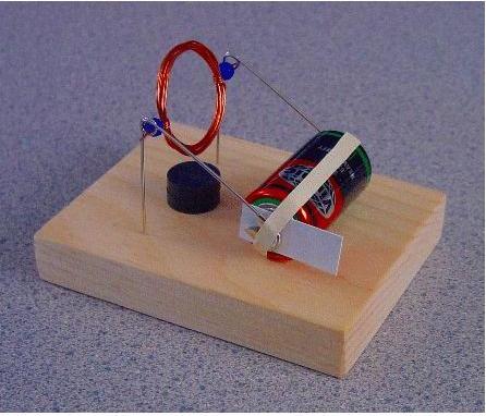
Figure 3: A motor cannot be simpler than this student-project version, which uses a permanent magnet for the external (stator) field, paper clips for the brushes, and a small coil of wire for the armature winding; it operates directly from a battery.
The simple, basic BDC motor discussed is just that: simple and basic. However, given the many applications and sizes of these motors over the 100+ years, they have been in use, numerous variations have been devised to either overcome some weakness or optimize performance in a specific application. Many of these are centered on the windings of the field coils of the stator or the coils on the armature. Other variations permanently or temporarily add capacitors and resistors to adjust voltages, limit current, or shift the relative voltage/current phase relationship.
In practice, most DC motors have more than just the two armature poles of the simple version. Among other benefits, adding more poles allows the motor to more reliably start from any rotational angle (the simple version has two small dead zones). Also, there is no position in which current can flow even momentarily through a short circuit; some systems can tolerate a brief short circuit twice per revolution, while many cannot accept this.
The field coils of the stator can be wired in several configurations, Figure 4. The most common arrangements are series wound, shunt wound and compound wound (a combination of series and shunt). In a series-wound motor, the field coils are connected in series with the armature coils (via the brushes); in a shunt-wound motor, these field coils are instead connected in parallel ("shunt" is another term for a "parallel" connection) to the armature coils.
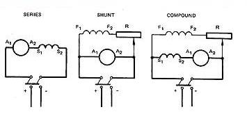
Figure 4: (left to right) In the series-wound configuration, field coils S1-S2 are wired in series with armature coils A1-A2; for shunt wound, the field coils F1-F2 are in parallel with armature coils A1-A2; for the compound approach, field coils S1-S2 are in series and F1-F2 are in parallel with the armature coils A1-A2. Image source: http://www.industrial-electronics.com
Each wiring configuration gives a different balance of control and performance of speed versus torque, starting and running torque, and ability to handle changes in load. Some advanced designs use independent excitation control for the field windings of the stator and the armature windings of the rotor, for more flexibility and tighter control.
Brushed Motors Advance into The 21st Century
Despite the many virtues of BLDC motors, brushed motors are still available and are being enhanced. While the basic motor design is relatively unchanged in many ways, there are two significant developments: the widespread use of permanent magnets rather than field coils, and the use of ICs and electronic switching for the coil-drive and feedback functions.
The Digilent 290-008 is an example of a basic 6-V BDC motor, Figure 5. It includes a 1:53 reduction gearbox for improved torque, rated at 0.7 kgf-cm (maximum). Although the power connection needs just two leads, the motor/gearbox comes with a six-lead connector. The other four leads are for the integrated Hall-effect sensor pair, which is used to indicate revolutions and direction, using the standard A-B quadrature approach.
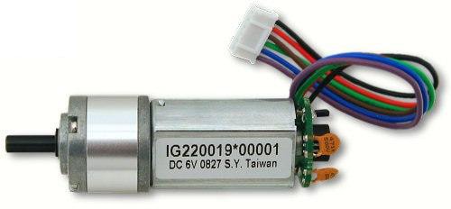
Figure 5: Digilent's 290-008 6-V DC motor is a good example of a basic brushed motor; it requires only plus and minus leads for power but also includes a pair of Hall-effect devices and four additional wires for sensing rotation and direction, needed for feedback control. Image source: Digilent
Free-running, no-load current for this motor at 6V is 220mA at a speed of 150RPM; the full-load rated current is 480mA at 125RPM and stall current is 1.8A with a torque of 4.1 kgf-cm. Coil resistance of this small motor plus its gearbox (54mm long with a 22mm diameter, plus connector) is just 3.3Ω. The performance graph, Figure 6, shows the interplay among five key parameters (with a 6-V supply): 1) torque, 2) speed, 3) current, 4) output power and 5) efficiency.
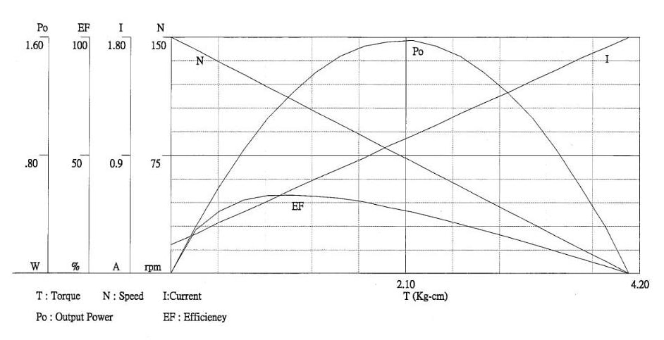
Figure 6: This one graph shows all the dominant operating parameters of the Digilent 290-008 motor and how they vary across the entire operating range. Image source: Digilent
Although a brushless motor can operate directly from a DC rail, there are advantages to using a "proper" driver component to provide not only the requisite drive current, but also the various protection functions that almost every motor subsystem requires. The Texas Instruments DRV8412 Dual Full-Bridge PWM Motor Driver, a member of its broad DRV8x family of integrated motor drivers, handles two independent brushless motors (and stepper motors as well). It features high-efficiency drivers (up to 97%) to minimize thermal dissipation and associated issues, Figure 7, and can deliver 2 × 7A (continuous) or 2 × 12A (peak) to the motors.
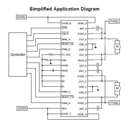
Figure 7: The DRV8412 Dual-Motor Driver from Texas Instruments not only handles two independent brushed motors, but also provides critical protection against various fault, thermal and over-current conditions. Image source: Texas Instruments
The tiny IC (just 14.00mm × 6.10mm) has a protection system that safeguards the device against a wide range of fault conditions that could damage the system. These include short-circuit protection, over-current protection, under-voltage protection and two-stage thermal protection. It also has a current-limiting circuit that prevents device "false" shutdown during load transients such as motor start-up (roughly analogous to using a slow-blow fuse rather than a quick-acting one). A programmable over-current detector allows adjustable current limit and protection level to meet different motor requirements.
Members of this family have independent supply and ground pins for each half-bridge, which enables current measurement through external shunt resistors and supports the use of multiple motors with different power-supply voltages. This is useful when the two motors serve different sizes, thus requiring different supply voltages, such as in an advertising display with a very small motor to wave an attention-getting flag on a display, and a larger motor to rotate the entire display.
Summary
There is no doubt that DC-powered brushed motors have been overtaken to a large extent by electronically controlled brushless motors, for many solid technical reasons. Nonetheless in less-demanding, cost-sensitive applications or situations with limited requirements, the brushed motor can be an effective solution. By combining a brushed motor with a basic motor driver IC, the brushed motor and the end product can realize many additional operating and protection benefits. It is shortsighted to automatically assume that brushless is the right choice without at least looking at the design objectives and the attributes of the BDC motor.