High-Performance Drivers for Motor Control
By Maurizio Di Paolo Emilio for Mouser Electronics
Electric motors represent an essential component in the industrial sector, where they are used for fans, pumps, and other types of machinery in a wide variety of applications. The traditional AC motors that have been around for over a century are the simplest types of induction motors, but they can waste a significant amount of energy. DC motors are a class of rotary electrical machines widely used in various applications. A DC motor's speed can be controlled by modulating the voltage according to the needs of the application. This can save significant energy since the motor only works as much as the situation requires.
Features of electric drives
An electric motor is a "reversible" machine capable of transforming electrical energy into mechanical energy. The term reversible indicates that it can do the inverse operation, changing its name to Generator. Conceptually, and often also practically, the two are the same thing. A fixed (stator) and mobile (rotor) part always constitute a motor. The various types of motor are distinguished from each other by how the magnetic fields are generated:
- Continuous Motors (DC): static field, generated by magnets or by windings in the stator; they are available in a wide range of voltages; the most popular being 12V and 24V.
- Alternate Motors (AC): dynamic field, generated by the interaction between fields generated by the currents and rotor. The rotation of the rotor is synchronised with the frequency of the supply current (Synchronous AC motor).
- Brushless motors: static field, generated by rotating magnets which are fixed on the rotor.
In DC motors, the generation of the magnetic field is carried out by the stator. The magnets can be permanent (ferrites, for example) in low-power motors, while they are generated by dedicated windings in the medium and large power motors, also called the wound field. The power is brought to the rotor by rotating collectors and brushes that are subject to wear. They have excellent characteristics of robustness and reliability. The motor speed is controlled by adjusting the DC voltage applied to the armature winding. Depending on the application, a full-bridge converter, half-bridge or just a pulse width modulation (PWM) converter is used.
DC motors are also widely used in servo applications where speed and accuracy are essential. To meet design requirements regarding speed and accuracy, microprocessor-based closed-loop control and information on the rotor position are crucial. Maxim's Hall effect MAX9921 sensor provides information on the rotor position. A Hall-effect sensor is a transducer that varies its output voltage in response to a magnetic field. The Hall effect sensor is composed of a sensitive element coupled to a magnet contained in an airtight container that detects the variation of the magnetic field flux when a ferromagnetic material body (metal projection) is approached and moved away.
The device can work ideally from zero frequency up to a few kHz. Hall effect devices are used as proximity sensors, positioning, speed and current sensing. Unlike a mechanical switch, it is a long-lasting solution because there are no mechanical wear problems.
The DC brushless motor (BLDC) is a direct current electric motor with a permanent magnet rotor and a rotating magnetic field stator. Unlike a brushed motor, therefore, it does not require sliding electrical contacts (brushes) on the motor shaft to operate. This means less mechanical resistance and less opportunity for sparks forming, and a considerable reduction of maintenance.
A very similar motor is the stepper motor, which differs from the brushless motor in that the stator is not powered all the time, but cyclically supplies the various electromagnets to generate a rotation or obtain a precise position. In a brushless motor, the rotor is non-winding and instead has permanent magnets, while the magnetic field generated by the windings on the stator is variable.
Since the motor operates in direct current, to realise the rotation of the magnetic field generated in the stator, an electronic circuit composed of a bank of power transistors controlled by a microcontroller that controls the switching of the current, commands the current inversion and therefore the rotation of the magnetic field.
Since the controller must know the position of the rotor concerning the stator to determine the orientation of the magnetic field, it is usually connected to a Hall effect sensor. The efficiency of these machines is on average higher than the asynchronous direct current motors (Figure 1).
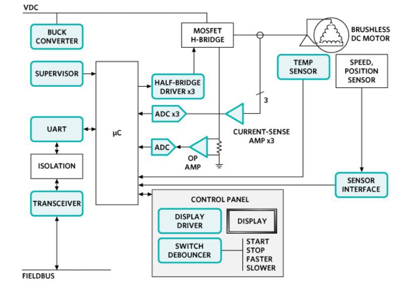
Figure 1: Block diagram for brushless motor control. (Source: Maxim Integrated)
BLDC motors are a particular type of synchronous motor. This means that the magnetic field generated by the rotor and the stator have the same frequency. The BLDCs are subdivided into three categories: single-phase, 2-phase and 3-phase. The number of phases corresponds to the number of windings on the stator.
Motor Drives
The motor driver covers a wide range of applications in the most different industrial and civil sectors, particularly in electronic instrumentation and various computer peripherals. Each application has a different requirement of power and characteristics to be satisfied, for example, speed, piloting, torque control. Position or speed adjustment are some requirements that a control system must manage; to cope with these characteristics on the market, we find a series of control modules for DC motors and steppers. The DC motor finds space in automation and robotics; the operating principle is based on the interaction of two magnetic fields that create attraction and repulsion (stator and rotor). The stepper motor finds space in precision applications and requires pulses to be driven. The servomotor, on the other hand, is an electromechanical system equipped with a mechanical part and a feedback electronics for driving; it requires an appropriate control system to carry out particular operations.
Driver ICs
Designers are faced with increasing pressure to improve design efficiency further and stand out in the competitive market. This can be achieved, for example, by reducing overall energy consumption and optimising thermal management. The primary function within the motor is switching, applying a current through the motor windings at precisely the right time. Switching is controlled by algorithms that reside on a microcontroller or digital signal processor (DSP). The motor control algorithms are generally very sophisticated as they have to make the right switching decisions under different engine load conditions.
Features that simplify projects include integrated power MOSFETs and an ultra-low power supply architecture that provides integrated current limitation and flexible current regulation mode. Monitoring and safety functions such as overvoltage, short circuit and over-temperature protection, together with fault diagnostics, ensure high performance.
The MAX14871 full-bridge driver offers a low-power solution for voltages between 4.5 V and 36 V. This driver reduces power dissipation and provides a charge-free design for reduced external components and low current supply. Integrated current control requires minimal external components and includes three adjustment modes (Figure 2).
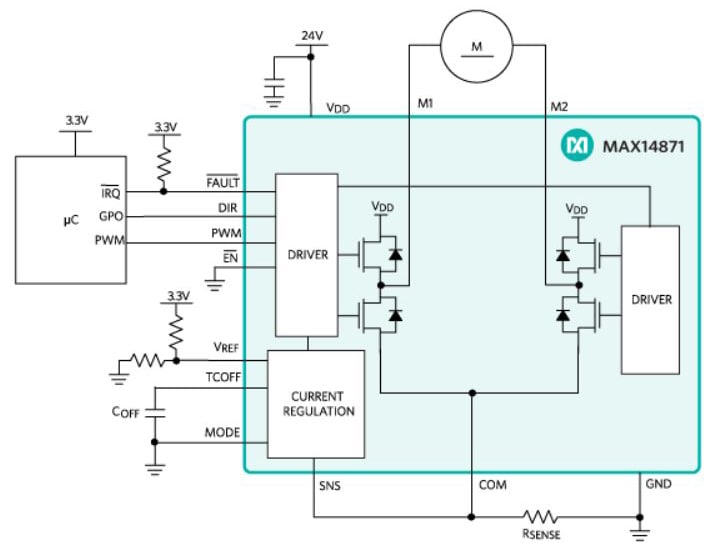
Figure 2: Block diagram and circuit application for the MAX14871. (Source: Maxim Integrated)
Given the increasing need for energy saving and silent running of the motor in various applications, brushless DC motors (BLDC) are suitable for a wide range of situations. To improve efficiency, Toshiba's controllers take advantage of InPAC (Intelligent Phase Control) technology. Toshiba's InPAC technology compares the relationship between the current phase (current information) and the voltage phase (Hall effect signal) and provides feedback to the motor current control signal to automatically adjust the phase. Toshiba TC78B0 integrated circuits are designed to control the rotation speed of the motor by modifying the PWM work cycle. These devices are equipped with three-phase full-wave drive, sinusoidal PWM drive, overcurrent detection circuit and thermal shutdown circuit.
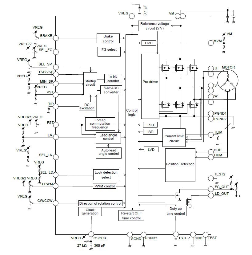
Figure 3: Block diagram for the TC78B015FTG. (Source: Toshiba)
TC78B015FTG operates with a power supply between 6V and 22V while the model TC78B015AFTG requires a power supply from 6V to 30V. Both devices support output currents up to 3A and support Hall-effect devices, as well as offering a range of protection features including thermal shutdown, overcurrent detection and motor block detection (Figure 3).
ON Semiconductor offers its driver STK984-090A for three-phase brushless DC motor made up of a power MOSFET. STK984-090A-E has an integrated shunt resistor and thermistor. Various protective functions are incorporated against over-temperature, over-current, over-voltage and low voltage. The BLDC motor drive circuit can be efficiently designed with a reduced PCB area (Figure 4).
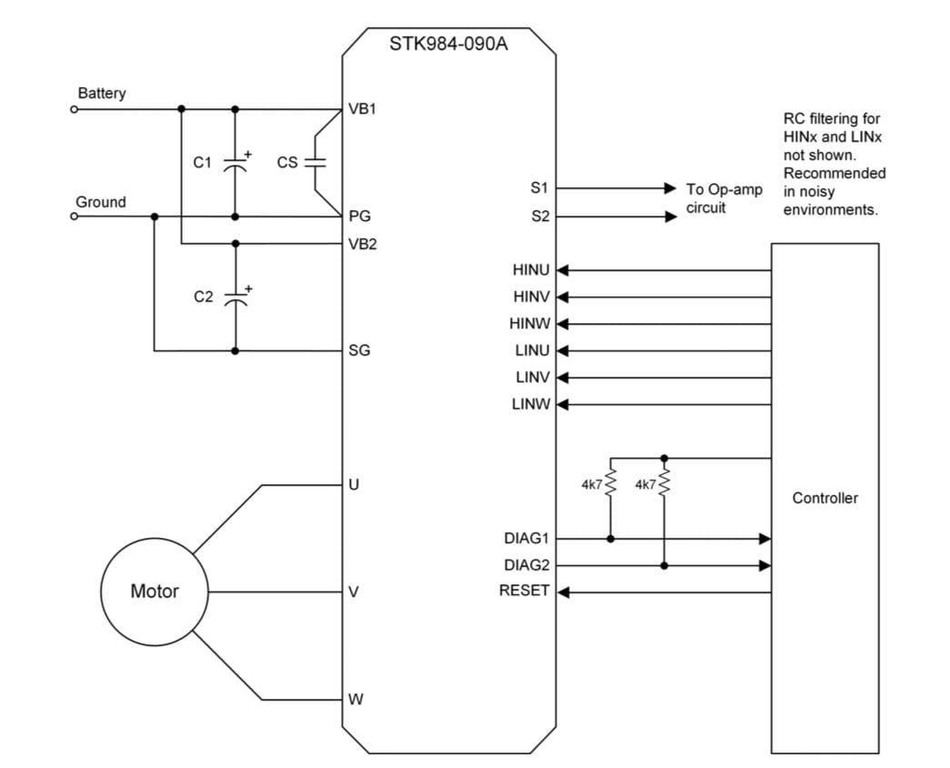
Figure 4: Application schematic for the STK984-090A. (Source: ON Semiconductor)
In order to reduce size and weight in motor drive applications, Texas Instruments has brought DRV832x gate drivers to the market. These drivers are based on an intelligent gate drive architecture that eliminates lots of traditional components. The drivers allow the control current to be set to optimise power loss and electromagnetic compatibility. The drivers are offered with or without a buck regulator or with three integrated current shunt amplifiers. Each option is available in versions with a serial diagnostic interface (Figures 5 and 6).
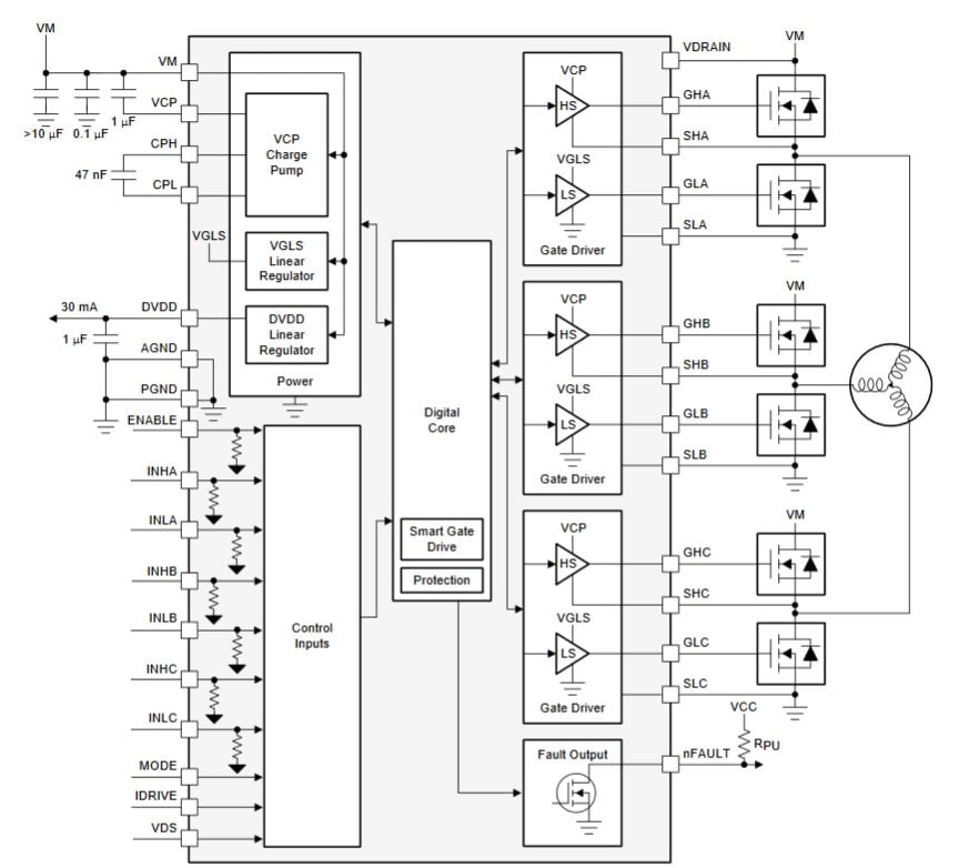
Figure 5: Block diagram for the DRV8320H. (Source Texas Instruments)
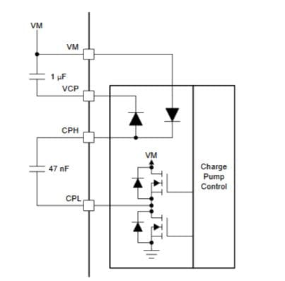
Figure 6: Charge pump architecture for the DRV832X. (Source Texas Instruments)
Conclusion
BLDC motors offer many advantages over traditional ones. The development of powerful magnets has enabled the production of BLDC motors capable of producing the same power as brushed motors but with a smaller footprint. Motor control offers the possibility of improving efficiency during the design phase. Understanding the control needs of each type of engine and the most appropriate style for a given application can help ensure greater efficiency in any context. Modern microcontrollers with gate drivers are perfect for providing the level of performance and computational functionality needed to develop high-efficiency control loops. Motor control in industrial projects is essential, mainly when used in robotic systems and numerical control machines, as well as in a whole series of precision drives.