Do Power Supplies Need Isolation?

Image Source: Natalia/Stock.adobe.com; generated with AI
By Alistair Winning for Mouser Electronics
Published September 18, 2024
A significant differential often exists between the voltages and currents used in a power supply and those used in the rest of the circuit. For example, the power supply circuit may take a 110V/220V mains voltage and cut it down one or more stages to between 1V and 5V for powering ICs. These voltage differences also appear inside multistage power supplies. Typically, different power domains must be kept apart for several reasons, such as prohibiting the high-power circuit interference from affecting low-power signals and protecting users from large currents if the circuit malfunctions.
Choosing Isolation
At some point, power supply designers must decide whether the power supply circuit should be physically separated and, if so, what type of isolation barrier to implement. In many cases, that decision is already addressed by standards such as IEC 60601-1:2005, which mandates circuit protection requirements for medical devices. Organizations like Underwriters Laboratories (UL), the Institute of Electrical and Electronics Engineers (IEEE), and the International Electrotechnical Commission (IEC) are responsible for setting these standards that dictate specifications such as clearance distances, isolation voltage levels, and insulation resistance. They also prescribe testing procedures to ensure the standards are met.
However, there are some good reasons to use non-isolated power supplies. Since they don’t require as many components, they are usually smaller and cost less than isolated supplies, especially since the components that provide the isolation barrier, such as transformers or optocouplers, are typically bulky. Non-isolated supplies can also be more efficient because they don’t have any extra components to power, and they don’t suffer from transformer losses. However, designers should be aware of the dangers and take precautions to prevent safety hazards, like ensuring that users are unable to interact with the system in a way that presents a risk of shock. Therefore, non-isolated power supplies are often found in low-power applications or supplies that are only accessible to trained personnel.
Although isolated power supplies require more components, are larger, and cost more, there are some very compelling reasons for using them. Their inherently safe operation means that they can be used by untrained personnel. An isolation barrier can be used as a conduit for the sensing signal to provide more accurate feedback and control of the output. The isolation barrier also breaks ground loops, which can introduce unwanted noise and feedback into the circuit and potentially damage sensitive components. Isolating the input and output circuits by removing a common ground eliminates that risk, resulting in a more stable power supply with a cleaner output.
Independent output circuits in power supplies can also enable flexibility through floating outputs and level shifting (Figure 1). In a supply with floating outputs, the output voltage is fixed between terminals. However, because there is no common ground, that voltage is not defined in relation to other parts of the circuit. The power supply outputs can be configured to provide positive and negative voltages based on the system's needs. Floating output voltages can also be connected in series to generate higher voltages. A simple implementation involves a power supply with a single AC-to-DC conversion stage, followed by two or more isolated DC/DC converters to achieve the final voltage. The outputs of the DC/DC converters are then combined to produce the desired values.
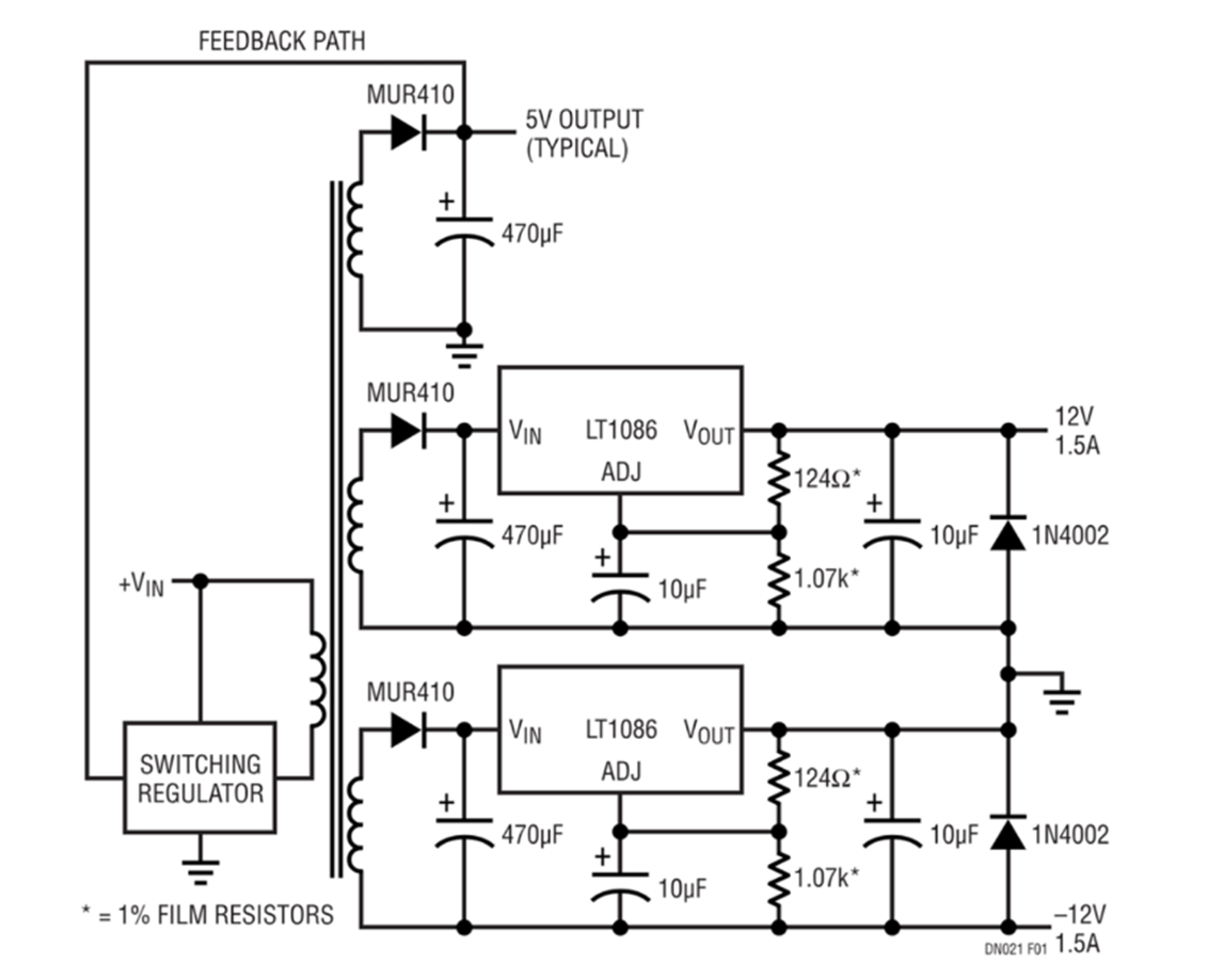
Figure 1: Isolation in the power supply enables floating outputs that can be combined to provide negative voltages. (Source: Analog Devices)
Implementing Isolation
If the circuit requires isolation, the right choice of technology and components will depend entirely on the application. There are several important parameters that need to be considered. These include isolation withstand voltage—the amount of voltage that the isolator can withstand for 60 seconds without breaking down—and the actual working voltage of the circuit. Common mode transient immunity (CMTI) is needed in noisy environments to ensure data integrity, as well as in circuits with fast-switching devices. CMTI prevents high-power noise from coupling past the isolation barrier and generating a current loop. Creepage (distance between two conductors along the shortest physical path) and clearance (shortest distance between two conductors through the air) are also important considerations, and some regulations mandate minimum values for each. In applications that require strong levels of isolation and higher values for creepage and clearance, larger packages often provide a solution.
Designers can achieve power supply isolation in several different ways, the most common being optical, capacitive, and magnetic isolation.
Optical Isolation
Optical isolators work by using an LED to turn the electrical signal into a light source and sending it through a translucent material to the other side of the isolation barrier, where a phototransistor turns it back into an electrical signal. Optocouplers, also known as optoisolators, can provide isolation at levels up to several kilovolts, have an acceptable lifetime, provide good response times at lower frequencies, and are resistant to electromagnetic interference (EMI) and other noise (Figure 2).

Figure 2: Optocouplers convert electrical signals to light and back again to isolate one circuit from another. (Source: sketch stock/stock.adobe.com)
However, LEDs need to be biased in order to operate in optocouplers, which wastes energy. The isolation barrier can decay over time, meaning designers must allow more headroom to account for degradation. Optocouplers also offer poor response at high frequencies and flawed linear response to input and output current changes.
Because of light interference between channels, optocouplers tend to be fabricated with a single device in each package, adding to the component count, size, and cost. However, most of these drawbacks are not a big problem for power applications, as they generally require only a single feedback-sensing signal and the frequencies used are lower than in many other applications. Optocouplers have also recently become available with several lines in a single package.
Magnetic Isolation
Magnetic isolation uses a transformer, in which the primary winding is energized to create a magnetic field that induces a current in the secondary winding. Both winding coils can be wrapped around a magnetic core but isolated from each other.
Transformers are already used in some voltage conversion topologies to step the voltage up or down or to provide multiple outputs. The transformer itself provides isolation, and magnetic isolation can be achieved through that single component. Feedback can be obtained when the transformer is in its “off time” with no current flowing, as it is then possible to sense the reflected voltage from the secondary side, where the output voltage is delivered.
The system controller can then use that feedback to alter the output if required. The controller, which can be a microcontroller or a bespoke device, is responsible for ensuring the output signal is stable. Real-time information on the actual output value of the system allows it to do that more accurately. This type of circuit can lead to some small and cost-effective solutions because of the few components needed (Figure 3). However, it has a few drawbacks: It requires at least a small load for the current to flow and the sensing to work; and although the regulation is generally acceptable, it is not as good as a circuit with a dedicated isolated feedback path.

Figure 3: This simple flyback converter uses the Analog Devices LT830X controller to sense output voltage through the system transformer. (Source: Analog Devices)
Other applications may require tighter regulation or operate without a load for periods of time. In these types of applications, a separate transformer can be used to provide feedback from the output while blocking unwanted signals. These magnetic isolators (Figure 4) are usually available in a single package and can often incorporate other parts of the system in the same package to save on cost and board space. They can be found in configurations suitable for the most commonly used power topologies, including flyback and active-clamp forward controllers. Integrated solutions can also contain a range of protection features, such as overcurrent and short-circuit detection.

Figure 4: Magnetic isolation separates different areas of the circuit using a transformer. (Source: Analog Devices)
Magnetic isolators can isolate up to 1kV; they are fast and very robust, feature a large bandwidth, and their performance does not degrade over time. However, they can face some problems in applications with heavy EMI, such as motor drives.
Capacitive Isolation
As the name suggests, capacitive isolation uses two conductor plates separated by a dielectric material. The technique offers several benefits, including a high isolation figure, fast response, low power consumption, and good EMI immunity.
As with magnetic isolators, capacitive isolators can come in a single package or be packaged with other components. Some companies have developed integrated devices using silicon dioxide as the dielectric. This material is commonly used for insulation in IC production, allowing capacitive isolation to be implemented directly during the IC manufacturing process. In addition to providing isolation, using a normal manufacturing process to make the isolator produces robust components with good shock protection.
Conclusion
The decision to implement isolation in power supply designs hinges on factors such as safety, performance, and regulatory requirements. Isolation offers significant advantages, including enhanced safety for users, reduced interference, and improved stability of the power supply output. While non-isolated power supplies can be more cost-effective and efficient for certain low-power applications, the benefits of isolation make it indispensable for applications requiring high reliability and safety. Designers must carefully evaluate the needs of their specific application to determine the appropriate isolation method and ensure compliance with relevant standards.