Motors, Control Options Advance Robotic Opportunities
Most are aware of the classic robot of science fiction, but the real growth in robots is in self- and remotely guided machines. These robots perform specific, well-defined tasks like assembly-line work, surgical assistance, warehouse delivery/retrieval, and even dangerous tasks such as clearing mines. Today's robots can handle both highly repetitive tasks as well as complex functions requiring flexibility in orientation and action (Figure 1).
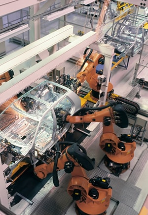
Figure 1: Robotics are now routinely used in applications ranging from small pick-and-place machines to large auto assembly lines where they lift, place, install, and even weld parts and subassemblies. (Source: IStockPhoto.com)
These high-performance machines are possible due to several advances: the sensors that help them hear, see, and feel; the computational power and sophisticated algorithms that enable real-time decisions and actions; and the motors that implement these decisions with speed, accuracy, and mechanical power. Each plays a vital role in robot design, because technological advances and the synergy among them rapidly builds on itself.
Traditionally, managing the motor has been a challenge for electronic engineers, since many critical issues are so different from those in the more-familiar electronics. Fortunately, technology has made these issues more understandable and easier to deal with, while also enabling impressive performance. For instance, Texas Instruments' DRV8816 dual half-bridge motor driver has integrated internal protection functions including short-to-ground protection, overtemperature warning, and overtemperature shutdown. A low-power sleep mode shuts down internal circuitry to achieve very-low quiescent current draw. Highly integrated controllers and drivers point to the level of flexibility and integration that electronics and motors have achieved.
Start with Motor Choices
There are three primary parameters that designers consider when selecting a specific motor type and model:
- The minimum and maximum motor speed (and associated acceleration);
- The maximum torque the motor can deliver, and the torque vs. speed curve;
- The precision and repeatability of the motor's operation (without using a sensor and closed-loop control).
Of course, there are many other performance factors involved in motor selection, plus size, weight, and cost factors. For nearly all small-to-moderate-sized robotic actuators, the most common choices for powering the actuator are the brushed DC, brushless DC (BLDC), and stepper motors. (However, there are some cases in which pneumatics and hydraulics are the best choice; see sidebar "Go with fluid power?".)
Brushed motors, the oldest DC-motor technology, are the simplest and least-expensive choice (Figure 2). The rotation of the motor's rotor switches (commutates) the field of the windings around the rotor via current-carrying brushes that make contact with the rotor. The motor speed is a function of the applied voltage, so the drive requirements are minimal, but managing the torque and associated position is difficult. They also have reliability issues due to the brush wear-out, may need maintenance as the brushes and their springs need cleaning, and are a source of electrical noise (EMI) due to the sparking at the contact point between the brush and rotor contacts as the rotor turns. For these reasons, brushed-DC motors are the least-attractive choice for robotics in most cases.
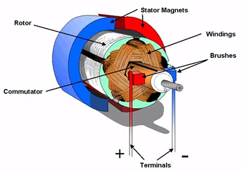
Figure 2: In the brushed motor, conductive brushes (which can be made of copper bristles or, more likely, graphite blocks) touch contacts on the rotor. As the rotor turns, it commutates and switches the polarity of the surrounding coil currents. (Source: Microchip Webinar)
Brushless motors (Figure 3) became practical beginning in the 1960s due to two developments: strong, small, low-cost permanent magnets, and small, efficient electronic switches (usually MOSFETs, but sometimes bipolar transistors with low-voltage drop) to toggle the current flow to the windings. The interaction between the stationary surrounding switched coils and the magnets on the rotating core replaces the mechanical commutation of the brushed motor with electronic commutation. The magnetic field of the coils is switched by turning the MOSFETs (usually configured in an H-bridge arrangement) on and off in a precisely timed sequence. By changing the frequency at which these MOSFETs are switched, the motor speed is controlled. In addition, the motor controller can sense the rotor position via a transducer, and as such, has tighter control over motor performance.
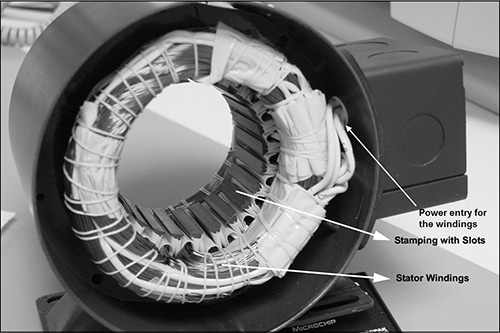
Figure 3: In the brushless motor, the coil currents are electronically switched in the stator windings while their magnetic field interacts with permanent magnets on a rotor. In this image, the missing rotor belongs in the center. (Source: Microchip AN885)
Even better, advanced algorithms such as PID (proportional-integral-derivative) or FOC (field-oriented control, sometimes called vector control) can be embedded in the motor controller. This matches the desired motor operation to the reality of the load and load changes, to provide enhanced performance. These algorithms can take into account factors such as the rotor's inertia, and adapt the motor drive to errors due to mechanical issues such as backlash or other sources. Using such algorithms provides the opportunity for precise control of acceleration and torque profile, in addition to speed setting.
Compared to brushed motors, brushless motors need more complicated control electronics but can deliver far better performance. BLDC motors usually require a feedback sensor, via Hall Effect devices, optical encoders, or sensing of back EMF. (Note that it is also possible to achieve some advanced control with traditional brushed motors by having a sensor for feedback, but their inherent design and electromechanical issues still limit their performance.)
Another brushless alternative is the stepper motor (Figure 4), which uses switched electromagnets arranged around a central core that is arrayed with a ring of permanent magnets. Step angles typically range from about 1.8â° (200 steps/rev) to 30â° (12 steps/rev), depending on the number of permanent magnets, but higher and lower values are available.
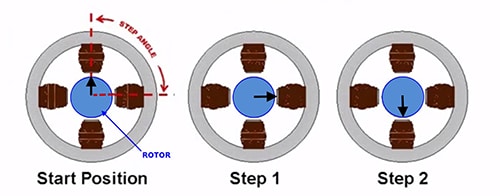
Figure 4: The stepper motor uses a ring of electromagnetic poles around a core with permanent magnets; by energizing these poles in sequence, the rotor is forced to turn. (Source: Microchip Webinar)
Steppers do not rotate in the normal sense; instead, the shaft is directed to move in finite, step-by-step increments and so can be directed to turn just a fraction of a complete revolution as well as to rotate continuously. If power is maintained but no stepping is directed, they will hold their position; steppers can provide high torque at low rpm. The most direct way to cause the stepper to move is to turn the electromagnets on or off in sequence, but this can cause chattering or vibration. To avoid this problem in situations where it is not acceptable, some advanced controllers support microstepping, where nearby windings are also energized in such a way that the stepping motion is smoother and more continuous than simple on/off control supports.
There is application overlap between BLDC and stepper motors. Steppers are better suited for applications that require precise back-and-forth motion, such as pick and place, rather than continuous rotation for long periods, and for smaller applications that don't require the motor to provide high torque or speed. Also, steppers are not as energy-efficient as brushless-DC motors.
There are many other motor options, as well. The family genealogy tree for motors is long and complex, with many siblings and cousins. For example, the permanent-magnet synchronous motor (PMSM) is a combination of a brushless-DC motor (with respect to the rotor) and an AC-induction motor (with respect to stator structure). It features high-efficiency, relatively high power in a small package, a high torque/weight ratio, fast-response times, and is fairly easy to control, but can be costly.
Control Requires Finesse
A motor alone, even with basic control of motor current, is not a robotics motion system, which consists of three major functional blocks (Figure 5):
- The real-time controller, which can be implemented in one of three ways: in a general-purpose, computationally fast processor running motion-control firmware; a DSP-oriented FPGA programmed for the control application; or via a dedicated controller IC with hard-wired, embedded algorithms.
- One or more driver stages in series, to take the low-level signals from the controller output and interface them to the higher-voltage/current needs of the electronic switches.
- The MOSFETs (or other switching element such as IGBT or bipolar transistor), which actually control the flow of current to the motor windings.
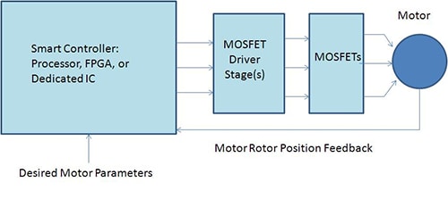
Figure 5: A complete motor-control chain has a smart controller for algorithm execution and calculations. The controller's outputs go to the MOSFET drivers, which in turn energize the motor's power-switching MOSFETs; many applications also have a feedback path that provides real-time information on the actual rotor position and thus can be used to determine velocity and acceleration as well. (Source: Bill Schweber.)
When selecting components, the choice of specific MOSEFT is determined primarily by the required current and voltage demands of the motor and its windings. While there are thousands of MOSFETS to choose from, the choice is driven almost entirely by these motor ratings (and cost, of course).
Once the MOSFET is selected, the choice of driver is determined by the rating of that MOSFET; if it is large, a series of step-up drivers may be needed depending on the MOSFET size. As with the MOSFETs themselves, the driver choice is largely determined by how much drive current and voltage the MOSEFT itself needs to be turned on and off. (Note there is some ambiguity and overlap in terminology, so check the data sheet description carefully: a "driver" can be the block that drives the MOSFET, or it can be the MOSFET that "drives" the motor coils. Further, some "driver" ICs includes both the MOSFETs and their drivers on the same die.)
In contrast to the MOSFET or driver selection, deciding which controller type to use is a strategic choice, and must be made before selecting a specific vendor or model. This is because there are many trade-offs when deciding to use a general-purpose programmable processor that is well-suited for motor control, a computation-friendly FPGA, or a dedicated control IC (the latter is most often from a specialized motion-control vendor). Some of the points designers must consider include:
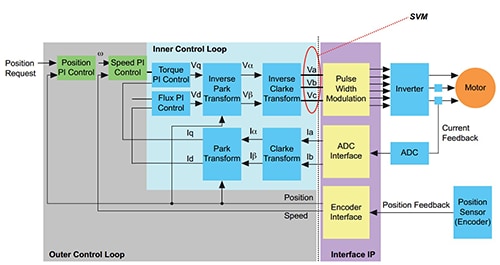
- What level of control algorithm sophistication and complexity do you need, and how much I/O? For example, FOC demands multiple, concurrent calculations involving complex transformations and thus advanced functional blocks (Figure 6).
- Figure 6: An advanced motor-control approach such as field-oriented control requires multiple numerical transforms and both a fast inner loop and a slower outer loop. (Source: Altera)
- If using a general-purpose programmable IC or FPGA, who provides the control algorithms and code: the IC vendor, a third party partnering with them, or an unrelated third party? How are they verified and tested for your motor and application?
- If using a dedicated, pre-programmed control IC, does it offer the range of functions and features needed?
- How much user-programmability do you need or want? Even dedicated, non-programmable controllers allow users to select algorithm type, closed-loop control mode (position, velocity, acceleration), and set operating parameters such as time constants or allowable error band.
- Will there be a need to adjust or modify the basic algorithm, or do the motor and application have unique attributes? If so, a programmable IC might be better. On the contrary, is there a concern that there will be constant requests to modify the algorithm? In this case, a dedicated IC with hard-wired embedded algorithms may be better than a fully programmable one.
- Does the controller have to support one motor type or multiple types? Even if just one type, is it one motor size of that type, or a range of sizes?
- To what level does the vendor provide technical support? What is their actual, hands-on motor experience? Do they provide detailed reference designs that have been built and tested, including the interface between the control IC and MOSFET drivers?
- Are there regulatory issues to be aware of, such as mandated efficiency (many motor applications must now meet various "green" standards)? If so, does the vendor understand and meet them, in their components and algorithms?
Chip and Board Examples Show Controller, Interface Capabilities
For many engineers, pulling all the parts together - the controller with embedded or separate algorithms, the drivers, and the MOSFETs - is a multidisciplinary task, and one for which they don't want to "reinvent the wheel." For this reason, many vendors of motor-control ICs provide evaluation boards and even complete shippable boards that include controller, algorithms, drivers, and MOSFETs.
For example, the 1240i from Applied Motion Products is a programmable step-motor driver, suitable for a wide range of motion-control applications (Figure 7). It includes a sophisticated controller integrated with a 50-watt microstepping amplifier and connects directly to the stepper motor, providing programmable motor current of up to 1.2 amps/phase and speeds to 50 rev/sec.
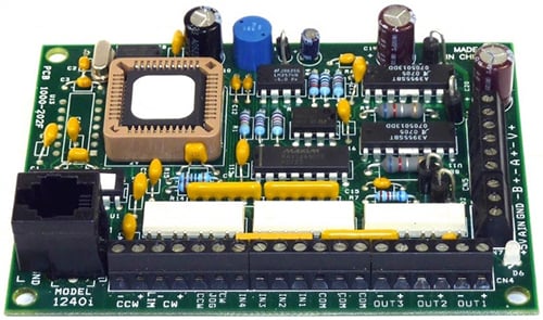
Figure 7: The 1240i Programmable Step-Motor Driver from Applied Motion Products is a complete motion-control package, and can be directed from a PC in the end application, or used as a self-contained, standalone controller after setup. (Source: Applied Motion Products)
Different variations are available to handle the many standard stepper versions and interfaces in use. The board can be programmed by user via the vendor's motion control toolkit and a standard PC to be a standalone motion controller. It can also be commanded in real time from a host PC or programmable logic controller (PLC).
Robotics has an exciting future ahead. Sensing, control, and motors are key areas where innovation will continue to shape how robots evolve as innovation in technology continues to unfold.
Sidebar: Go with Fluid Power?
Using compressed fluids is an alternative to electric motors for robotic motion. This can take two forms: oil-based hydraulics and air-based pneumatics. Hydraulic-based power has a long history in applications that need significant amounts of power, such as earth-moving equipment, and was used in early auto-assembly-line robotics because it was well understood, with a long history. However, a hydraulic actuator needs careful integration of the electronic-control functions with the hydraulic design and components, as well as a compressor/pump in addition to the electrical-power supply. Further, the inevitable problems of seals leaking, complexities of maintenance (electrical and hydraulic technicians are needed), and the environmental consequences of leaks and spills make it a choice only when there is no viable alternative, or when sensitivity to electrical noise (EMI/RFI) is a concern.
Some lower-power applications use compressed air, especially if EMI/RFI and ESD are concerns. Air-based systems do not have the potential problems of hydraulic fluid, but they cannot provide as much power in a given volume, so the supply lines needed for the compressed air are relatively bulky. Like hydraulic-based motion, pneumatic systems can leak, are hard to troubleshoot, and require multidisciplinary knowledge to design, install, and maintain. They can be a viable option for basic, rapid, back-and-forth motion, however.
Due to the dramatic improvements in high-power electric motors and their controls, many applications that previously used hydraulics have switched over, unless there are otherwise compelling technical reasons to stay with hydraulics. For new designs, especially in small-to-medium robotic situations (and even many of the larger ones), the first choice is to go with electronic controls and electric motors. This does not mean that hydraulic systems are obsolete, as there is a need for hydraulics and pneumatics for high-rate, high-impact, high-power bursts. Examples are the ram of metal forging stations (hydraulic) and the launch catapult for aircraft carriers (steam and air).