Programmable Versus Fixed-Function Controllers: Alternatives for Complex Robotic Motion
By Bill Schweber for Mouser Electronics
Control of today's sophisticated robot arms, regardless of their size or power, often requires simultaneous management along multiple axes for their motion control. Modern electronics–the motors, power-switching devices (Metal-Oxide Semiconductor Field-Effect Transistors [MOSFETs] or Insulated-Gate Bipolar Transistors [IGBTs]), device drivers, control systems (now digital, formerly all analog), and feedback sensors–now make achieving precise motion control easier than it was just a few years ago (Figure 1). At the same time, however, the demands on system performance have increased dramatically, so the overall project is as difficult as ever.

Figure 1: A basic motion-control system for robotics includes algorithm-execution functions, motor drivers, power devices, and a feedback path; mechanical linkages, motor, and sensor (in most cases); and voltage and current measurement and control at key points. (Source: National Instruments)
Nonetheless, there's one unavoidable fact: Robotics is largely a mechanical function, so the realities of such systems must be part of the control loop. These include gear backlash, mechanical tolerances, vibration, motor performance, rotating mass inertia, momentum, flexing of mechanical structures, variable loads, and more. For these reasons, it is important to decide what type of motor is the best fit—usually the choice is between brushless DC motors and stepper motors in low/moderate power situations.
Another necessary decision is related to sensor-based feedback. Most robotic applications use some type of feedback sensor to accurately gauge the end-effector's position, and thus velocity and acceleration (recall that velocity is the time integral of position, and acceleration is the time integral of velocity). This feedback transducer can be a Hall-effect sensor, a synchro/resolver, or an optical encoder. While it is easiest to put the encoder on the motor, placing it there may not provide required data about the end-effector's actual situation, with sufficient accuracy for the application, due to mechanical issues noted above. Therefore, the sensor may need to be mounted closer to the load endpoint.
Some motion-control applications operate without a sensor, which reduces cost and mechanical complexity. Rather than using a sensor for feedback, Sensorless Field-Oriented Control (FOC, also called vector control) uses precise, synchronized readings of the current and voltage at each phase of the motor windings; FOCs then perform complicated frame-of-reference transformations and matrix calculations in real time to determine the motor's position. Eliminating the sensor reduces hardware cost, but it necessitates significant computational capability and more complex programming. Many robotic designs still prefer to use sensors because FOC does not provide the same level of confidence, credibility, and robustness that using direct-sensor readout offers.
Understanding Basic Robotic Configurations
While the general public may associate the term "robot" with a mobile, life-like servant or assistant, most robotic systems in the industrial domain are stationary and use a variety of mechanical arms and configurations to perform tasks. Among the most common arrangements are:
-
The Cartesian robot, which has three linear axes of motion, one each in the x, y, and z-planes (Figure 2). This setup is used in pick and place machines, application of sealant, and basic assembly.

Figure 2: The Cartesian robot is the easiest to comprehend and control because it has the simplest equations and works in the x, y, and z planes. (Source: RobotPark)
-
In a cylindrical robot, all motion is confined to a cylinder-shaped zone. It combines linear motion in the y plane, linear motion in the z plane, and rotational motion around the z-axis (Figure 3). This robotic arrangement is used for assembly, tool handling, and spot welding.

Figure 3: The cylindrical robot has motion along two linear axes and around one rotational axis. (Source: RobotPark)
-
The spherical or polar robot combines two rotary joints and one linear joint, and the arm is connected to the base with a twisting joint (Figure 4). Motion is defined by a polar coordinates system and confined to a spherical zone. They are found in welding, casting, and tool-handling applications.

Figure 4: The spherical or polar robot combines motion around two rotary axes and along one linear axis, and it requires numerous calculation-intensive transformations between coordinate frames of reference. (Source: RobotPark)
The approaches cited here offer three degrees of freedom, using a combination of linear and rotary motion; however, some applications need only one or two degrees. More advanced robotic arms or articulated robots combine additional linear and rotary motion, for almost human-like dexterity and flexibility (Figure 5). Some leading edge arms provide six, eight, or even more degrees of freedom.

Figure 5: The articulated robot arm combines multiple rotation and linear motion modes for many degrees of freedom, but it also requires careful coordination among the actuators and arms. (Source: RobotPark)
Other designs use special combinations of linear and rotary motion for application-specific situations, such as the parallelogram implementation; an implementation used for precise and rapid motion over short distances, for example, pick and place of tiny components. As the number of degrees of freedom increases, achieving rapid, smooth, accurate, and synchronized control along each of these degrees grows exponentially more challenging.
Considering Trajectory Profiles
The motion-control objective in robotics seems simple enough: Have the end-effector optimally reach its target position as quickly and accurately as possible with the supported load. Of course, there are tradeoffs involved, as in all engineering decisions, depending on the priorities associated with the optimum result in the given application.
For example, is it acceptable to accelerate and decelerate more quickly to more rapidly reach a higher velocity if the result is overshot and if there is even possible oscillation at the end point? Is it worth trading accuracy for speed, and to what extent? How are the choices of acceleration, velocity, and position related to the desired transition from position A to position B? What are the priorities and parameters that define "optimum" in a particular application?
Specialists in motion control for robotics and other motion applications have developed standard trajectory profiles that provide various ways to implement the desired tradeoff solution for a given application. All choices involve significant real-time calculation based on the present situation and feedback signal, but some impose a more substantial, high-resolution computation burden. These profiles include:
-
The simple trapezoid, where the motor accelerates at a fixed rate from zero to a target velocity, stays at that velocity, and then ramps down at a fixed rate to zero velocity at the desired position (Figure 6). Higher rates might speed up the entire positioning cycle, but they might also induce sudden changes in acceleration motion, called the jerk, which, in turn, adds to inaccuracy and overshoot.

Figure 6: The simplest motion-trajectory profile is the trapezoid, which has constant acceleration to the target velocity, constant path velocity, and constant deceleration between start and endpoints. (Source: Performance Motion Devices)
-
The S-curve, a frequently-used enhancement to the trapezoid, where the acceleration rate ramps up from zero, then decreases as the target velocity is achieved (Figure 7). Then, as the target position is reached, the deceleration rate is ramped up and then reduced as the endpoint is near. The S-curve actually has seven distinct phases, in contrast to the three phases of the trapezoid.

Figure 7: The S-curve path is more complicated than the basic trapezoid, but it eases the jerk (change in acceleration) at each transition point of the path. (Source: Performance Motion Devices)
-
In contoured motion, the user establishes a set of desired positions, and the motion controller directs a smooth, jerk-free transition profile through all of these points (Figure 8). This allows the ultimate in flexibility and control, which is necessary for advanced motion situations. The required calculations of control directions to achieve smooth curve-fitting are complex and must be accomplished without loss of resolution due to rounding or truncation errors, despite the many calculations.

Figure 8: The contoured-motion path allows the user to define a series of position marker points between starting and ending points, and the controller must guide the end-effector through these in a smooth curve. (Source: National Instruments)
There are other profiles in use, some of which are associated with specific application groups or industries. Regardless of the desired profile, it's one thing to want it and another to make it happen. The well-known, highly effective Proportional-Integral-Derivative (PID) closed-loop control algorithm is the most common approach used to drive the motor and end-effector to do what is wanted with high enough accuracy and precision (Reference 1).
Effective control of a single axis is a manageable project, but robotic control becomes far more difficult when this control extends to two, three, or more motors and degrees of freedom, which must be closely coordinated and synchronized with the performance along one dependent on the status of the others.
Determining Standard Versus Custom Motion Control Applications
For standard motion control applications, a dedicated, fixed-function, embedded controller Integrated Circuit (IC) offers ease of use and rapid time-to-market. In contrast, if a non-standard, customized profile is needed or if the correlation between the various axes is complicated and must accommodate unusual or unique events, then the design team may consider a fully user-programmable processor. This solution is implemented with a processor with Digital Signal Processor (DSP) capabilities for the computation-intensive aspects or with a Field-Programmable Gate Array (FPGA). When considering programmable devices, the vendor, third-party tools, and available software modules are factors in making a specific selection, in addition to the hardware functions of the IC itself.
Note that these controllers are generally not the same as motor drivers, which are the MOSFET/IGBT drivers/devices that control motor power, for two reasons. First, these power devices must be sized to the motor, independent of the controller. Second, the high-density complementary metal-oxide-semiconductor-based process technologies used for these digital controllers are very different than the processes for power devices. For smaller motors, however, it is possible to integrate the controller with the driver and power device. Despite the fundamental differences, the term "controller" often refers to the power-device functional blocks, which can lead to confusion in keyword searches.
Some examples of motion control ICs show the spectrum that these devices span. At the basic single-function end, the Toshiba TB6560AFTG is a Pulse Width Modulation (PWM) chopper-type stepping motor controller and driver IC designed for sinusoidal-input microstep control of bipolar stepping motors (Figure 9). Housed in a 48-lead Quad Flat No-leads (QFN) package measuring just 7 × 7 mm, it provides high-performance forward and reverse driving of a two-phase bipolar stepping motor using only a clock signal, and it can deliver up to 2.5A to the motor windings.
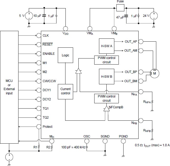
Figure 9: The Toshiba TB6560AFTG is a stepping motor controller with microstepping capability that also includes 2.5A power MOSFETs for direct drive of the motor coils. (Source: Toshiba Corporation)
One of the issues with stepper motors, even when used in microstepping mode, is that their output motion can vibrate as they start or stop their step motion. While not a problem in many situations, it can be a concern in the handling of delicate objects like glassware, or if it induces system resonances. Therefore, the TB6560AFTG allows the user to tailor the rise/fall of the current drive and establish rise and fall transitions for this current to minimize vibration (Figure 10).
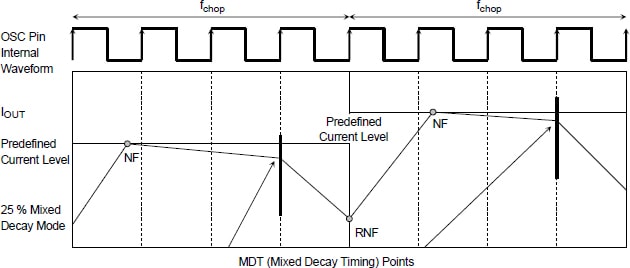
Figure 10: In application, the Toshiba TB6560AFTG requires only a few external components and is guided by high-level directives from a system processor, which it translates into detailed stepping control signals. (Source: Toshiba Corporation)
At the top end of the robotic motion-control pyramid are advanced units such as those in the Texas Instruments C2000 microcontroller families. C2000 represents multiple broad families of devices with various combinations of basic processing, numeric capabilities, types and number of input/output, and housekeeping functions like timers, watchdogs, and pulse width modulation generators.
For example, processors in the TMS320 Delfino series under the C2000 umbrella (Figure 11) offer native floating-point support to eliminate the challenge of fixed-point development, and they also support porting code between fixed- and floating-point native devices with the IQMath™ virtual floating-point engine. This eliminates the need for a second processor with a single or dual core that is efficient at both the Digital Signal Processing (DSP) math tasks and microcontroller system-control tasks. They also include a Trigonometric Math Unit (TMU) accelerator, which expedites trigonometric-based algorithms common in many control-loop calculations such as torque loops.
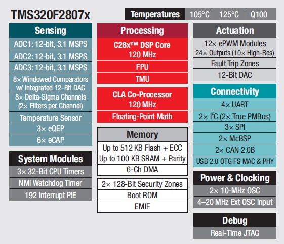
Figure 11: The C2000 family from Texas Instruments consists of several subfamilies, each in turn with many members; the Delfino group includes a powerful processor and embedded coprocessors plus many hardware-based internal support functions to reduce programming load and speed execution. (Source: Texas Instruments)
Supporting this processor are development tools and kits such as the LAUNCHXL-F28377S C2000 Delfino LaunchPad, which is based on a TMS320C28x 32Bit CPU core (Figure 12). The LaunchPad features a F28377S microcontroller unit (MCU) which provides 400 MIPS of total system performance between a 200MHz C28x central processing unit and a 200MHz real-time control co-processor. This microcontroller contains 1MB of on-board flash and includes highly differentiated peripherals such as 16bit/12bit analog-to-digital converters, comparators, 12bit digital-to-analog converters, delta-sigma sinc filters, high-resolution pulse-width modulators, enhanced capture modules, enhanced quadrature-encoder pulse modules, Controller Area Network (CAN) modules, and much more.
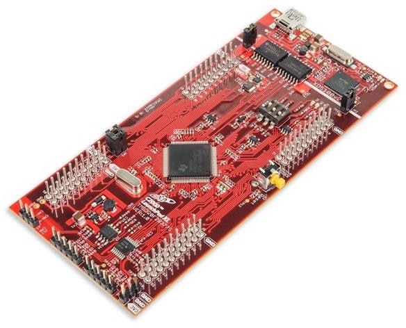
Figure 12: Tools such as the LaunchPad from Texas Instruments are critical for developing, integrating, and evaluating the advanced hardware and software of applications that C2000 Delfino-class processors target. (Source: Texas Instruments)
In addition to the MCU, the LauchPad has a built-in isolated XDS100v2 JTAG Emulator, which enables real-time in-system programming and debugging via USB. The LaunchPad also includes dual 40-pin headers to support two BoosterPacks simultaneously; includes a free, unrestricted version of Code Composer Studio (CCS) Integrated Development Environment (IDE); and adds a free download of controlSUITE™ software.
Conclusion
Motion control options for robotics range from basic, dedicated-function ICs to highly integrated, extremely flexible MCUs with a large array of auxiliary processing and support functions. Although embedded devices may seem limiting, some of them allow selection of a variety of motion profiles and setting of critical parameters, and they are quite adequate, have low cost, and are easy to use. For advanced designs with unique or extremely sophisticated requirements, or designs needing additional levels of connectivity along with control, MCUs offer effective solutions with evaluation and development kits supported by verified code packages, debug and code-development tools, and validation suites.
External References
- IEEE GlobalSpec Electronics360, "Proportional Closed-Loop Control: The Foundation of Automated Systems"
- Chuck Lewin, Performance Motion Devices, "Mathematics of Motion Control Profiles"
- National Instruments, "Fundamentals of Motion Control"
- Motion Design, "Motion Profiles"