Enhancing Real-World Applications with Time-of-Flight Sensors

Image Source: PALERM089/Stock.adobe.com
By Joseph Downing, Mouser Electronics
Published November 17, 2023
Time-of-flight (ToF) sensors are a groundbreaking class of technology that has revolutionized many industries by enabling accurate distance measurement. Among the key advantages of ToF sensors are their speed and precision. By measuring the time it takes for light or signals to travel, ToF sensors can determine distances with remarkable accuracy, even in dynamic environments. These sensors have found widespread adoption across a diverse range of real-world applications, offering enhanced capabilities in fields such as robotics, augmented reality, and automotive.
In the automotive industry, ToF sensors play a pivotal role in improving safety features. These sensors are integrated into advanced driver-assistance systems (ADAS) to enable adaptive cruise control, lane-keeping assistance, and collision avoidance systems. By accurately measuring the distance between vehicles and objects on the road, ToF sensors contribute to safer driving experiences and pave the way for the development of autonomous vehicles. As technology continues to evolve, ToF sensors are anticipated to find even more applications, further reshaping the way we interact with the world around us.
This project will provide the reader with a detailed walkthrough of the necessary steps to successfully assemble and program the ams OSRAM TMF8821-Shield Development Board. In addition, the article will provide an overview of each example.
Project Material and Resources
Before beginning this project, make sure you have all of the required products, software, and resources.
Project Bill of Materials (BOM)
- ams OSRAM TMF8821-SHIELD Sensor Development Board
- NXP Semiconductors LPCXpresso55S69 Development Board (LPC55S69-EVK)
Project Code and Software
- LPC55S69 SDK download
- 19.zip
- MCUXpresso IDE (Login for download required)
Additional Resources
- ams OSRAM TMF8821-SHIELD Quick Start Guide
- TMF882X_Driver_User_Guide (Included in the TMF882x_Driver_SDK_Source file)
- TMF882X_Software_Development_Kit_Getting_Started_Guide (Included in the TMF882x_Driver_SDK_Source file)
Additional Hardware
- Micro USB to USB type A (Included)
- Windows-based PC
Project Technology Overview
This project taps into the features of the ams OSRAM TMF8821-SHIELD sensor development board and the NXP Semiconductors LPCXpresso55S69 development board.
ams OSRAM TMF882X-SHIELD Sensor Development Board
The ams OSRAM TMF8821-SHIELD sensor development board (Figure 1) presents a versatile solution tailored for the evaluation of the TMF8821 multi-zone direct time-of-flight (dToF) sensor. This development platform is designed in the familiar Arduino UNO form factor, making it conducive for rapid assessment of the TMF8821's capabilities.
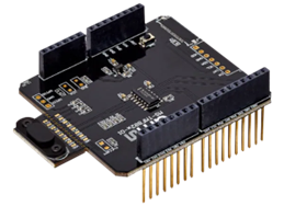
Figure 1: ams OSRAM TMF8821-SHIELD sensor development board. (Source: Mouser Electronics)
At its core, this platform is equipped with the TMF8821 sensor, conveniently mounted on a separate breakaway board. This design feature facilitates the seamless integration of the sensor into prototype hardware arrangements. Measuring a mere 20mm × 12mm, the compact dimensions of the sensor’s breakaway board offer flexibility in various application scenarios.
The following are the key features of the TMF8821-SHIELD:
- Arduino UNO form factor
- TMF8821 sensor securely mounted on a breakaway board
- Inclusive assortment of cover glass samples, with thickness options ranging from 0.5mm to 0.8mm
- Array of air gap spacer samples, available in thicknesses of 0.17mm, 0.25mm, 0.38mm, and 0.5mm
- Convenient breakaway board Vdd current sense test point
- Incorporation of a reset button for enhanced usability
- Onboard low-dropout (LDO) voltage regulator and I²C level shifter, further augmenting the platform's functionality.
NXP LPCXpresso55S69 Development Board
The NXP Semiconductors LPCXpresso55S69 development board (LPC55S69-EVK) (Figure 2) is a specialized platform tailored for the evaluation and development of the LPC55S6x microcontroller unit (MCU) based on Arm® Cortex®-M33 architecture. This development board is fully integrated with the MCUXpresso suite of tools, delivering an extensive set of resources for streamlined development. The MCUXpresso suite encompasses device drivers, middleware, rapid development capabilities, configuration tools, and even an optional integrated development environment (IDE) available at no cost.
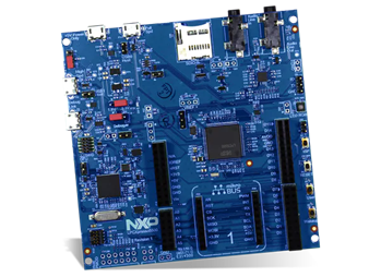
Figure 2: NXP Semiconductors LPCXpresso55S69 development board. (Source: Mouser Electronics)
The LPCXpresso55S69 development board is a comprehensive and versatile toolset designed to empower developers in harnessing the capabilities of the LPC55S6x MCU, facilitating efficient evaluation and development processes within the Arm Cortex-M33 framework.
The following are the key features of the LPCXpresso55S69 development board:
- LPC55S69 dual-core Arm Cortex-M33 MCU operating at speeds of up to 100MHz
- Onboard high-speed USB connectivity with Link2 debug probe featuring CMSIS-DAP and SEGGER J-Link protocol options
- UART and SPI port bridging capabilities from the LPC55S69 target to USB through the onboard debug probe
- Hardware support for an external debug probe
- Three user LEDs, reset button, three ISP buttons, and user buttons for enhanced control
- Equipped with a 4-bit SDIO microSD card slot for expanded storage options
- Integrated NXP MMA8652FCR1 accelerometer for motion sensing
- Stereo audio codec with line in/out functionality
- High-speed and full-speed USB ports featuring a micro-A/B connector, suitable for both host and device applications
- Mikroe Click board™ expansion option for added versatility
- LPCXpresso-V3 expansion site compatibility with Arduino UNO
- Digilent Pmod™-compatible expansion/host connector to accommodate various expansion modules
Developing the Project
The project is very straightforward in both the assembly as well as the software.
Hardware Setup
No tools are required to set up the hardware. Line up the TFM882x shield with the Arduino headers on the NXP LPC55S69-EVK and gently seat the board as shown in Figure 3.
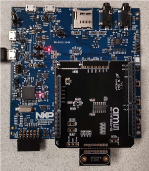
Figure 3: Connecting the ams OSRAM TMF882X-SHIELD to the NXP LPC55S69-EVK development board. (Source: ams OSRAM)
Software Setup
This guide will direct you through each step to successfully set up everything needed to run any of the provided examples in the ams OSRAM software development kit (SDK).
Downloads and Installations
Three downloads are required for this project: ams OSRAM Software Development Kit, NXP MCUXpresso IDE, and MCUXpresso SDK.
ams OSRAM Software Development Kit
Download the ams OSRAM SDK developed to run on the NXP LPC55S69-EVK. Using the link provided in the Project Code and Software section download the TMF882X_Driver_SDK_Source_vX.XX.zip, making sure to download the latest revision. This project uses v1.19, which is linked in the Resources section (Figure 4).
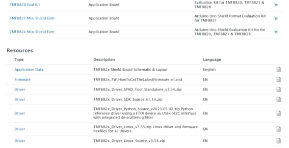
Figure 4: TMF882x Driver SDK download from the ams OSRAM site. (Source: Mouser Electronics)
Once downloaded, extract the files, and locate the Software Development Kit Getting Started Guide located in the document folder of the extracted files.
MCUXpresso IDE
Download and install the latest version of the NXP MCUXpresso IDE (linked in the Project Material and Resources section), which we will use as the interface to the NXP board (Figure 5).
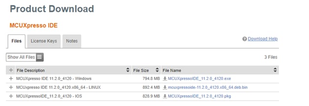
Figure 5: MCUXpresso IDE download page. (Source: Mouser Electronics)
Once downloaded, execute the installation, and follow all on-screen instructions to complete the installation, including installation of device drivers or controllers (Figure 6).
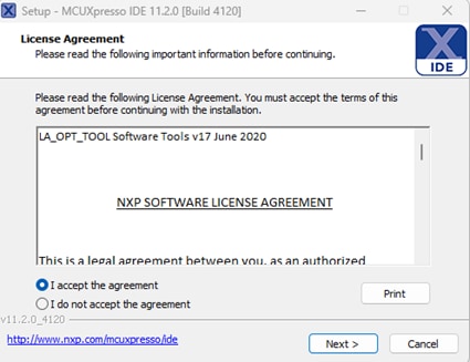
Figure 6: MCUXpresso installation window. (Source: Mouser Electronics)
MCUXpresso SDK
Once the IDE is installed, install the MCUXpresso SDK. If you are launching the IDE for the first time, the option to download and install the SDK will be available in the Welcome tab (Figure 7).
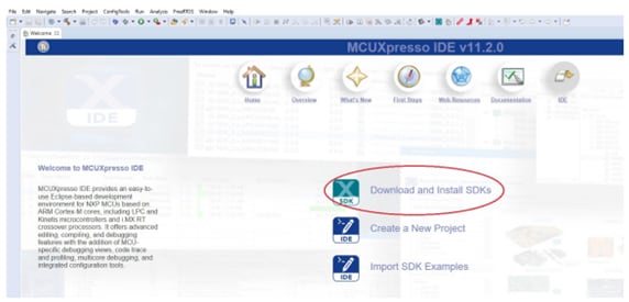
Figure 7: MCUXpresso IDE SDK installation welcome screen. (Source: Mouser Electronics)
Alternatively, you can install the SDK by clicking the blue X icon in the task bar of the MCUXpresso IDE (Figure 8).

Figure 8: MCUXpresso SDK new install window icon. (Source: Mouser Electronics)
A window will appear, showing a list of boards (Figure 9). In the Filter search bar in the top right of the window, type “lpcxpresso55s69” and click install from the list of boards, making sure to select only the most current revision if more than one option is available. Follow all on-screen instructions for the installation. Once completed, restart the MCUXpresso IDE by selecting File and then clicking Restart.
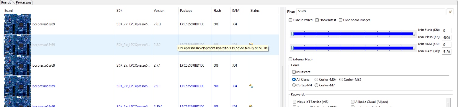
Figure 9: MCUXpresso SDK search and selection. (Source: Mouser Electronics)
If everything has installed correctly, you will be able to see successfully installed SDKs in the Installed SDK window (Figure 10).
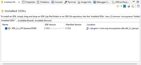
Figure 10: Installed SDKs window. (Source: Mouser Electronics)
Putting It All Together
With all the necessary software installed, we will now begin programming and running the provided examples.
Programming the Hardware
Using the micro-USB cable, plug the USB-A side into the programming PC and the micro-USB side into the USB connector labeled Debug Link on the left side of the board as shown in Figure 11.
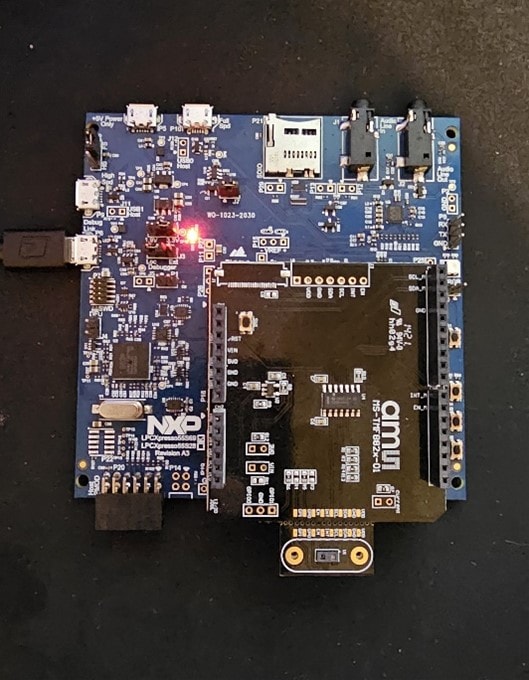
Figure 11: Assembled hardware with USB cable plugged in for programming. (Source: Mouser Electronics)
Next, import the example project for this demonstration.
- Open the MCUXpresso IDE.
- Click File, and then click Import….
- From the Import window, click General and select Existing Projects into Workspace.
- Select the Select root directory radio button, click Browse…, and navigate to the extracted ams OSRAM Software Development Kit.
- Highlight the TMF882X_example_simple folder and then click Select Folder (Figure 12).
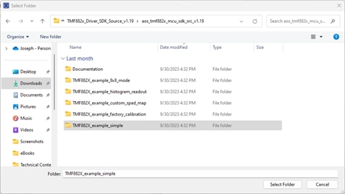
Figure 12: Selecting the example program for import. (Source: Mouser Electronics)
- On the Import window, in the Projects section, select the checkbox to the left of the example program (Figure 13).
- Select the Copy projects into workspace
- Click Finish once complete.
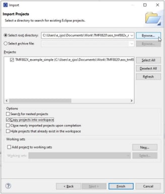
Figure 13: Importing project options. (Source: NXP)
Once you have loaded the project and connected the board, build and run the project.
- In the MCUXpresso IDE, click Project and then click Build All.
- Verify that the build has finished without error from the console window (Figure 14).
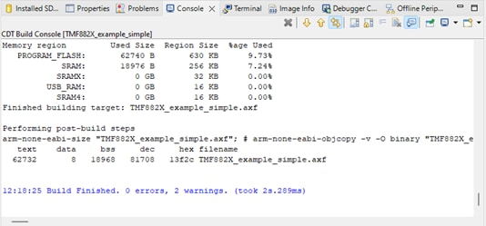
Figure 14: Console window showing finished program build. (Source: Mouser Electronics)
To run the application, click the Debug button (Figure 15). This will open the Debug Configurations window.

Figure 15: Debug button. (Source: NXP)
In the Debug Configurations window, select TMF882X_example_simple Link Server Debug, and then click Debug at the bottom right of the window (Figure 16).
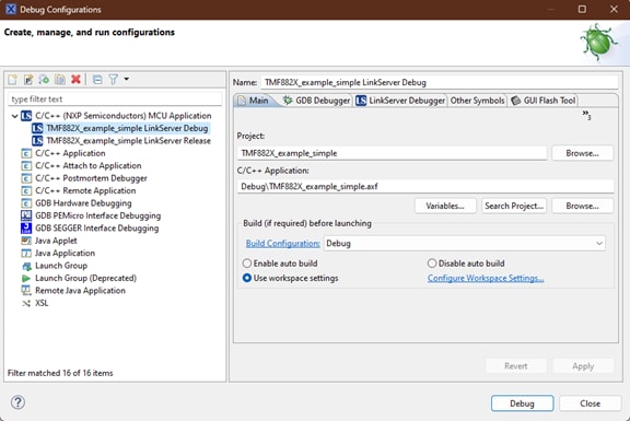
Figure 16: Debug Configurations window. (Source: Mouser Electronics)
A window will open to verify that the connection has been made between the LPCXpresso55S69 and the programming PC. If not checked, select the checkbox next to the MCUXpresso IDE LinkServer in the Supported Probes section of the window (Figure 17) then click OK.
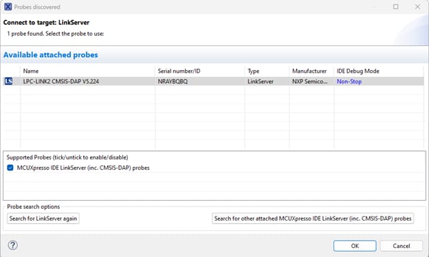
Figure 17: LinkServer connection window. (Source: Mouser Electronics)
The debugger program will launch and program the device. Next, launch a terminal window:
- From the Terminal window, select the Open a Terminal icon (Figure 18).
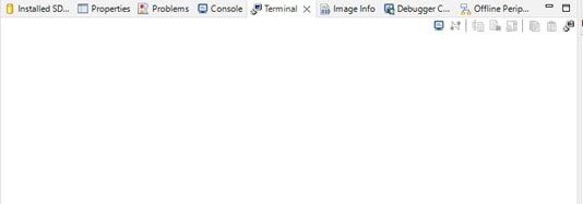
Figure 18: Terminal window. (Source: Mouser Electronics)
- From the dropdown menu, select Serial Terminal, and then click OK.
- Make sure the serial port settings are as shown, changing the serial port to match the devices (Figure 19), and then click OK.
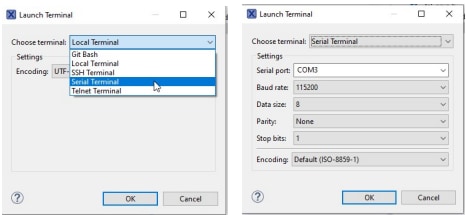
Figure 19: Terminal settings. (Source: NXP)
- Click the green Resume icon to resume the application from the break point (Figure 20).

Figure 20: Debug Resume button. (Source: NXP)
Once done, you will be told to press the ISP button on the board to start measurements. A green LED will illuminate while running and measurements will be displayed in the terminal window (Figure 21). To stop, simply terminate the debug session by click the square red Terminate button just right of the Resume icon.
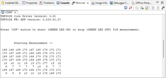
Figure 21: ToF simple example serial output. (Source: Mouser Electronics)
This example provides a basic demonstration with minimal configurations and illustrates a very simple use case. The example measures and prints the results in centimeters using a default 3×3 zone. Pressing the ISP button on the NXP board will begin the measurements, which will be indicated by a green LED illuminating.
Additional examples in the software folder provide a deeper look at device capabilities such as factory calibration and configuring an 8×8 zone.
Conclusion
Time-of-flight (ToF) sensors offer remarkable speed and precision in distance measurement, even in complex environments. The ams OSRAM TMF8821-Shield Development Board in conjunction with the NXP Semiconductors LPCXpresso55S69 Development Board, can provide engineers with an effective and efficient way to develop products in industries ranging from robotics to automotive, empowering them to further explore the capabilities of ToF sensors.