How to Add a Machine Learning Access Control

Image Source: BeeBright/Shutterstock.com
By Michael Parks for Mouser Electronics
Published May 27, 2021
Introduction
The past few years have seen a rapid evolution in machine-learning (ML) technologies. What once required the computational horsepower of a beefy desktop computer can now be done comfortably on portable, battery-operated hardware. Inferencing, the phase of the ML workflow in which real-world data is fed to a pre-trained neural network model, can be performed in a highly efficient manner thanks to the combination of improved algorithms and new, dedicated hardware.
Keyword spotting —think “Alexa, what time is it?” —is one such family of problems that ML algorithms are quite adept at solving with relative ease (meaning not requiring significant computer horsepower in terms of memory or processor speed). To highlight just what is possible with machine learning and embedded systems, we’ve devised a proof-of-concept for a voice-controlled access control device. First, a user will have to scan an radio-frequency identification (RFID) tag then speak a four-digit access code. Do that correctly and a motor will activate, granting access to whatever you secrets you wish to stash.
For the embedded hardware, this project will leverage the Maxim Integrated MAX78000 evaluation kit (Figure 1), powered by an Arm® Cortex®-M4 processor. The MAX78000 also contains a hardware-based convolutional neural network (CNN) accelerator. The MAX78000 empowers small, portable devices with the capability of handling ML inferencing algorithms while sipping only microjoules of energy. MAX78000 also contains user-definable pushbuttons, TFT display, and a digital microphone that we will leverage for this project.
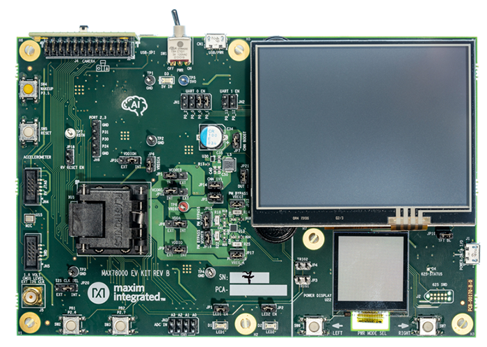
Figure 1: Maxim Integrated's MAX78000 Evaluation Kit. (Source: Maxim Integrated)
In addition, we will use a PN532 RFID tag reader to add two-factor authentication to the project. The project will also incorporate a Trinamic TMC5130A motor controller (Figure 2) and a stepper motor to provide a physical interaction with the real-world, specifically simulating a lock mechanism. Both the RFID reader and motor controller will be offloaded to an Arduino Nano, which in turn will interface with the MAX78000 EVKIT.
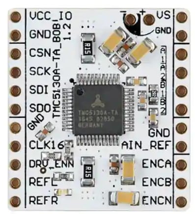
Figure 2: Trinamic's TMC5130A Motor Controller Breakout Board. (Source: Trinamic)
Bill of Material (BOM)
You can click this Mouser project share link to access the bill of materials (BOM) along with the current pricing. Table 1 lists the items in the BOM.
Table 1: Machine Learning Access Control Project Bill of Materials
|
Quantity |
Mouser P/N |
Description |
|
1 |
700-MAX78000EVKIT |
Development Boards & Kits - ARM MAX78000 EVALUATION BOARD |
|
1 |
700-TMC5130A-BOB |
Power Management IC Development Tools Breakout board for TMC5130A-LA |
|
1 |
485-324 |
Stepper Motor |
|
1 |
485-364 |
RFID Reader |
|
1 |
782-ABX00033 |
Arduino Nano Every with Headers |
|
1 |
563-BB-32621 |
Breadboard |
|
1 |
854-ZW-MM-10 |
Jumper Wires |
Resources
All source files for this project are located on Mouser's GitHub Repository. The repository is divided into two main folders including:
Documentation
The Documentation> folder contains graphic files of schematics and other important reference materials.
Software
The Software> folder contains the source code, grouped into major folders:
MAX7800EVKIT:Contains the source code that runs the convolution neural network, listens for the keywords via the onboard microphone, and drives the TFT display.Arduino Uno:Contains the source code to manage the PN532 RFID tag reader and the TMC5130A motor controller.
More details about these source code files can be found in the Software section below.
Tools
This project assumes that you have access to the following tools:
- Windows 10-based computer with a high-speed Internet connection
- Digital Multimeter
- Soldering Iron
- 12VDC Power Supply
Building the Project
In this section, we will examine the necessary steps to get your project up and running. The section is broken down into the following subsections:
- Hardware Setup
- Setting up the Software Development Toolchain
- Software Development
- Project in Action
Figure 3 is the project’s wiring diagram.
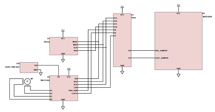
Figure 3: Wiring diagram for the project components. (Source: Mouser)
Hardware Setup
The hardware setup for this project will require a small amount soldering of through hole components. A digital multimeter is also recommended in order to verify continuity and to ensure proper voltages. First, let’s begin with the Arduino Nano.
Arduino Nano
- Solder the headers to the circuit board, if needed.
- Place the Nano on the breadboard so that the micro-USB connector faces to the edge of the breadboard.
TMC5130A Breakout Board
- Solder female headers to each side of the TMC5130A breakout board.
- Wire the TMC5130A to the Arduino Nano as follows:
- SDI to MOSI (D11)
- SDO to MISO (D12)
- SCK to SCK (D13)
- CSN to SS (D7)
- GND to GND
- 5V to 5V
- DRV_ENN to D9
- CLK16 to D8
- Connect TMC5130A to a 12VDC power supply
- VS to the positive terminal of the power supply
- GND to the negative terminal of the power supply
- Wire the stepper motor to the TMC5130A as follows:
- Red wire to A1
- Blue wire to A2
- Green wire to B1
- Black wire to B2
NOTE: The color of the wires for your particular stepper motor can vary. Check the documentation to ensure phase A and phase B winding are connected correctly.
PN532 RFID Reader
- Solder the headers to the PN532 circuit board, if needed.
- Wire the PN532 to the Arduino Nano as follows:
- MOSI to MOSI (D11)
- MISO to MISO (D12)
- SCK to SCK (D13)
- NSS to SS (D10)
- GND to GND
- 5V to 5V
NOTE: The language used by many communications protocols is evolving. Serial Peripheral Interface (SPI) is one such protocol. MISO (Master In Slave Out), MOSI (Master Out Slave In), and SS (Slave Select) have given way to SDO (Serial Data Out), SDI (Serial Data In) and CS (Chip Select) for single-role hardware. MISO and MOSI has also been replaced by CIPO (Controller In, Peripheral Out) and COPI (Controller Out, Peripheral In) when connected devices can serve in either role. You will likely encounter both the new and old phraseology for some time. Be sure to check all component documentation to ensure wiring connections are made correctly.
MAX78000 EVKIT Board
- Connect the Arduino Nano GND pin to the GND pin of the MAX78000 EVKIT Board.
- Connect the Arduino Nano pin D6 to PB2 jumper on the MAX78000 EVKIT Board.
- Connect the Arduino Nano pin D5 to the LED1 jumper on the MAX78000 EVKIT Board.
Setting up the Software Development Toolchain
To develop the MAX78000 firmware for this project, we will be using the Maxim Micros SDK (Figure 4) based upon the Eclipse Software Development Kit (SDK). The software requires a Windows 10 computer and is a free download here. For the Arduino Nano portion of the project, we will be using the Arduino IDE, available for free from here.
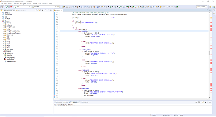
Figure 4: The Maxim Micros SDK, based on Eclipse development environment. (Source: Maxim Integrated)
To program the MAX78000 EVKIT, the following connections need to be made between the development board and a Windows 10-based computer:
- Plug a micro-USB cable into the micro-USB port labeled USB PWR along the top of the MAX78000 EVKIT.
- Plug a ribbon cable into the MAX32625 PICO programming adapter.
- Plug the opposite end of the ribbon cable into the SWD port (JH4) onboard the MAX78000 EVKIT development board.
- Plug a micro-USB cable into the MAX32625 PICO programming adapter.
- Plug the opposite ends of both USB cables into a computer.
- Toggle the power switch (labeled PWR) along the top of the MAX78000 EVKIT development board from the OFF position to the ON position.
Although the MAX78000 firmware contains all the needed libraries in a self-contained project, it will be necessary to add external libraries to control the PN532 RFID reader and the TMC5130A stepper motor controller. The first library, the PN532 library, can be found in the native Library Manager (Figure 5) of the Arduino IDE. This can be accessed from the toolbar, simply navigate Sketch > Include Library > Manager Libraries. Then search for the keyword PN532. Select the PN532 library from the search results and then click Install.
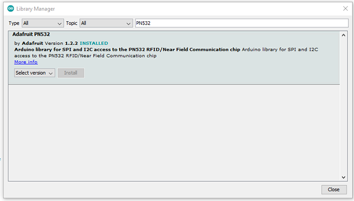
Figure 5: Adding third-party software libraries via the Library Manager. (Source: Green Shoe Garage)
The second library required to command the stepper motor controller must be downloaded and installed manually. First, ensure you have Git installed on your computer and then open a command prompt (Figure 6). Issue the following command:
>git clone https://github.com/mikest/Estee_TMC5130
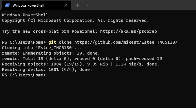
Figure 6: Installing the TMC5130A library via Git. (Source: Green Shoe Garage)
Next, use a Zip utility to create a .zip file containing the entire Estee_TMC5130 folder. Next, from within the Arduino IDE navigate to Sketch > Include Library > Add .ZIP Library. Select the recently created Estee_TMC5130.zip file and click OK.
Software Development
The codebase for this project is written in C. It consists of two major components. First is the firmware that runs on the MAX78000 and controls the ML inferencing, drives the TFT display, and listens for keywords using the microphone. The second is the firmware that runs on the Arduino to control the PN532 RFID reader and TMC5130A motor controller.
Key Files
cMAX78000/main.c: Contains the core functionality of the user-facing features. This includes handling the microphone input, driving the TFT display, and logic that drives detection of the correct spoken passcode.cMAX78000/cnn.candcnn.h: Contains the ML model, optimized for MAX78000 hardware, to detect the various spoken keywords.cNano_FW/ ino: This file contains the main logic to handle the RFID reader and the motor controller.cNano_FW/TMC5130_registers.h: Contains the various device register addresses for the TMC5130A. Knowing the correct addresses allows the development to interact with and control the stepper motor.
Key Variables and Constants
You might want to tweak a few variables depending on your particular design choices. These variables and can be found in MAX78000/main.c:
static enum { LOCKED, THREE_MORE, TWO_MORE, ONE_MORE, UNLOCKED } state = LOCKED;
The state enumerated data type institutes a very simple state machine that allows the device to track the status of the device. It begins in a LOCKED state, then once the first digit of the passcode is spoken it progresses to the next state. This continues for each subsequent passcode digit until all four have been spoken correctly. The last state is the UNLOCKED state. Once the device enters this state, the motor is triggered.
const char keywords[NUM_OUTPUTS][10] = { "UP", "DOWN", "LEFT", "RIGHT", "STOP", "GO", "YES", "NO", "ON", "OFF", "ONE", "TWO", "THREE", "FOUR", "FIVE", "SIX", "SEVEN", "EIGHT", "NINE", "ZERO", "Unknown"};
This array contains the text of the various keywords the CNN has been trained to detect. Each keyword is assigned an integer as an index into the array. Table 2 outlines the relationship between the keyword and index value.
Table 2: Spoken Keyword to Array Index Crosswalk
|
KEYWORD |
INDEX |
KEYWORD |
INDEX |
|
UP |
0 |
ONE |
10 |
|
DOWN |
1 |
TWO |
11 |
|
LEFT |
2 |
THREE |
12 |
|
RIGHT |
3 |
FOUR |
13 |
|
STOP |
4 |
FIVE |
14 |
|
GO |
5 |
SIX |
15 |
|
YES |
6 |
SEVEN |
16 |
|
NO |
7 |
EIGHT |
17 |
|
ON |
8 |
NINE |
18 |
|
OFF |
9 |
ZERO |
19 |
|
UNKNOWN |
20 |
These following variables are found in the file named MAX78000_AccessControl_NanoFW.ino and can be edited to suit your specific components and project requirements.
uint32_t approved_rfid_tag = 2165834:This is the identification number that is associated with the RFID tag. This will need to be modified for your particular RFID tag.
Setting a Custom Passcode
To set a custom passcode, a switch statement is located in the MAX78000/main.c file. To alter the passcode (the default is set to 1-2-3-4), the first four switch cases must be altered (Figure 7).
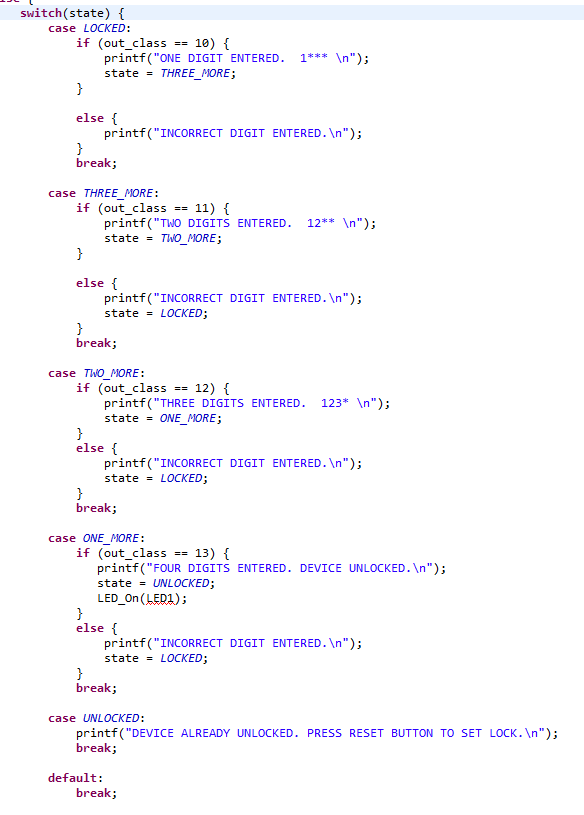
Figure 7: The original code that defines how the spoken passcode is detected. (Source: Green Shoe Garage)
Let’s look at what it takes to change the first digit of the passcode from a ”1” to a “9”. Look at the case labeled LOCKED (case LOCKED:). It contains an if statement which compares a variable named out_class to an integer value. That integer value is related to the values found in Table 2. The variable out_class is set by the machine-learning algorithm based on which spoken keyword was probably spoken by the user. Looking in Table 2, we see that the spoken keyword “1” is assigned an index value of 10. Furthermore, the spoken keyword “9” is assigned to index value 18. So to change the pin from “1-2-3-4” to “9-2-3-4”, the out_class value that the if statement checks for in the LOCKED case must be changed from 10 to 18. The revised code appears in Figure 8.
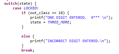
Figure 8: Changing the pin from 1-2-3-4 to 9-2-3-4 revises the code. (Source: Green Shoe Garage)
Project in Action
The program flow is as follows:
- User swipes an RFID tag across the PN532 RFID reader.
- RFID tag information is transmitted to the Arduino Nano via SPI.
- The RFID tag information is compared to an authorized RFID tags.
- If an authorized a tag is detected, the MAX78000 is triggered to begin listening for the spoken, four-digit passcode.
- Wait for LED2 to turn RED.
- Once the passcode is spoken correctly, the MAX78000 sends a signal back to the Arduino Nano. For this project, we will be using the super-secret passcode of “1-2-3-4”.
- The Nano communicates to the TMC5130A, via SPI, to engage the stepper motor.
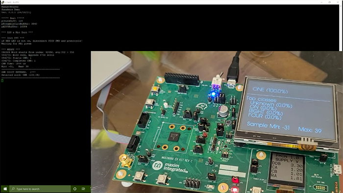
Figure 9: Project in action; command line window with active board.