Honey, I Shrunk the Capacity
Image Source: Adobe Stock/VK Studio
By Ralf Higgelke for TDK Electronics
When selecting a capacitor for a specific application, it’s essential to consider more than just the capacitance and voltage. Other important features include temperature stability, equivalent series inductance (ESL), and equivalent series resistance (ESR). If you just skim through a datasheet, you might not spot this, but it could greatly impact how your system performs. Let’s take multilayer ceramic capacitors (MLCCs) as an example.
Pitfall DC Bias Effect
The capacitance shrinks when you apply DC voltage to MLCCs with a ferroelectric Class II dielectric based on barium titanate. This is also known as the DC bias effect, and the same thing happens when the temperature changes. For example, for an operating voltage of 400V, the actual capacitance of a 630V component drops by around 70 percent of its nominal value because of the DC bias effect. So, in this scenario, a 220nF ceramic capacitor with Class II dielectric turns into one with only 63.8nF (Figure 1). This is a key fact for many designs, and it’s made worse when the temperature changes.
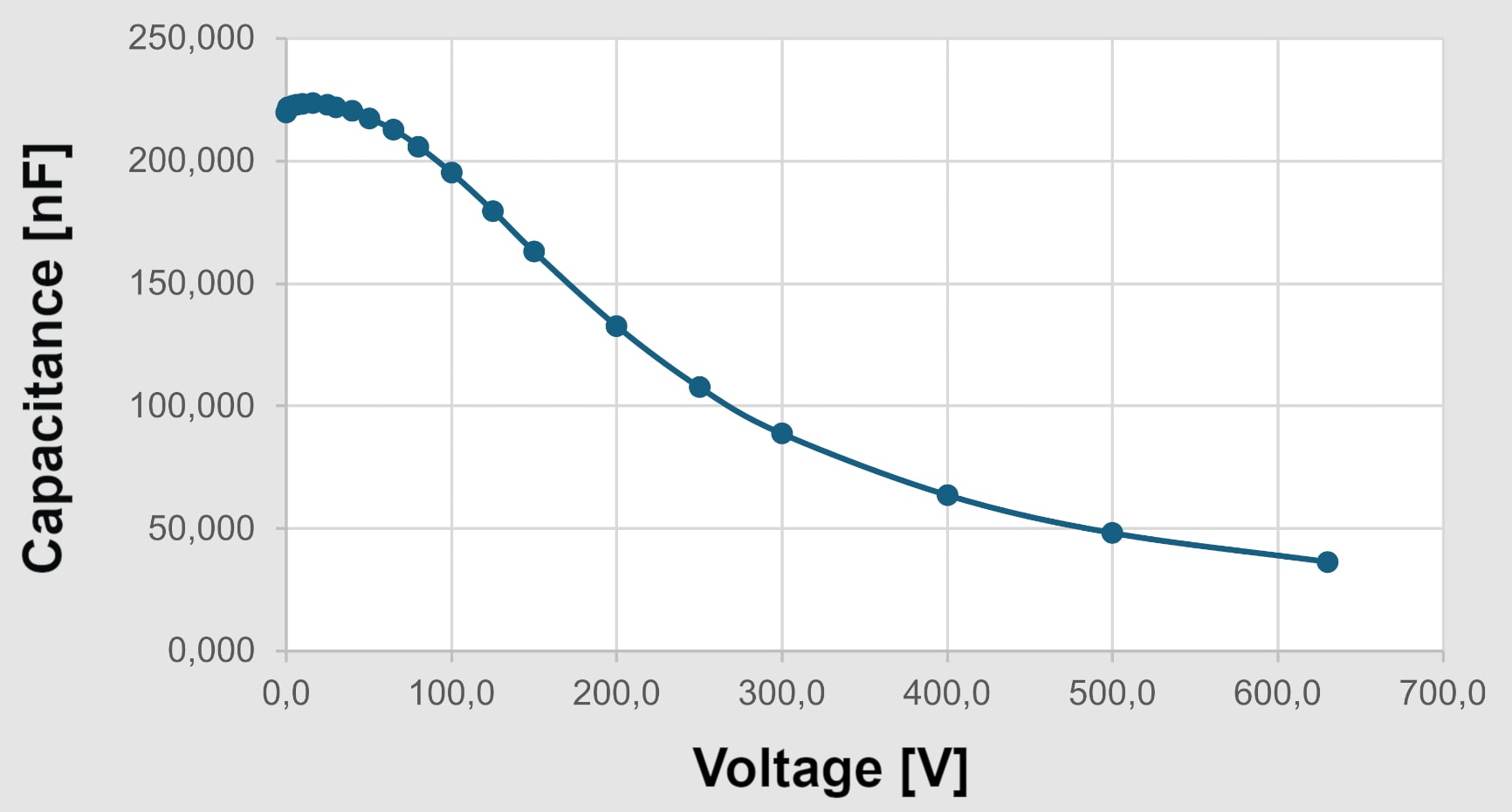
Figure 1: The capacitance of an MLCC with a class II dielectric drops over the operating voltage. (Source: TDK)
Ceramic capacitors based on an anti-ferroelectric dielectric, such as lead lanthanum zirconium titanate (PLZT), differ from MLCCs with a class II dielectric. As shown in Figure 2, the capacitance goes up with the applied DC bias voltage and the AC ripple, but it also depends on the operating temperature. The red line indicates how the capacitance changes with a very low AC ripple, while the black line shows how the component behaves when you apply a voltage from 0V to the rated voltage (e.g., snubber application). It’s clear how the ripple affects the capacitance—the higher this value, the higher the capacitance, which is a bonus in power electronic applications.
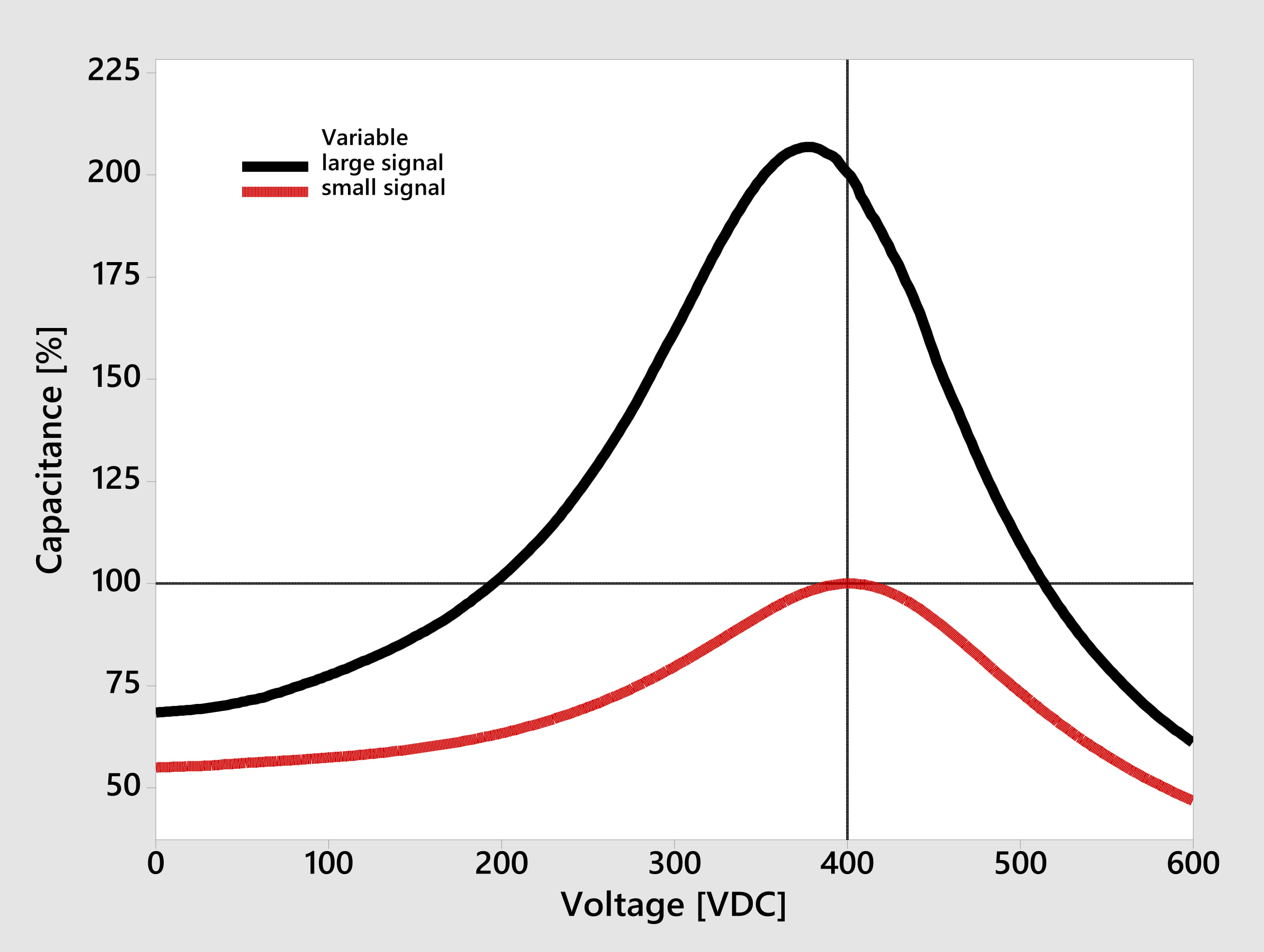
Figure 2: The capacitance of a PLZT-based ceramic capacitor generally increases with the operating voltage. (Source: TDK)
Because of their low ESR at higher frequencies (Figure 3), PLZT-based capacitors are well-suited for use in DC links and snubber applications, or filter circuits in high-voltage, high-temperature applications, such as the power systems of xEVs. There, they can reduce the effects of parasitic inductance.
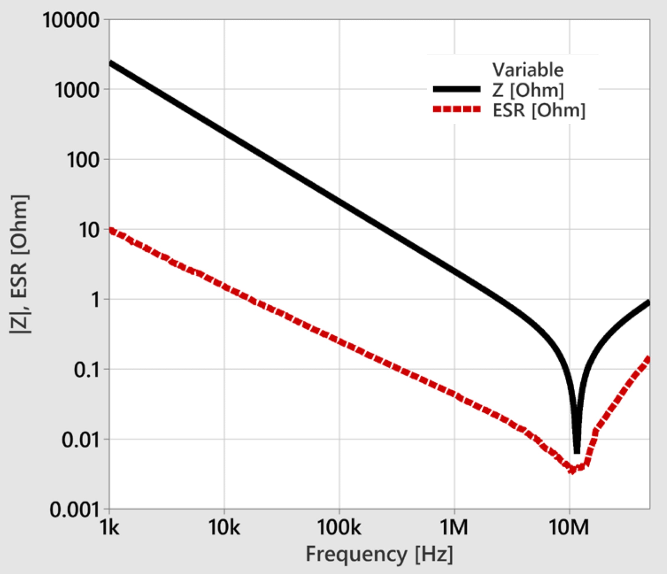
Figure 3: A PLZT-based ceramic capacitor is characterised by a particularly low equivalent series resistance (ESR) at high frequencies. (Source: TDK)
These capacitors can be placed next to a power transistor, which helps ensure the voltage doesn’t overshoot too much and potentially damage the semiconductor. A ceramic capacitor is a super-important part of a snubber circuit, since it stores excess energy from the parasitic inductance when the transistor is switched off. The same goes for the turn-on when the parasitic capacitances of the transistor need to be charged straight away. Placing a ceramic capacitor next to the semiconductor in parallel with the bulk DC link capacitor can provide this instant current. Otherwise, the bulk DC link capacitor must provide this current. That solution has a higher parasitic inductance, which is never good news.
You can only meet high power demands in high-temperature applications like xEV power systems if you add extra cooling measures for bus capacitors. Polypropylene (PP) film capacitors provide the necessary energy density but don’t perform well at high temperatures. This means you must dissipate extra heat to ensure they stay cool enough. However, the CeraLink SMD capacitors from TDK are designed to offer high performance even at high temperatures, so you don’t need to worry about extra cooling.
Converters that use fast-switching semiconductors, such as silicon carbide (SiC) or gallium nitride (GaN), work well with PLZT-based capacitors. The ESR of a capacitor is low, but not negligible, and the constant charging and discharging cause its inside to heat up. As a consequence, the component won’t last as long. However, the ESR of PLZT-based capacitors decreases when the temperature and switching frequency are higher, meaning they can deliver much higher currents in real-world applications.
System Cost Advantage
PLZT-based capacitors cost about twice as much as MLCCs with a class II dielectric. Can they still be a better deal?
Let’s compare the CeraLink B58043E9563M052 (56nF/900V) with MLCCs (both 1000V) with the same 2220 case size in different MLCC solutions, as shown in Table 1. Due to the DC-bias effect, MLCCs with class II dielectric only achieve 12.6nF and 25.9nF, respectively. You’ll need three to four of them in parallel, but a single PLZT-based component will do the job.
Table 1: Comparison of the CeraLink and the MLCC solutions for a snubber application with a requirement of 50nF at 800V. (Prices retrieved from Mouser on 15 January 2025.)
|
|
CeraLink |
Class-II MLCC (1) |
Class-II MLCC (2) |
|---|---|---|---|
|
Rated capacitance CR [nF] |
56 |
120 |
68 |
|
Effective capacitance at 800V [nF] |
56 |
25.9 |
12.6 |
|
Units to get 50 nF at 800 V |
1 |
2 |
4 |
|
1,000-unit price at Mouser [USD] |
0.809 |
1.010 |
0.392 |
|
BOM cost [USD] |
0.809 |
2.020 |
1.568 |
|
Relative BOM cost [%] |
100 |
251 |
224 |
Even though the PLZT-based capacitor costs about twice as much as MLCCs, it’s a better deal for this application at this operating point. Moreover, the cost advantage increases even further when you factor in PCB area and assembly costs. This can save you up to 60 percent of the cost, at least in this example.
The PLZT-based capacitor also has a higher ripple current capability at the component level. It can handle up to 5.0A at 100kHz and +85°C, but the MLCC can only carry 1.17A under the same conditions. So, four MLCCs connected in parallel can handle 4.68A, which is slightly less than the one CeraLink.
Conclusion
PLZT-based ceramic capacitors, like TDK’s CeraLink, are different from regular Class II dielectric capacitors because their capacitance increases with both DC bias voltage and temperature up to the operating point. This unique characteristic makes them a fitting choice for suppressing voltage peaks. Their low ESL supports converters with fast-switching wide-bandgap semiconductors, and their high ripple current capability, due to low ESR at high frequencies and temperatures, shows how versatile they are.
In addition to being useful in a practical sense, CeraLink can also help make your solutions cheaper by reducing or even eliminating the need for thermal management, which means lower system costs and a smaller, lighter final product.
Author
 Ralf Higgelke has more than two decades of experience reporting on power electronics and passive components. Today, he writes and manages most of the technical content for TDK Electronics.