Irrigation Anywhere with Microchip:
IoT Enabled Stepper Motor Control
Image Source: Natali - stock.adobe.com
By Joseph Downing for Mouser Electronics
Introduction
In our previous horticulture projects we’ve provided possible IoT sensor solutions as well as options for IoT lighting control. But what about irrigation? Much like it is for humans, water is essential for plants to flourish and grow. What would it take to create an automated and efficient irrigation system for a greenhouse or vertical indoor farm?
In this project, we will provide directions on how to create an IoT enabled stepper motor that can be controlled via an iOS device such as tablet or phone. Paired with a valve and either a misting/sprinkler system, or soaker hose, you can water your plants from anywhere in the world.
Materials
The material list required for this project is relatively short and includes the Microchip Technology PIC-IoT WG development board, Mikroe Stepper 7 Click board, an adequate power source, bipolar stepper motor, and others listed in the Bill of Materials (BOM).
Project BOM
- Wi-Fi® Development Tools (802.11) PIC-IoT WG
- Power Management IC Development Tools Stepper 7 click
- Switching Power Supplies 36W 15V 2.4A
- Stepper Motors NEMA 14 STEP MOTOR 26AWG 25.53 oz-in
Hardware
- Flat-Tip Screwdriver
- Philips Screwdriver
- Soldering Iron
- Solder
- Flux
- Pigtail NEMA 5-15 Plug
- 26 AWG (or larger) wire
Accounts and Software
- Microchip Technology MPLAB® X Integrated Development Environment (IDE)
- Development Software Medium One cloud environment
- Medium One iOS Application
- Project File located on Mouser Electronics' GitHub site
Overview
PIC-IoT WG
Microchip Technology PIC-IoT WG development board (Figure 1) is an amazing platform for anyone who wants to quickly develop IoT enabled devices. The certified ATWINC15x0 SmartConnect IoT Modules and ATECC608A CryptoAuthentication™ Devices combined with the PIC24FJxxGx 16-bit Microcontrollers creates a simple, secure, and powerful platform for connecting embedded applications to your IoT Cloud Service. The PIC-IoT WG also contains a number of other sensors and power management devices, including:
- MCP9808 Digital Temperature Sensor
- MIC33050 Voltage Regulator
- MCP73871 Battery Charge Management Controller
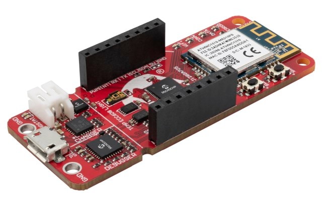
Figure 1: Microchip Technology PIC-IoT WG Development Board (Source: Mouser Electronics)
Mikroe Stepper 7 Click
Mikroe's extensive line of Click Boards™ provides engineers with a quick and effective way of integrating a number of devices into a myriad of different applications. The Stepper 7 Click (Figure 2) is a versatile board, supporting either 3.3V or 5V MCU. By utilizing Microchip Technology MCP23S08 8-Bit I/O Expander over SPI the number of input pins required to control the stepper motor is minimized. Along with the 8-Bit Expander, the Stepper 7 uses the MTS62C19A Dual Full-Bridge Motor Drive, allowing for full, and micro-stepping operations.
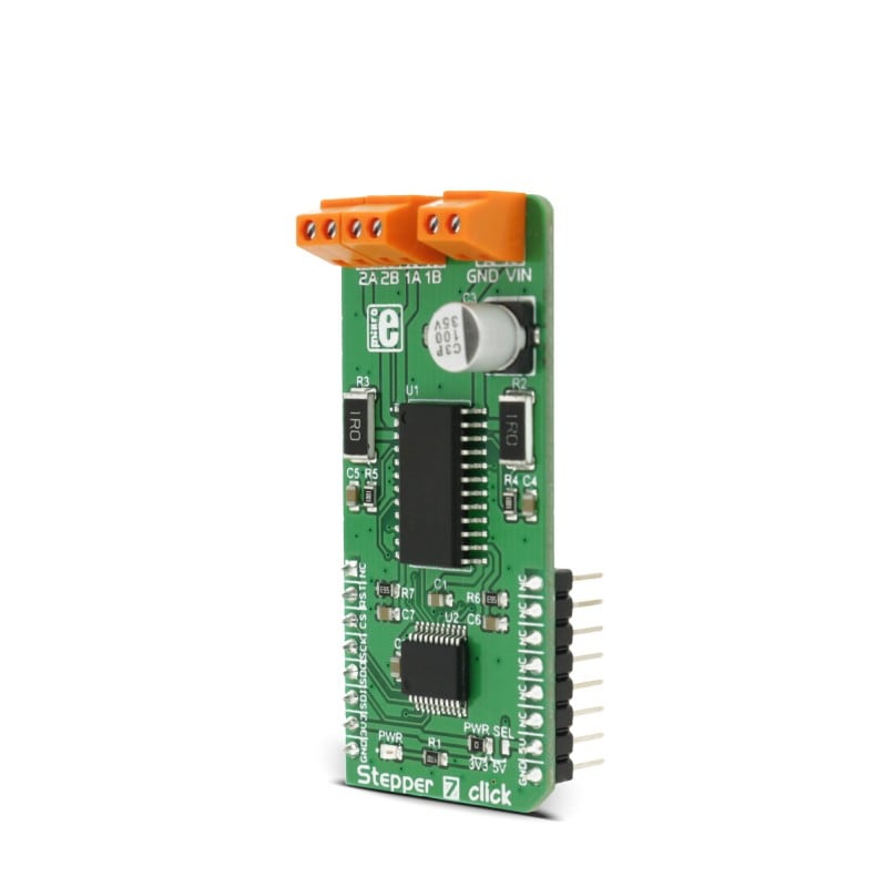
Figure 2: Mikroe Stepper 7 Click Board (Source: Mouser Electronics)
Medium One Cloud Environment
Medium One is a great way to begin an IoT prototype by anyone interested in the early phase development of IoT projects (Figure 3). Highly customizable workflows and prepackaged modules and libraries enable rapid prototyping. Easy to create dashboards allow for quick visualizations and interactions with your data. A low-cost, annual fee with no long-term commitments makes Medium One ideal for anyone ready to jump in and begin developing your own creation.
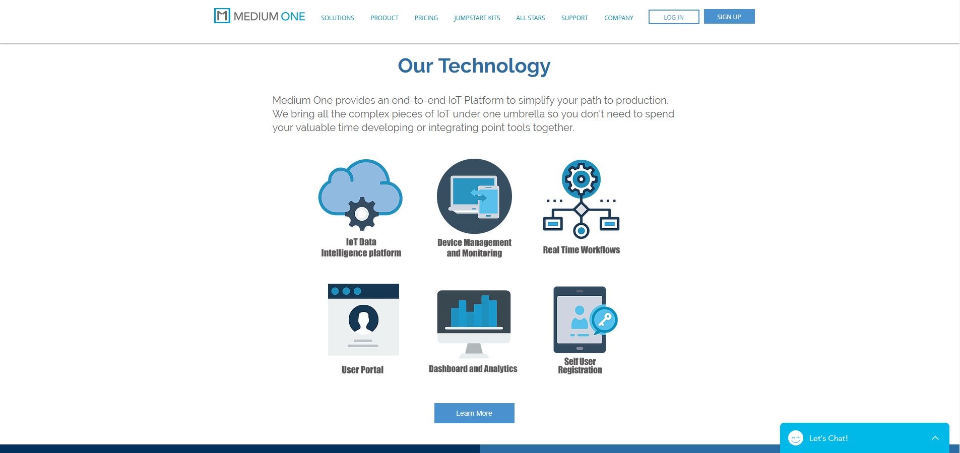
Figure 3: Medium One Sandbox (Source: Mouser Electronics)
Assembling the Hardware
Assembly for this project is pretty straightforward with only a few standouts. Before we start plugging in boards and connecting wires, we will need to make a minor modification to the PIC-IoT WG. Out of the box, the development board is only equipped to provide 3.3V through the onboard headers. However, 5V will be required by the MTS62C19A. In order to get around this you will need to create a solder bridge in the designated spot, identified in the figure below. (Figure 4).
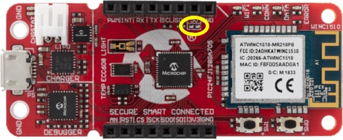
Figure 4: Location for solder bridge necessary to enable 5V through headers (Source: Mouser Electronics)
With that out of the way, complete the following:
- Attach the Stepper 7 Click board to the PIC-IoT WG development platform. Pay close attention to the pin designations in order to assure it is connected correctly.
- Take the stepper motor and, using either a data sheet or DMM to measure continuity, determine which wires belong to each coil.
- Connect each pair of wires from the stepper motor to the set of terminal headers on the Stepper 7 Click board (1A, 1B and 2A,2B) ignoring the polarity for now. (Figure 5)
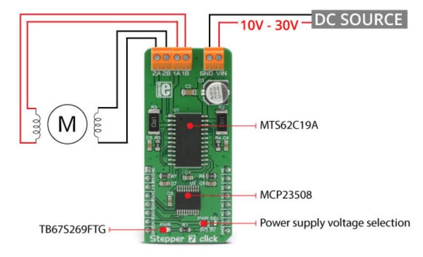
Figure 5: Wiring connections for the Stepper 7 Click board (Source: Mouser Electronics)
- Connect your DC Power source to the GND and VIN header on the Stepper 7 Click board. (Figure 5)
- Connect a micro USB to USB Type A cable from the micro USB connector on the PIC-IoT WG board to an available USB port on your computer
Software and Programming
The project file for the PIC-IoT is stored on the Mouser Electronics GitHub repository. You will need to install the Microchip Technology MPLAB X IDE as well as the MPLAB XC16 Compiler. Follow the instructions onscreen.
Medium One Web Page
Before programming the PIC-IoT WG development board, we’ll need to create our project on Medium One. If you do not already have an account, you will need to purchase the license provided in the BOM and create a new account. Then, do the following:
- Select "Setup" from the left side of the screen and chose "Manage Users"
- Click the "+Add New User" in the lower right side of the screen and set the Login ID and Password for the project (Figure 6)
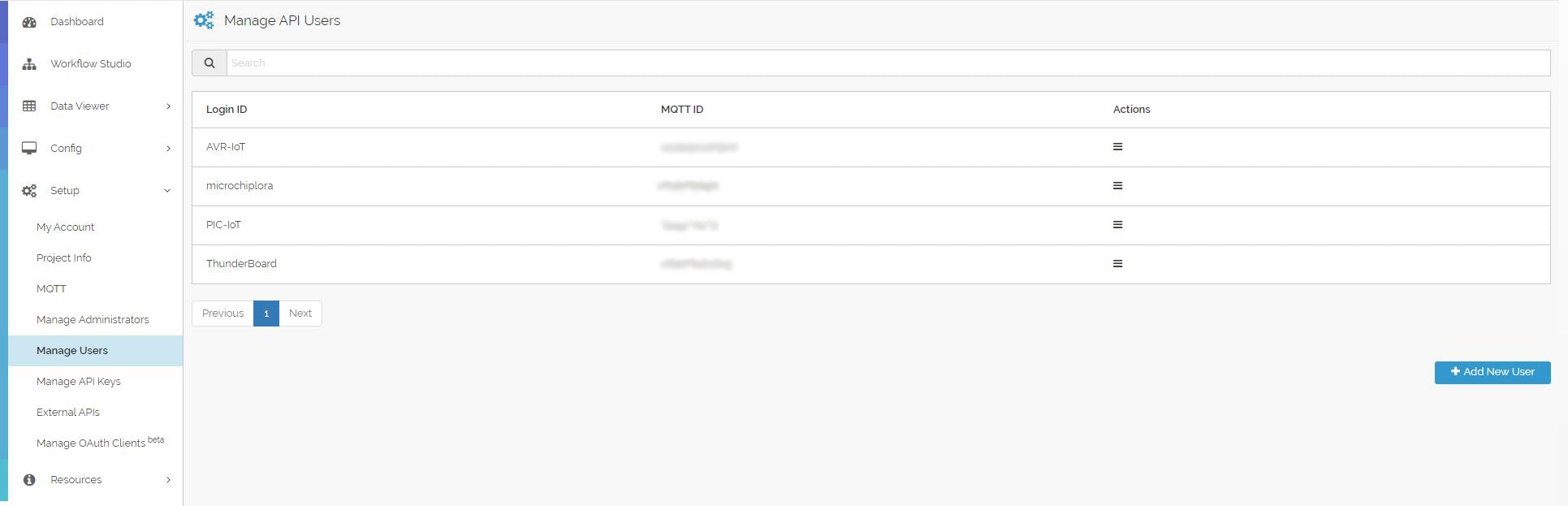
Figure 6: Manage API User Screen (Source: Mouser Electronics)
- Select "MQTT" from the left side of the screen, and take note of the Project MQTT ID (Figure 7)
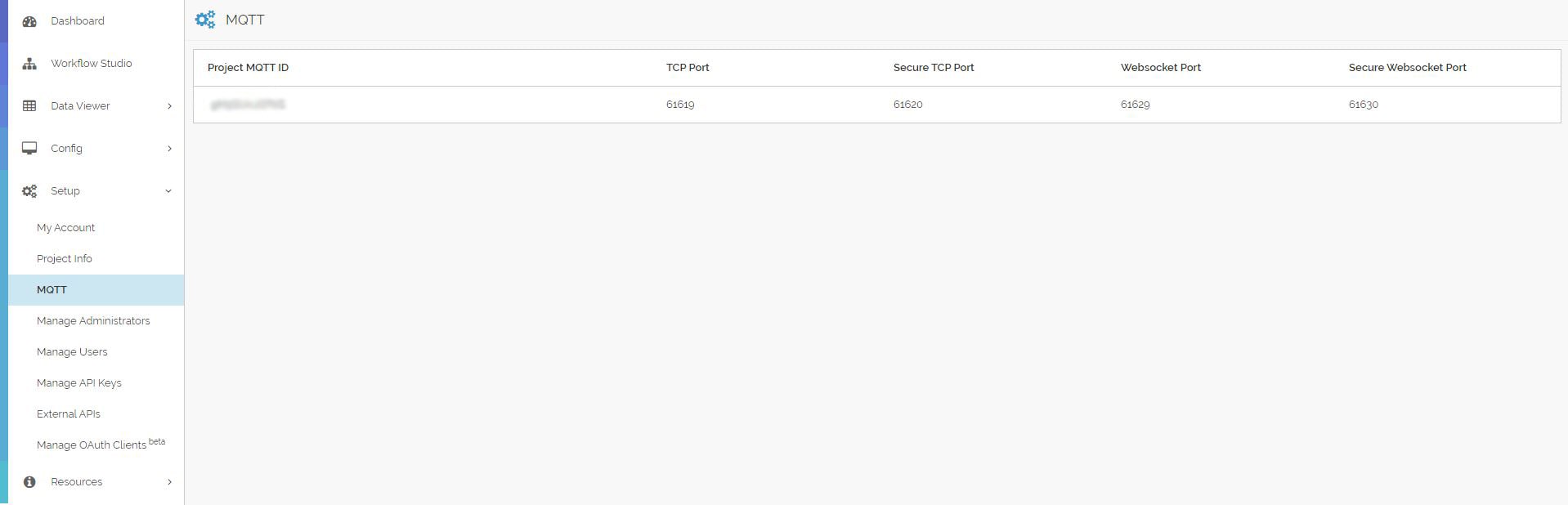
Figure 7: MQTT page with Project MQTT ID (Source: Mouser Electronics)
- Select "Manage API Keys" from the left side of the screen and click the "+Add New API Key" in the bottom right side of the screen. (Figure 8)
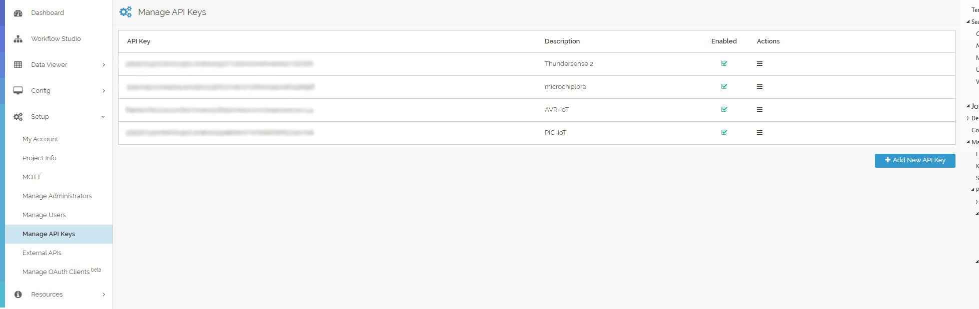
Figure 8: Manage API Keys screen (Source: Mouser Electronics)
The information needed for the login credentials to publish and subscribe to topics is a combination of the information provided and created above. The MQTT Username is created by combining the Project MQTT ID and MQTT ID in the following format: "Project_MQTT_ID/User_MQTT_ID". The MQTT password is created in a similar fashion using the generated API key and user password created in the Manage User screen: "Project_API_Key/Project_Device_Password".
MPLAP X IDE
- Begin by navigating to the Mouser Electronics GitHub repository
- Download and extract the file
HorticultureMotor.zip - Open MPLAB X IDE, select "File" then "Open Project"
- Navigate to the location you extracted
HorticultureMotor.zipand open the project
From here, you will need to update several files in order to proceed. These will allow the device to conncect to your selected wireless network as well as communicate with the Medium One project created in the section above.
- Within the project, locate the file
conf_winc.hunder"Header Files/MCC Generated/config" - Locate the following constants and update them with your WiFi SSID and password (Figure 9)
- CFG_MAIN_WLAN_SSID
- CFG_MAIN_WLAN_AUTH
- CFG_MAIN_WLAN_PSK
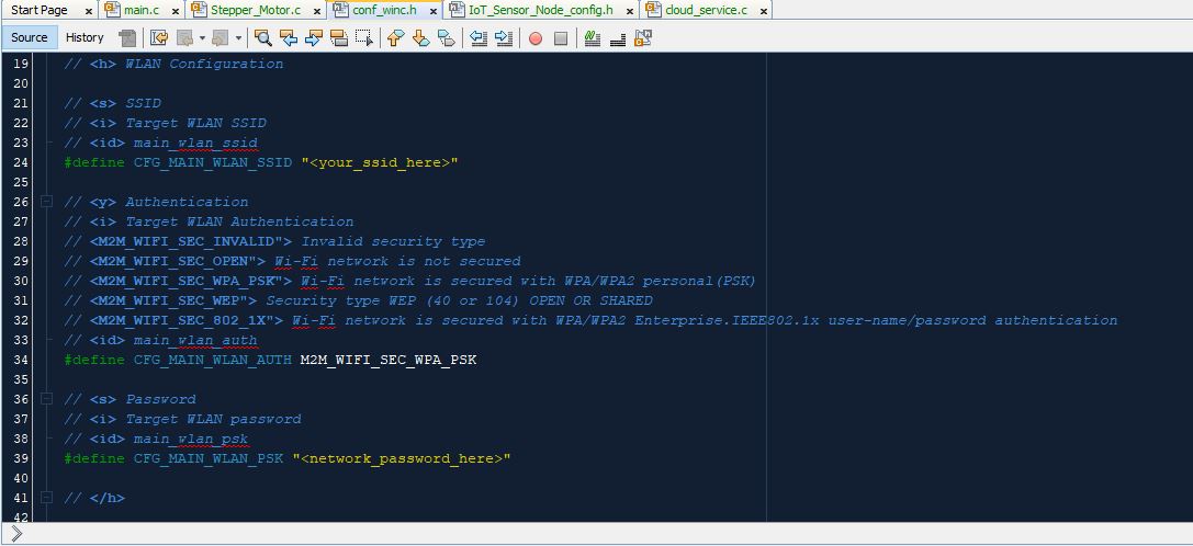
Figure 9: WiFi setup in conf_winc.h (Source: Mouser Electronics)
- Next, open the file
IoT_Sensor_Node_config.hlocated in"Header Files/MCC Generated/config" - Locate the following constants and update them with the MQTT Username and MQTT Password as discussed earlier (Figure 10)
- CFG_MQTT_USERNAME
- CFG_MQTT_PASSWORD
- CFG_MQTT_TOPIC — everything but the Device ID
The MQTT publish topic is formatted in the following way: "0/Project MQTT ID/User MQTT ID/Device ID"
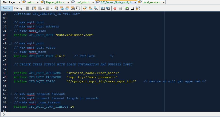
Figure 10: IoT_Sensor_Node_config.h screen (Source: Mouser Electronics)
Next, we need to create our subscribe topic which will allow us to control a device remotely. The subscribe topic is formatted in much the same way the publish topic is: "1/Project MQTT ID/User MQTT ID/Device ID/event"
- Open the file
cloud_service.clocated under "Source Files/MCC Generated/cloud" (Figure 11) - Locate the line
sprintf(mqttSubscribeTopic,
"1/<project_mqtt_id/user_mqtt_id/%s/event", cid); - Update the Project MQTT ID and User MQTT ID
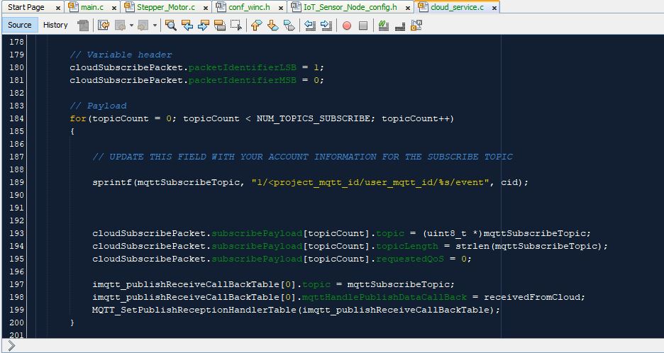
Figure 11: cloud_service file screen (Source: Mouser Electronics)
- Build and program the device
Medium One iOS Applications
Of course, in order to control something remotely, we need to create the controller. For this, we will be using Medium One's iOS Application. After locating and downloading the application, follow these steps:
- Open the application on your device, and add the appropriate API Login information:
- API Key
- User Login
- User Password
- Select "+Add New Widget" from within the device application
- For this project, select "Switch" (Figure 12)
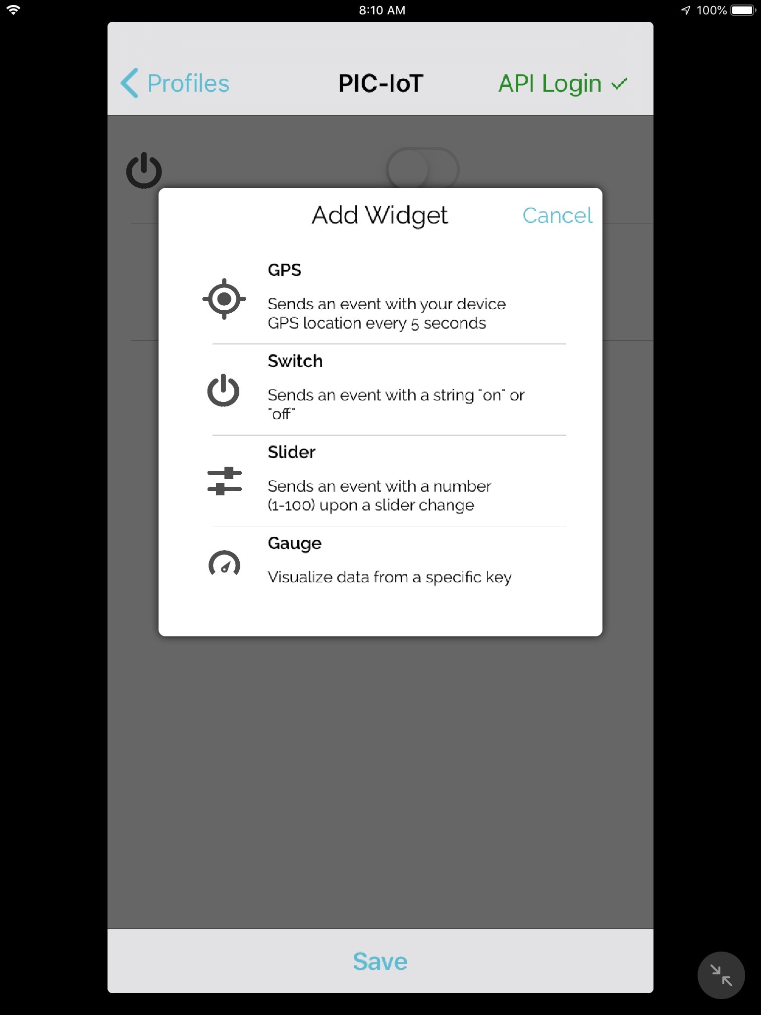
Figure 12: Adding a Widget (Source: Mouser Electronics)
- Click the icon on the left to open the configuration screen
- In the "Stream" field enter "raw"
- In the "Tag" field, enter something appropriate for the project (Figure 13)
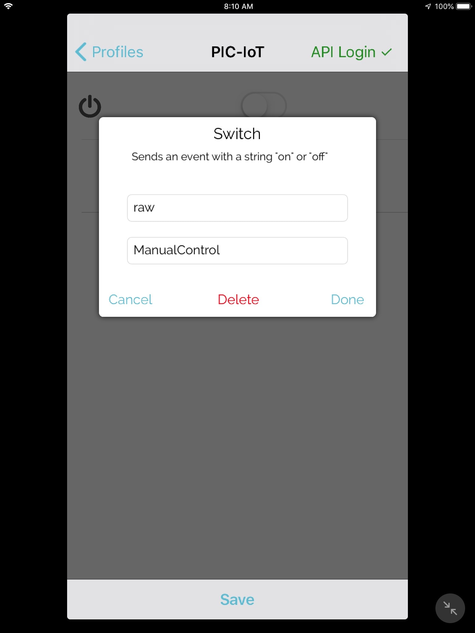
Figure 13: Medium One App, Widget configuration screen (Source: Mouser Electronics)
- Click "Done"
And now we have a button!
Making it Work
If everything is working as it should, the board is currently publishing data from two on-board sensors and looking for any subscribed events. Of course, this does little good without some way of representing the information.
Medium One
- Back in the Medium One web page, select Dashboard from the left
- Locate and select the "Single User Real Time Gauge" from the "Add Widget" section
- From the drop down box, select the user for this project
- Click the cog wheel just to the right of the drop down box and select "raw:light" and "raw:tempc" and click save
This should now provide you with a real-time representation of the PIC-IoT WG onboard sensors. To create the interface between the iOS application and our device, we will first need to create a workflow. These steps will guide you through this:
- On the Medium One web page, select Workflow Studio from the left side of the screen
- Select "Create" and provide a name similar to the one you created in the iOS app
- On the right side of the screen locate the "Tags & Triggers" icon and click it
- Drop down the "raw" tag and locate the one created in the iOS application
- Locate the "Modules" icon along the right side of the screen and select it
- Dropdown the "Foundations" and select "Base Python"
- Double click the "Base Python" block and enter the following code into the script section
import MQTT
mode = IONode.get_input('in1')['event_data']['value']
if (mode == "on"):
MQTT.publish_event_to_client('your_device_id,' 'valve_OPEN',encoding='utf-8')
else:
MQTT.publish_event_to_clietn('your_device_id','valve_CLOSED',encoding='utf-8')
(note: you can find your specific device ID by selecting "Data Viewer" on the left and using the raw Data Stream. Select any of the logs using the ID for your project to display it)
- Select "Save and Activate"
- Lastly, click the circle just below the "Tags & Triggers" box you created and drag a line to the top circle on the "Base Python" box (Figure 14)
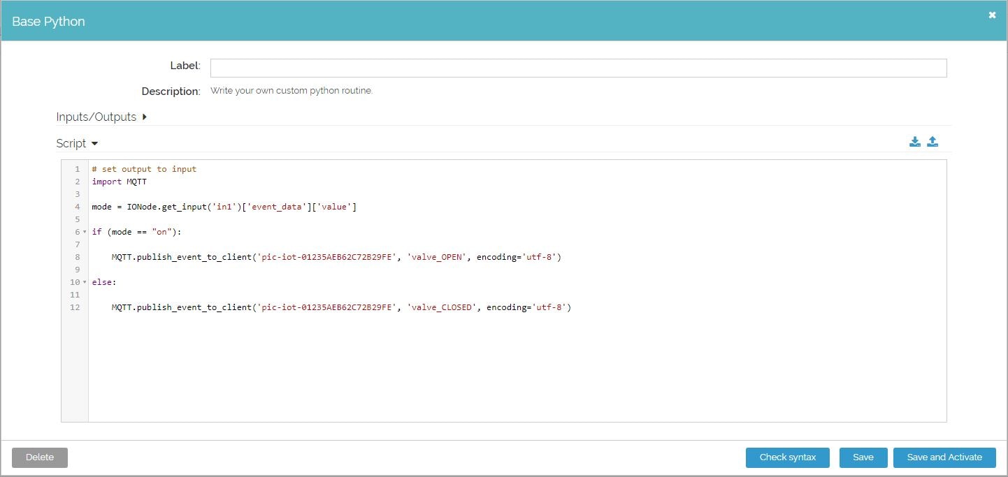
Figure 14: Medium One Workflow Screen (Source: Mouser Electronics)
If your board is plugged in, and a little yellow light is blinking, you should be able to open a terminal window using a program such as Putty or Tera Term to view the output. From here you can see the sensor data being published as well as an update every time you toggle the switch from the iOS application.
Working with the Stepper
Controlling the stepper motor is actually very easy. To see the examples of how this is done, look in the "Stepper_Motor.c" file located in the Source Files folder. (Figure 15)
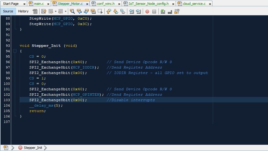
Figure 15: Stepper Motor file in MPLAB X (Source: Mouser Electronics)
You will find several functions including StepperCCW and StepperCW which will allow you to turn the stepper motor one full roation. Writing to the stepper motor requires you to follow three steps:
- Write the device ID code, and set the R/W bit to Write(0). In this case, that is 0x40.
- Send the register address you wish to write to.
- Send the data you intend to write.
To get the stepper motor to actually do something when you flip the switch requires adding something to the main.c file in the "receivedFromCloud" function. Here you can add the code you would want to run every time the switch from the iOS app is toggled. (Figure 16)
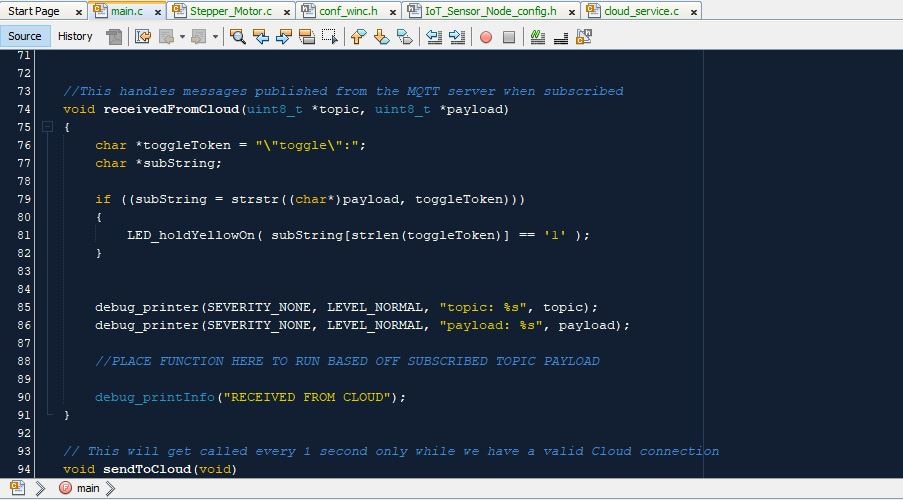
Figure 16: main.c subscribed topic receive function (Source: Mouser Electronics)
In the current iteration of the project, we did not include any code within this function since, depending on the use case, any number of options are available.
Conclusion
This article provides a rudimentary overview of how to control a device such as a stepper motor using a MQTT publish/subscribe method. By itself, you could manually control turning a valve on and off to allow water to flow to your plants, but why stop there? Using the same Workflow Studio in Medium One, paired with the Soil Moisture sensor demonstrated in the article " A Smarter Green Thumb Powered by Microchip," you could create an automated system that would turn on and off as necessary to maintain the moisture level you set. There are countless possibilities available in the horticulture application, as well as many others, limited only by the imagination.
Don't forget to let us know if you tried this project out for yourself. How well did the project work for you? Would you expand upon it? If so, let us know on Facebook®, Twitter, or LinkedIn®