Smarter Machinery with Machine Learning
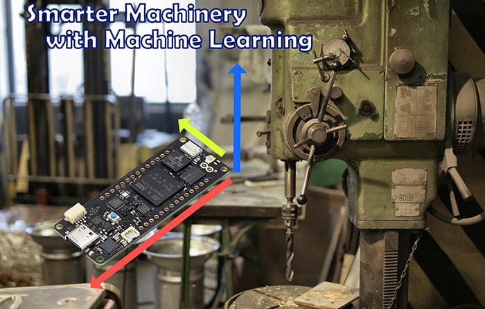
Image Source: Andrea Piacquadio/Pexels
By Michael Parks, PE, for Mouser Electronics
Published February 10, 2022
Introduction
Running a small company specializing in rapid prototyping means investing significant resources in machinery and tooling. Many machines such as computer-numerically controlled (more often referred to as CNC) milling machines can run into tens of thousands of dollars. Some of the most popular machines tend to be older machines whose design is tried and true. While these machines tend to be mechanical workhorses, they often lack some modern features that can make the workflow of a machine operator much more efficient.
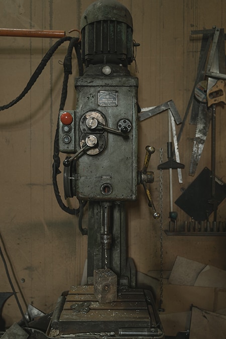
Figure 1: Older machines may lack modern features but tend to be very reliable and finely calibrated. Source: Photo by Tima Miroshnichenko from Pexels
It is not uncommon for a single prototype to require multiple machines spread across a workshop. These machines are far from "set it and forget it" in their operations and maintenance. A single machine operator must be diligent in operating and caring for machines such as CNC mills, lest failure result in lost time at best or expensive repairs at worse. Being able to hire multiple machinists is unlikely if you are a small business. Is there another way to expand the eyes and ears of the machine operator?
Thanks to the emergence of machine learning algorithms, inexpensive hardware with dedicated neural network features, and services that make neural network training a simple matter of a few clicks in the browser, the answer is yes. In this article, we will examine what it takes to retrofit a CNC milling machine with technology to make it self-aware of its "health" and have the ability to communicate its status to a machinist over the Internet.
Project Materials and Resources
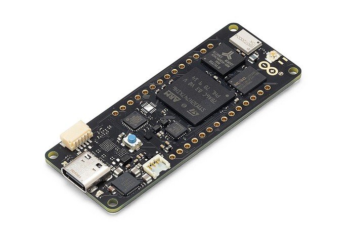
Figure 2: The Arduino Portenta H7 Lite Connected adds Wi-fi and Bluetooth, the industrial-oriented development platform. Source: Arduino
The recently released Arduino Portenta H7 Lite Connected is a powerhouse for those looking for an embedded platform for industrial-grade applications. Like the Portenta H7 Lite, the newer addition to the H7 family also features the dual-core STM32H747 as the main processor. The STM32H747 includes a Cortex M7 running at 480MHz and a Cortex M4 running at 240MHz. This allows the computationally intensive neural network to run on the M7 core. Then low latency code that runs the sensors and wi-fi communications hardware can comfortably operate on the secondary M4 core. What separates the Portenta H7 Lite and the H7 Lite Connected is the addition of wireless communications thanks to the addition of the Murata 1DX module. This module provides 802.11b/g/n Wi-Fi® and BLUETOOTH® 5.1.
To understand the health of the CNC machine, the project will leverage a three-axis accelerometer to constantly read the X, Y, Z-axis of the milling machine. Should it detect motion indicative of a problem (for example, the stepper motors stuttering due to incorrect settings or excess material getting caught in one of the axis rails), then a subroutine will fire off an email notification to the operator.
Bill of Material (BOM)
You can click this Mouser project share link to access the BOM along with the current pricing. As of the date this article was initially written, the BOM cost is about $166 (USD), before applicable taxes and shipping costs. Table 1 lists the items in the BOM.
Table 1: ML CNC Project BOM
Quantity |
Mouser P/N |
Description |
|
1 |
782-ABX00042 |
Arduino Portenta Development Board |
|
1 |
474-SEN-13284 |
LSM9DS1 9DOF Accelerometer Breakout Board |
|
1 |
485-3174 |
Solid Core Hookup Wire |
|
1 |
932-MIKROE-1120 |
Li-Po Battery |
|
1 |
424-6-PIN-HEADER |
Male Header—Single Row |
Resources
All source files for this project are located on Mouser's GitHub repository. The repository is divided into three main folders including:
Documentation
The Documentation folder contains graphic files of schematics and other important reference materials.
3D Files
The 3D Files folder contains .stl files needed to view and 3D print an enclosure that will house the Portenta H7 Lite Connected. The files can be viewed for free at https://viewer.autodesk.com.
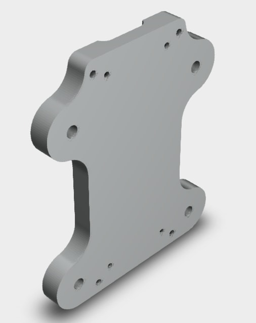
Figure 3: A mounting device for the Portenta. Source: Thingiverse
Software
The Software folder contains the source code, including the following files:
- smartercnc_fw.ino
- smarterCNC_inferencing.h
- adruino_secrets.h
More details about these files can be found in the Software section below.
Tools
This project assumes that you have access to the following tools:
- Computer with a high-speed Internet connection
- Digital Multimeter (DMM)
- Small screwdriver kit
- Zip-ties
- OPTIONAL: 3D printer to print the enclosure. Recommend: The use of PETG filament due to its mechanical and thermal resilience. Or use an online 3D printing service using the provided files.
Building the Project
This section will examine the necessary steps to get your project up and running. The section is broken down into the following subsections:
- Hardware Setup
- Setting up the Software Development Toolchain
- Software Development
- Final Assembly and Installation
Hardware Setup
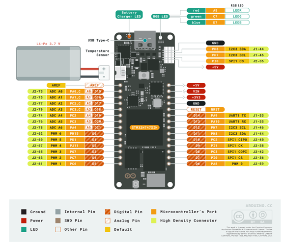
Figure 4: The Portenta H7 Lite Connected Pinout. Source: Arduino
The hardware for this project consists of two circuit boards. The first is the Portenta H7 Lite Connected board which will contain the "brains" and the communication of the project. The second is the LSM9DS1 accelerometer breakout board which will detect the X, Y, and Z motion induced into the frame of the CNC milling machine as the motors rotate during a milling operation. It is recommended that the accelerometer board connect to the Portenta via wires long enough so that various mounting points can be tested for your particular CNC milling machine. This prototype was tested on a second-generation desktop CNC mill from X-Carve. However, it should work on any milling machine.
- Insert a four-pin header row into the LSM9DS1 breakout board. Since this project uses I2C serial communications, insert a header into the side with the
GND,VDD,SDA, andSCL - Wire the
GNDandVDDpins of the LSM9DS1 board to theGNDand3V3pins, respectively, of the Portenta board. - Wire the
SDAandSCLpins of the LSM9DS1 board to thePH8andPH7pins, respectively, of the Portenta board.
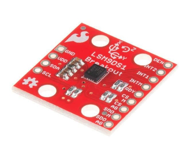
Figure 5: Breakout form factor of the LSM9DS1 IMU. Source: Mouser
Setting up the Software Development Toolchain
To develop the firmware for this project, we will leverage the new Arduino 2.0 IDE available to download for free from here. After the software is downloaded and installed, a few housekeeping measures need to be completed before the code can be edited. Follow these steps to get the IDE ready for programming the Portenta H7 Lite Connected.
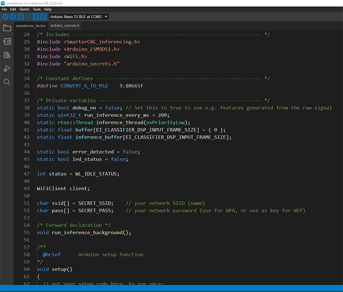
Figure 6: The new Arduino IDE 2.0 adds new features such as a debugger. Source: Green Shoe Garage
- Click
Tools > Board > Board Managerfrom the toolbar. - Type "Portenta" into the search bar.
- Select
Arduino Mbed OS Portenta Boards by Arduinofrom the search results. - Click on
INSTALL
It is also necessary to install the appropriate library files for the LSM9DS1 breakout board. To do so, follow the procedure:
- Click
Sketch > Include Library > Manage Librariesfrom the toolbar. - Type "LSM9DS1" into the search bar.
- Select
Sparkfun LSM9DS1 IMUfrom the search results. - Click on
INSTALL
In addition, the Edge Impulse platform requires the following dependencies to be installed on your computer:
- Python (version 3.9 or greater)
- Arduino CLI
- Edge Impulse Command Line Interface (CLI) Tool Suite. NOTE: As of the time this article was written, installing via the npm package manager on Windows is giving errors. The suggested workaround is a PowerShell script available on Edge Impulse's CLI GitHub repository (https://forum.edgeimpulse.com/t/problems-installing-edge-impulse-cli/1954/6)
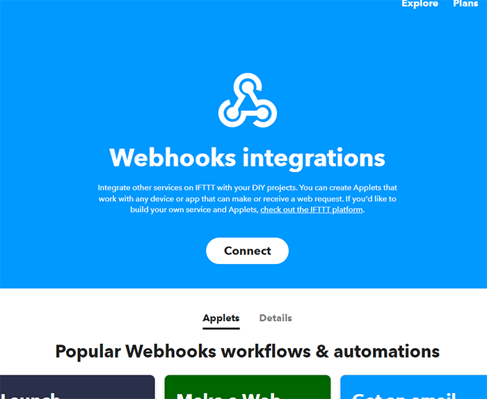
Figure 7: IFTTT webhooks allow IoT devices to interact with other services via a simple HTTP request. Source: IFTTT
Lastly, it is necessary to set up an account with IFTTT. This project leverages the IFTTT webhook technology to trigger the sending of the notification email. An IFTTT account can be established here. A tutorial on how to set up a webhook can be found here.
Software Development
The codebase for this project is written in C. But before we begin to develop the application's unique software, we must first leverage the services of Edge Impulse to develop a machine learning algorithm specific to our machinery and instrumentation. As an added bonus, it will automatically generate a code library for any ARM-based Arduino platform. First, we must acquire training data from our accelerometer and get it into the Edge Impulse cloud-based training environment. To do so, leverage the Data Forwarder tool from the Edge Impulse CLI tool suite. The protocol is straightforward. The Portenta will send the accelerometer data over the serial port at a baud rate 115,200bps. Each reading will consist of the three values for the X, Y, and Z-axis, one set of readings per line. Each of the three values should be separated by a comma, but there should be no comma following the last value of each line.
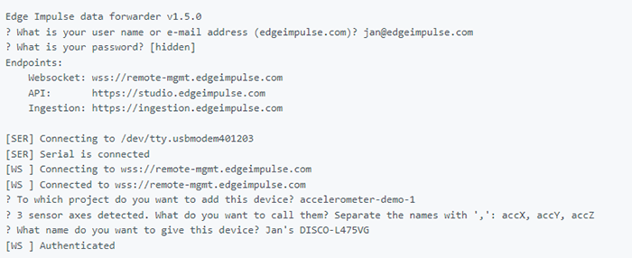
Figure 8: Edge Impulse's Data Forwarder provides a convenient way to send training data from embedded device to the cloud. Source: Edge Impulse
For this project, we will consider three operating states that the milling machine could find itself in at any given time. These states are:
Idle: This is the mode the mill machine will be in before and after the machinery is running normally. There will be little, if any, motion induced by the stepper motors of the router's spindle.Operating Normally: This is the state that the milling machine will be in while milling an object under normal conditions.Error Detected: Should an error occur that causes extreme vibrations (such as motor failure or debris hindering movement of the spindle), the machine will be assumed to be in an error state.Uncertain: A default state should the neural network have low confidence in the machine being in one of the three previous states.
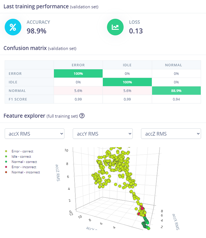
Figure 9: Edge Impulse makes training a NN a simple matter of "click-and-drag" via the web browser. Source: Edge Impulse
Key Files
The critical files for this project include:
smartercnc_fw.ino: Contains the setup routines, the main loop for the project, and a few support functions to interact with the sensors and allow the device to communicate with the machinist via the SMTP email protocol.smarterCNC_inferencing.h: This file contains the inferencing engine that Edge Impulse will generate after training your neural network for your particular machinery and sensors.arduino_secrets.h: Holds the unique variables for your particular wi-fi network (SSID and encryption key) and your unique IFTTT API key that will be needed to send an email via the IFTTT service.
Key Variables and Constants
You might want to be aware of a few variables and possibly tweak them depending on your particular design choices. These variables can be found in smartercnc_fw.ino:
#define CONVERT_G_TO_MS2 9.80665f: Suggested conversion factor to translate the G force reading to an acceleration with a unit of measure in m/s2. Tweak if desired, but this should work for most.static bool debug_nn = false: Set this to true if you wish to see a more verbose output of debugging information.const char *prediction: This variable holds the most recent prediction of the health status of the milling machine based on current accelerometer readings. It can be set to four possible states:Idle, Error, Normal, Uncertain.static bool error_detected = false: Set true the first time an error state is detected.static bool led_status = false: The LED_BUILTIN of the Portenta H7 board is active low. In other words, setting the pin to LOW will illuminate the LED. Setting the pin HIGH will turn the LED off.
These variables can be found in arduino_secrets.h:
#define SECRET_SSID "PortentaAccessPoint": The name of the wi-fi network the Portenta should connect to for wireless communications.#define SECRET_PASS "123Qwerty": The password to connect to the wireless network.char HOST_NAME[] = "maker.ifttt.com": The URL that the Portenta should submit a POST request to when it wants to send a message to the machine operator. In this case, we are using the IFTTT service to send an email.string PATH_NAME = "/trigger/event-name/with/key/your-key": This is how we validate with IFTTT that we are the legitimate user of this webhook.string queryString = "?value1=Error": You can append the HTTP request with any type of data; in this case, we are telling the IFTTT webhook that the machine is in an error state.
Key Functions
The smartercnc_fw.ino file contains the initialization code, the main loop, and support functions for the project. The support functions include:
void handle_error_detection(): This function is triggered when the neural network sets the prediction variable to "Error." This is where you should add any additional function calls to any other functionality to your project to meet your unique needs.void send_email(): This function leverages the IFTTT.com infrastructure and their webhook functionality. In short, when you make an HTTP request (http://maker.ifttt.com/trigger/event-name/with/key/your-key?value1=Error), IFTTT will, in turn, send an email to your desired recipient. This method has numerous advantages, including:- No need to save email password in Arduino firmware
- Works with a variety of embedded platforms with any type of Internet connectivity.
- There is no need to reflash firmware if the recipient's email address changes; just change it on the IFTTT website.
Final Assembly and Installation
Now that the firmware has been uploaded into the Portenta board, it's time to mate the electronics to the milling machine. It is essential to mount the accelerometer in the same manner (location and orientation) as during the data collection phase of training the neural network. Failure to do so may result in false-positive and -negative results. Here is the procedure to mount the project to the milling machine:
- Mount the accelerometer to the milling machine. Again, make sure to mount the accelerometer in the same manner (location and orientation) as it was during training.
- Insert the Portenta board into its enclosure, if so desired.
- Mount the Portenta board to the milling machine. Ensure wires connecting the accelerometer and Portenta are safely routed around any moving components of the milling machine.
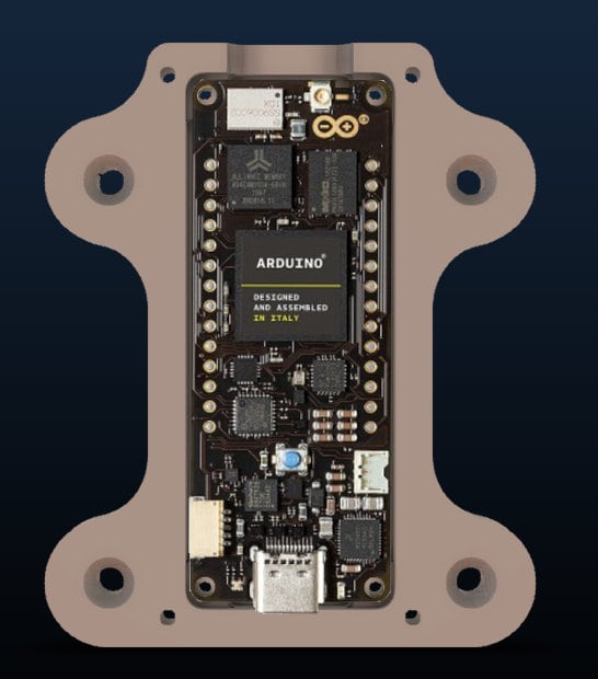
Figure 10: Portenta H7 Lite Connected inside its housing. Source: Green Shoe Garage
- Zip-tie the wires as appropriate to ensure they remain out of the way during operation.
- Connect the Li-Po battery to the Portenta board at the
J4connector.
Lastly, here are a few troubleshooting tips:
- Ensure the Li-Po battery has been fully charged.
- Verify all wires are securely connected to the PCBs.
- Check to make sure that the
SDAandSCLwires weren't reversed. Likewise, ensure the3VandGNDwires weren't accidentally reversed. - Verify the X, Y, Z axis of the accelerometer. Mount the accelerometer in the same manner (location and orientation) for both training and normal operations.
The most accurate results were attained from our testing when the accelerometer was mounted as closely as possible to the motor that controlled the spindle that holds the end mills.
Project in Action
With the project finally assembled and installed, it's time to verify the operation. Set up the milling machine to mill a simple object. Once the milling operation has begun, press the reset button on the Portenta to start monitoring the health of the CNC machine.
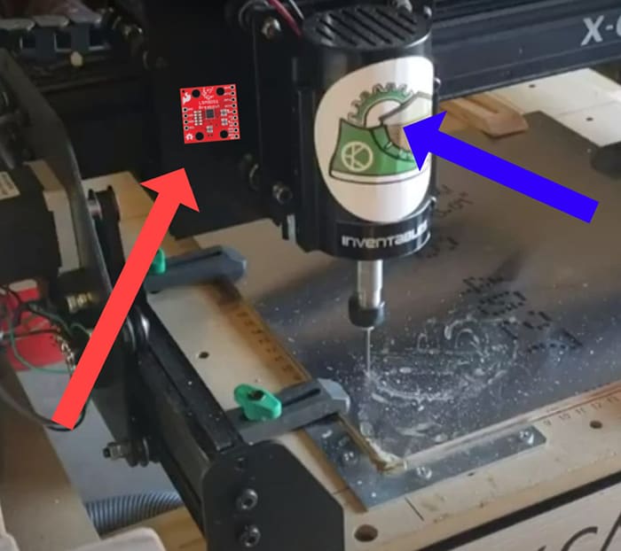
Figure 11: For best results, try mounting the accelerometer (RED ARROW) as close to the spindle motor (BLUE ARROW) as possible. Source: Green Shoe Garage
It will take a few seconds for the firmware to start monitoring the health of the milling machine. During this time, the operator should remain present to ensure safe operations of the equipment. Be sure to wear appropriate safety gear such as eye protection.
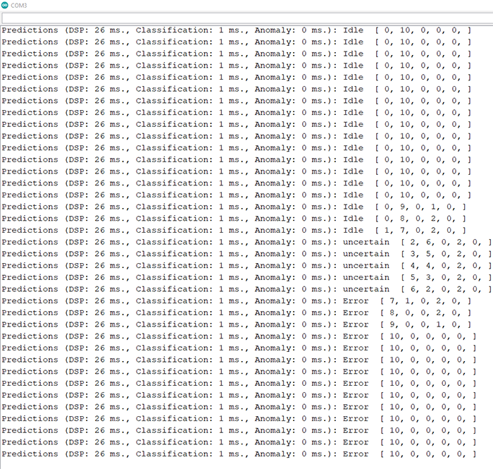
Figure 12: Debug data via the Portenta's serial port. Source: Green Shoe Garage
During normal operation, the built-in LED will be solid. When an error is detected, the LED will flash, and an email notification will be sent off to the machinists. The source code is available for you to modify as you see fit. Consider adding audible alarms or perhaps switching over the communications to a Bluetooth connection.
Conclusion
It is not necessary to invest tens of thousands of dollars to retool your rapid prototyping business. Arduino's latest release, the Portenta H7 Lite Connected, is an industrial-grade embedded platform designed to allow small companies specializing in rapid prototyping to upgrade their legacy CNC milling machines with technology for remote monitoring of their health and communication over the Internet.