GaN HEMTs Power Electric Motor Reform
The demand for compact yet powerful electric motors brings new challenges for design engineers. To maximize power output from smaller motors, engineers are turning to a high-voltage and high-frequency operation. Silicon (Si) metal-oxide semiconductor field-effect transistors (MOSFETs) and integrated-gate bipolar transistors (IGBTs)—upon which conventional switch-mode inverters (a vital element of modern electric motor controls) are based—are struggling to cope with these operational demands. Limited power density and breakdown voltage thresholds restrict drive voltages and the rapid switching required for high-frequency operations pushes up power losses. The result is inefficiency and heat buildup.
Gallium nitride (GaN) high electron mobility transistors (HEMTs) offer an alternative in place of MOSFETs and IGBTs for high-voltage and high-frequency motor-drive applications. These wide bandgap (WBG) semiconductor devices are opening up new applications for high-power density motors because they are able to handle higher voltages, currents, temperatures, and switching frequencies with much lower losses than silicon transistors. The commercial availability of integrated GaN HEMTs and driver inverter stages for high-power-density electric motor applications is easing the adoption of the new technology.
GaN HEMT inverters are complemented by a new generation of ceramic capacitors that can handle the high-voltage spikes and surges that threaten to overstress conventional direct-current (DC) link components inherent to high-power-density electric motors.
In this article, the challenges to components used in the power stages of high-power-density electric motors are described, and GaN HEMTs and high-performance ceramic capacitors are proposed as a solution.
Advances in Electric Motor Design
Designers are demanding smaller, lighter electric motors that enhance existing products and enable use in a wide range of new applications. High supply voltages and control frequencies promise a solution.
The Advantages of a High-Voltage Operation
Nominal motor power is the product of the supply voltage multiplied by current (V x A). Traditional electric motors operate at low voltages (<1,000V) requiring the motor to run at high current to generate high power. The downside of high-current operations is the need for larger coils, which increases coil resistance and, in turn, lowers efficiency and raises temperatures. High voltages (≥10kV) lowers current requirements allowing the use of smaller coils. The downside is that the motor components (including the motor drive electronics) must be able to handle the high voltages, which limits options and increases costs. A second downside is that small coils feature low inductance windings, which are less able to damp the current ripple generated by switch-mode power supplies. Such current ripple can lead to electromagnetic interference (EMI) problems.
The Advantages of a High-Frequency Operation
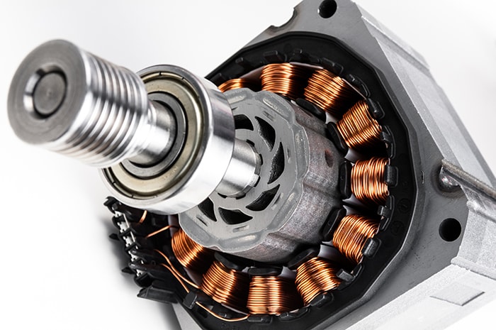
A common type of modern motor is the three-phase alternating current (AC) type, which is driven by sequentially applying current to each phase (winding) of the motor. The motor rotor is pulled around by the rotating magnetic field generated by the windings, and its speed is proportional to the operating frequency (Figure 1).
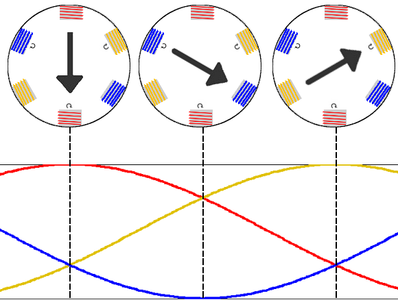
Figure 1: Sinusoidal signals applied to each phase of an induction electric motor generate a rotating magnetic field that drags the rotor around. (Source: Sciencing)
Pulse-width modulation (PWM) is superimposed on the base operating frequency to enable control of parameters such as start-up current, torque, and power. The switching of semiconductor transistors (typically MOSFETs or IGBTs) determines the PWM waveform.
A key advantage of high-frequency PWM is that current ripple—an artifact of the AC input after rectification—is reduced, overcoming one drawback of smaller coils. Reduced current ripple requires smaller, less expensive passive components for filtering. The high-frequency operation also reduces torque ripple—the uneven electromotive force that can result from a less-than-perfect sinusoidal input to the motor coils—that can cause motor vibration and premature wear.
Overall, high-frequency switching increases power density (power produced per unit volume), leading to smaller motors with the same output as larger devices.
Conventional Motor Drives Reach Their Limits
Conventional three-phase AC motors run at voltages up to 1,000V and switching frequencies up to 20kHz. Such operating parameters are well within the capabilities of inexpensive and commercially widespread silicon MOSFETs used to construct the inverting bridges in the final stage of the motor drive.
However, silicon transistors reach their limits in high-power-density motor applications. First, the components’ relatively low breakdown voltage limits supply voltages; second, the transistors’ switching losses—caused by residual resistance and capacitance every time the transistor flips from on to off—rapidly outweighs efficiency gains as the operating frequency climbs; and third, because of a relatively long switching time, the devices reach a threshold beyond which a higher frequency operation is not possible.
IGBT's higher breakdown voltage offers some respite, allowing engineers to increase operating voltages and operating frequencies. But as the operating frequencies climb above 50kHz, the IGBTs begin to suffer from unacceptable switching losses and can’t switch fast enough.
The GaN HEMT Advantage
While silicon forms the mainstay of the electronics industry, other semiconductors are routinely used for specialist applications demanding a high-voltage and high-frequency operation or needing a high-temperature tolerance. These alternative semiconductors are characterized by a wide bandgap (WBG)—the measure of the energy required to free an electron for conduction in a semiconductor—which markedly changes the electrical properties of the material compared with silicon. WBG semiconductors have a bandgap of 2 to 4eV compared with silicon’s 1 to 1.5eV. GaN is an example of a commercially available and proven WBG semiconductor.
Properties of WBGs
In silicon MOSFETs, temperatures above 100°C compromise controlled switching because some electrons gain enough energy from the heat (rather than a switching voltage) to escape the parent atom. Because the electrons of a WBG semiconductor require more energy to escape from an atom and contribute to conduction, the same effect doesn’t occur in GaN transistors until the temperature reaches around 300°C.
WBG semiconductors exhibit a higher breakdown voltage (above 600V) than silicon. The reasons for this are complex but are in part due to a property called electron saturation velocity (also called electron mobility). The higher mobility allows the WBG semiconductor material to handle twice the current density (A/cm2) of silicon. This property also allows a GaN HEMT to switch in about one-quarter of the time it takes a silicon MOSFET to flip.
All semiconductor transistors exhibit an on-state power loss due to parasitic and electrode resistance. Other factors such as inter-electrode capacitances also contribute to power losses. The losses occur every time a transistor is switched and are therefore proportional to the switching frequency and motor current. The parasitic and electrode resistance of GaN HEMTs is about half that of a silicon MOSFET, and the inter-electrode capacitances are about one-fifth. The difference dictates that GaN HEMT switching losses are around 10 to 30% those of a silicon MOSFET for a given switching frequency and motor current. IGBTs exhibit lower switching losses at high frequencies than MOSFETs but are still much less efficient than GaN HEMTs.
A final advantage of GaN HEMTs is that the transistors don’t suffer from reverse-recovery charge—the dissipation of minority carrier charge left over when a silicon MOSFET switches from on to off—which leads to switch current overshoot (ringing) in silicon MOSFETs, potentially contributing to EMI.
The Use of GaN HEMTs in Electric Motor Design
The electrical properties of GaN HEMTs make them an attractive proposition for engineers designing compact, high-voltage, and high-frequency electric motors. In summary, the devices offer the following upsides:
- High breakdown voltages, which encourage the use of higher (greater than 1,000V) input voltages
- High current densities, enabling GaN-based components to shrink with no reduction in power-handling
- Rapid switching capabilities, which allow a high-frequency (200kHz and above) electric motor operation
- High-frequency operation, which limits output current ripple and allows a reduction in filter component size
- Low switching losses, limiting power dissipation and improving efficiency
- High-temperature resistance, which permits the use of smaller heat sinks
- High-level integration, allowing GaN HEMTs to be fabricated on a chip (unlike silicon power components).
- Reduced bill of materials (BOMs) and solution sizes, because in motor drive solutions GaN HEMTs can handle freewheeling current without the need of the antiparallel diodes required by IGBTs.
These advantages enable engineers to design highly compact motors with identical output to traditional motors that are more than twice their size, yet with a much lower power consumption. The key downside is that GaN HEMT design demands a high level of expertise in circuit development and testing.
Integrated Solutions Maximize GaN HEMT Benefits
Until recently, silicon MOSFETs and IGBTs retained one key advantage over GaN HEMTs: Their widespread commercial availability. But today, engineers have easy access to GaN HEMT technology. Even better, silicon vendors now provide integrated solutions based on GaN HEMTs, simplifying the inverter stage of a high-voltage and high-frequency AC motor.
Previously, the GaN HEMT was packaged as a discrete device with a separate driver because the transistors and driver components were based on different process technologies and were often supplied by different manufacturers. The downside of this arrangement was the presence of bond wires with parasitic resistance and inductance that added to switching losses. Mounting the GaN HEMT and driver on the same lead frame eliminates common-source inductance, something that is particularly important in fast switching (high di/dt) circuits, because unwanted inductance generates ringing and can cause current protection mechanisms to misbehave. A second key advantage of integrated packages is that thermal sensing can be built into the driver, ensuring the shut-down of GaN HEMTs before damage occurs if an over-temperature situation arises.
Texas Instruments offers a GaN HEMT, high-speed driver, and protection integration with its LMG3410R070 GaN power stages (Figure 2). The product, with expanding portfolio, is the industry’s first 600V integrated GaN power device. The device is an 8mm x 8mm QFN multichip module (MCM), for ease of design. The on resistance is a very low 70mΩ. The gate driver features a built-in buck/boost converter to generate the negative voltage needed to turn the GaN HEMT off.
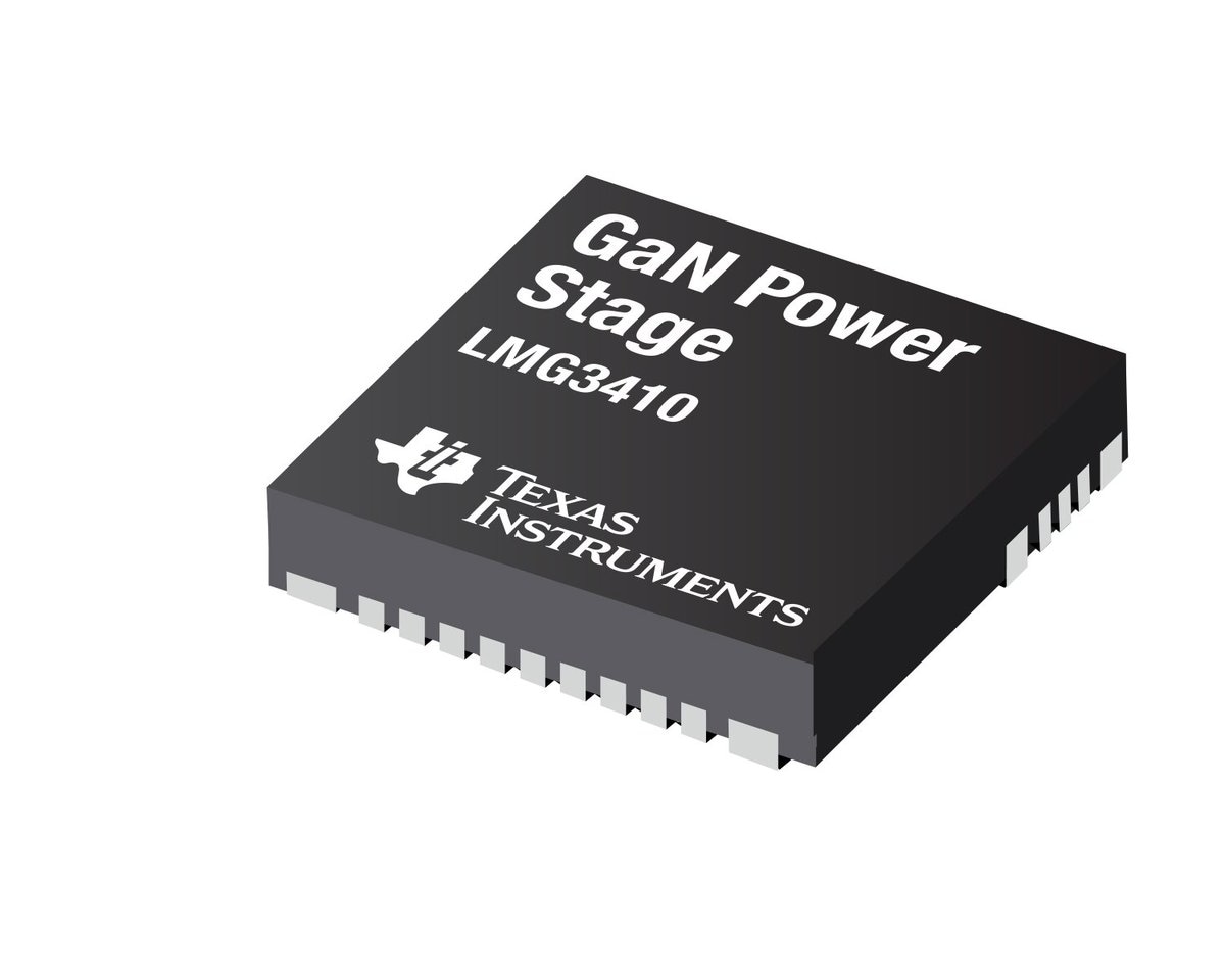
Figure 2: Texas Instruments’ LMG3410R070 GaN power stage integrates a GaN HEMT and driver in a compact package. (Source: Texas Instruments)
A key advantage of the LMG3410R070 GaN power stage is control over the slew rate during hard-switching. Such control is important to limit PCB parasitics and EMI. The TI product uses a programmable current source to drive the GaN gate, which enables the slew rate to be set between 30 to 100V/ns.
Two compact LMG3410R070 GaN power stages in a half-bridge configuration offer the rapid hard switching, low switching loss, low parasitic inductance, and zero reverse-recovery charge required by designers to drive each phase of a high-power-density electric motor (Figure 3).
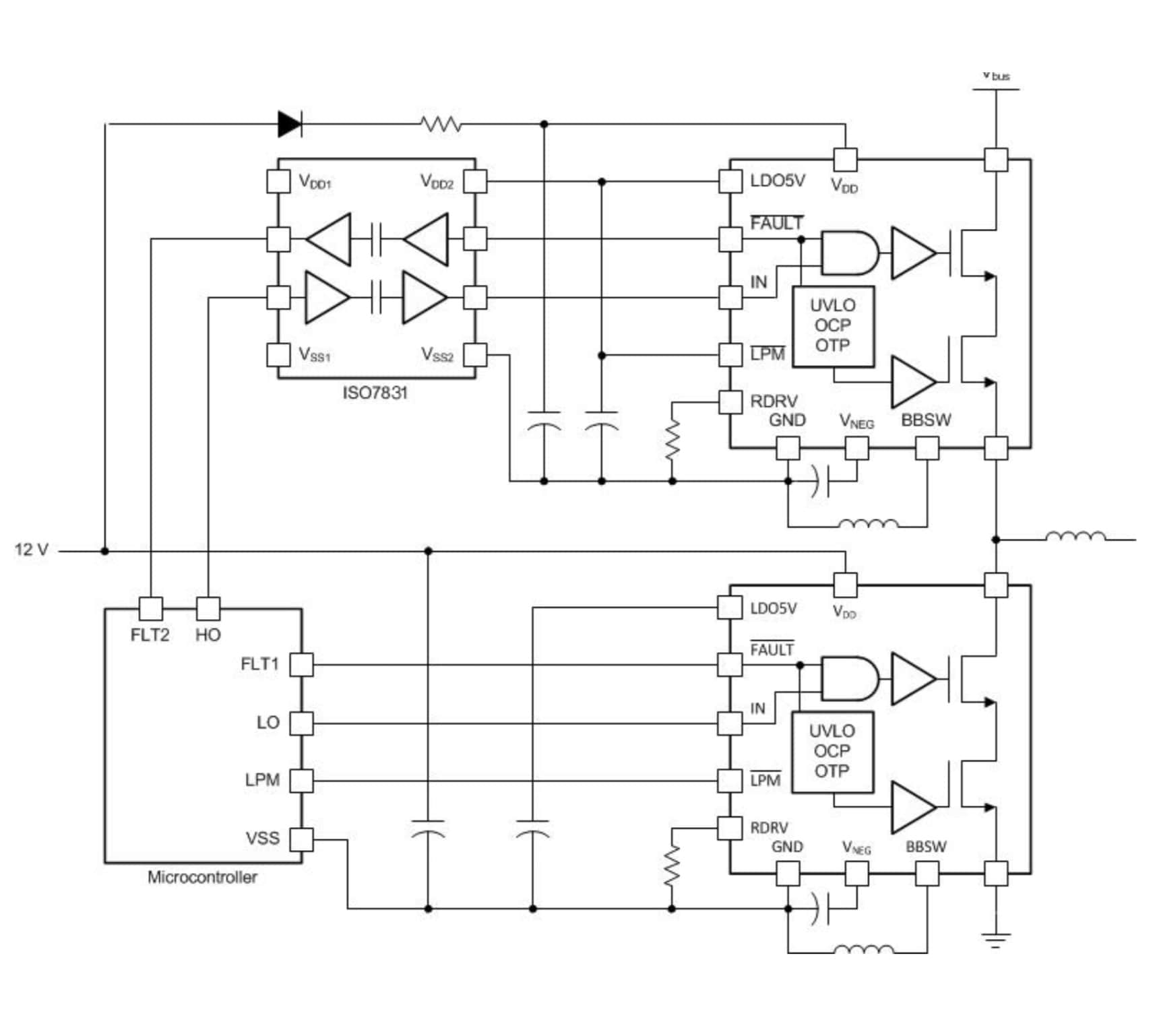
Figure 3: This application circuit schematic shows two Texas Instruments GaN power stages in a half-bridge configuration driving one phase of a three-phase motor. (Source: Texas Instruments)
Building a Drive for High-Performance Electric Motors
A complete AC motor drive solution (Figure 4) comprises three elements: A rectifier (AC/DC converter), a DC link, and an inverter (DC/AC converter).

Figure 4: This motor drive solution schematic illustrates the position of a DC link capacitor. (Source: KEMET)
The rectifier, typically based on a diode or transistor topology, converts a standard 50 or 60Hz AC supply into an (approximate) DC supply. DC power from the rectifier is filtered and stored in the DC link circuit until the inverter uses it. The inverter then converts the DC supply into three sinusoidal PWM signals, each of which drives one phase of the motor.
The DC element performs several key roles:
- Filtering of current and voltage ripple from the rectification stage
- Filtering of rectifier voltage transients that might otherwise damage the inverter’s transistors
- Improving circuit efficiency
- Limiting inductive currents that might otherwise damage the transistors
- Ensuring smooth power transfers to the loads
While a DC link circuit, typically comprising a single capacitor mounted across the power lines between the rectifier and inverter stages of a motor drive, is simple to implement, its importance to the overall performance and efficiency of the electric motor makes the selection of a quality component critical.
DC links operate in challenging conditions involving high-slew rates (dV/dt) and high-voltage peaks, so it is important for a designer to select devices designed to withstand such stress. The KEMET KC-LINK capacitors—which use a ceramic (calcium zirconate, CaO3Zr) dielectric along with nickel internal electrodes—are a good option as they are purposely designed for high-voltage, high-frequency DC link applications.
Key attributes of the KC-LINK devices are the very low equivalent series resistances (ESRs) and equivalent series inductances (ESLs). Low ESR and ESL values contribute to better efficiency, particularly in high-voltage applications. In addition, the capacitors are able to operate at the high frequencies and high temperatures that are common to next-generation electric motor applications. The capacitors can withstand frequencies up to 10MHz and a temperature range from -55 to 150°C. The devices also feature no capacitive shifts with voltage changes, and they are AEC-Q200 automotive qualified.
Conclusion
The commercial availability of WBG semiconductor devices such as GaN HEMTs for electric motor inverters and high-performance capacitors for DC links is meeting the demand from designers for reliable components designed for high-power-density electric motor drives. These key components will enable designers to enhance existing products with compact, lighter, and less expensive motors while extending electric motor use to a wide range of new applications. In addition, a new generation of high-power-density motors will significantly lower energy demands, contributing to a greener planet.
Key Takeaways
- High-voltage and high-frequency motors allow for increased power density and high efficiency.
- The fast switching necessary for the inverter stage of a high-frequency drive causes unacceptable losses in the silicon MOSFETs and IGBTs traditionally used for electric motor applications.
- WBG semiconductor transistors such as GaN overcome this problem.
- Integrated GaN HEMT and driver packages are now available for motor applications.
- High-performance capacitors that can handle high-stress components are also available for the vital DC link element of high-voltage and high-frequency motor drives.