Getting Started With The Hello FPGA Kit

By Rafik Mitry for Mouser Electronics
Published May 11, 2020
A Field-programmable gate array (FPGA) is an integrated circuit (IC) that contains a collection of programmable logic blocks. These logic blocks can be configured to perform a range of functions: from complex logic structures to simple logic gates. The FPGA is, in essence, a reconfigurable IC, meaning it can be reprogrammed after manufacturing to meet the customer's needs. For engineers without prior experience, the common perception is that FPGAs are complex and require specialist knowledge to use. However, Microchip Technology has developed a low-cost, entry-level platform for the less experienced end-user aimed at changing that perception. Called Hello FPGA, we will show how easy it is to get this kit up and running, then flash the FPGA with software demos provided by Microchip: ideal as a starting point before developing your own FPGA applications.
Project Materials and Resources
Access the project's BOM on Mouser's website for the required component:
494-M2SHELLOFPGAKIT - Microchip Technology Hello FPGA Kit
Software:
Project Technology Overview
For this project, we've used the following products and technologies, described in the following sections:
- Microchip Technology Hello FPGA Kit
- Digital Signal Processing
- AI real-time digit recognition
Microchip Technology Hello FPGA Kit
Microchip Technology Hello FPGA Kit is designed for end-users with low to medium field-programmable gate array (FPGA) knowledge. The Hello FPGA board (Figure 1) is based on the SmartFusion 2 FPGA with its Arm Cortex –M3 processor. The board includes the PIC32 microcontroller used to program the SmartFusion2 System on Chip FPGA, monitor power, and other general-purpose functions. The kit also includes Arduino and mikroBUS™ compatible interfaces for more prototyping capabilities.
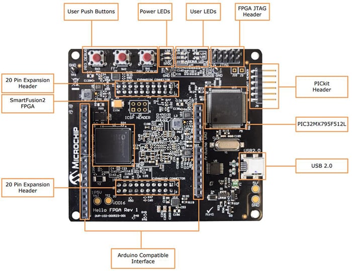
Figure 1: Hello FPGA Board Layout (Source: Microchip Technology)
The Hello FPGA kit consists of:
- an LCD screen
- The Hello FPGA board
- and a camera sensor board
The Hello FPGA Kit demonstrates the following features:
- Digital Signal Processing: with finite impulse response (FIR) filtering and Fast Fourier transform (FFT) on various waveforms
- Artificial Intelligence: Uses parallel processing to do real-time handwritten digit recognition
- Power monitor GUI: FPGA core power measurement in operational and Flash Freeze modes
- Instant ON: Highlighting fast wake-up time from Flash*Freeze (0.03W) mode to fully functional
Let's take a more in-depth look at some of the features.
Digital Signal Processing
Digital Signal Processing (DSP) is one of the most popular technologies used for filtering and analyzing raw data. It uses digital filtering to separate and restore information from a data set. Briefly explained, filters accept an input signal, block specific frequency components, passing the filtered signal to the output. Typically, the classification of a digital filter is based on impulse response duration, which can be finite or infinite.
The finite impulse response (FIR) filter (Figure 2), is a standard filter implementation in DSP in which, as the name suggests, the impulse response is limited to a finite duration. This impulse response is usually defined by the response of the filter to an individual frequency and classified into two main types: frequency bands the filter will pass (passband), and those that get rejected (stopband). FIR filters also typically produce linear phase delay and are always stable. The common types are:
- Low-pass filter: passes low frequencies, attenuates high frequencies.
- High-pass filter: passes high frequencies, attenuates low frequencies
- Band-pass filter: passes frequencies in a given frequency band.
- Band-stop filter or band-reject filter: attenuates frequencies in a given frequency band.
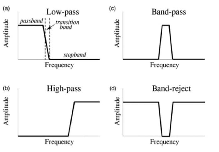
Figure 2: Different types of FIR filters (Source: Microchip Technology)
An FIR filter is usually implemented by using a series of delays, multipliers, and adders to create the filter's output (Figure 3). The input signal is delayed in stages and multiplied by coefficients (hk). The output signal is the summation of all the delayed samples multiplied by the appropriate coefficients.
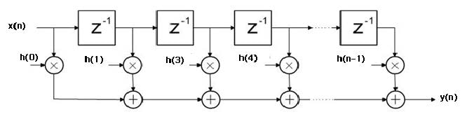
Figure 3: Different types of FIR filters (Source: Microchip Technology)
Because the FPGA has specialized blocks for multiply and add/accumulate functions (MAC), FIR filters are efficient to implement, with different filter properties achievable thanks to the range of MAC structures it's possible to create.
AI Digit Recognition
Another feature the Hello FPGA Kit is capable of is using Artificial Intelligence to recognize a handwritten digit in real-time. Figure 4 shows the block diagram of the AI Digit recognition demo application.
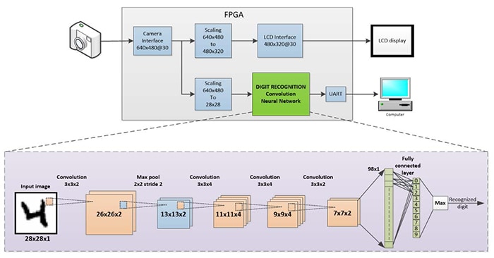
Figure 4: Block diagram of the Hello FPGA AI Digit recognition demo application (Source: Microchip Technology)
Let's see how it works:
- The FPGA receives video stream from camera sensor board with a resolution of 640px x 480px at 30fps.
- The video is scaled down to 480px x 320px to match the resolution of the LCD display.
- The video is further scaled down to 28px x 28px as input to the Convolution Neural Network (CNN) that recognizes handwritten digits in the video stream.
- The LCD shows the final scaled-down image in the top left corner.
This Hello FPGA demo uses a convolution neural network, which is a class of deep neural network commonly used in machine vision and image classification applications. Four convolution layers, a max pool layer, and a fully connected layer are implemented in the network. The network is built for only ten classes of digit from 0 to 9.
Now that we have covered the technologies behind the Hello FPGA kit let's get started with setting it up.
Software Setup
The first requirement is to install the Hello FPGA GUI Application, which is provided by Microchip.
- Navigate to Microchip Hello FPGA resources page
- Click and download the "Hello FPGA GUI application," which can be found under the design files heading. You will need to create an account to be able to download the file.
- Navigate to the downloaded zip folder and extract it. Open the Installer folder and run the setup executable. Install the software and click "Next" when prompted.
- Finally, you'll need to click on "restart" to restart your computer and complete the installation.
Now the installation is complete, double click the "Hello FPGA" desktop shortcut icon to run the Hello FPGA GUI application.
- Connect the Hello FPGA board to a PC using the USB 2.0 A to Mini-B cable included with the kit.
- In the top right corner, select the COM port the board is connected to and click on the connect button (Figure 5).
- In the log output, you should see the message "COM connected".
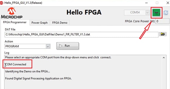
Figure 5: Connecting the Hello FPGA board to a PC (Source: Mouser Electronics)
Flashing the Hello FPGA
Let's flash the board with the first demo.
- In the Hello FPGA GUI app, click on the browse button to view the three available demos (Figure 6).
- Select the first one: 'Demo1_FIR_FILTER_V1.3.dat'.
- Select 'Program' from the 'Action' drop-down menu and then click Run.
After the flash process is complete, restart the board by unplugging the board from your PC, reconnecting it – and then use the same steps as before to connect the board to the GUI app.
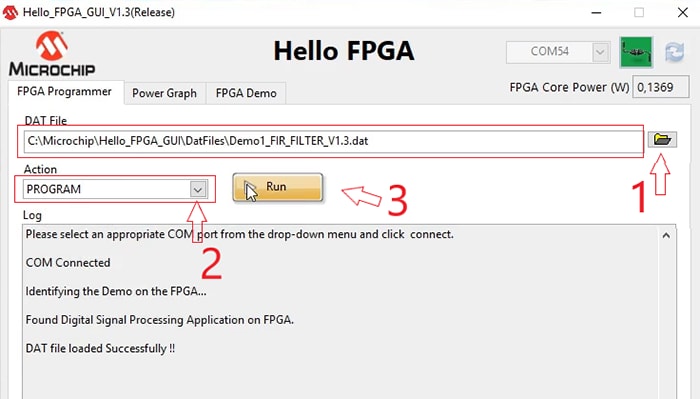
Figure 6: Flashing a demo software to the Hello FPGA kit (Source: Mouser Electronics)
Digital Signal Processing Demo
After the board restart process is complete, follow the next steps:
- Navigate to the "FPGA Demo" tab (Figure 7).
- Under the Input Parameters tab, insert your desired filter. For this demo, let's use a Blackman windowed Low-pass filter with a cut-off frequency of 20MHz.
- Click on Generate Filter.
- Under the Input Signal Generation window, enter the Input frequencies and click 'Generate Signal'.
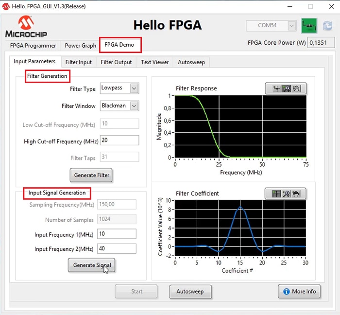
Figure 7: Entering the input parameters for filter and input signal generation (Source: Mouser Electronics)
- Click Start to send the input signal and filter coefficients to the Smartfusion2 FPGA (Figure 8).

Figure 8: Overlook on the Filter Input (Source: Mouser Electronics)
- You'll be redirected to the Filter Output tab (Figure 9), to observe the filtered signal output.
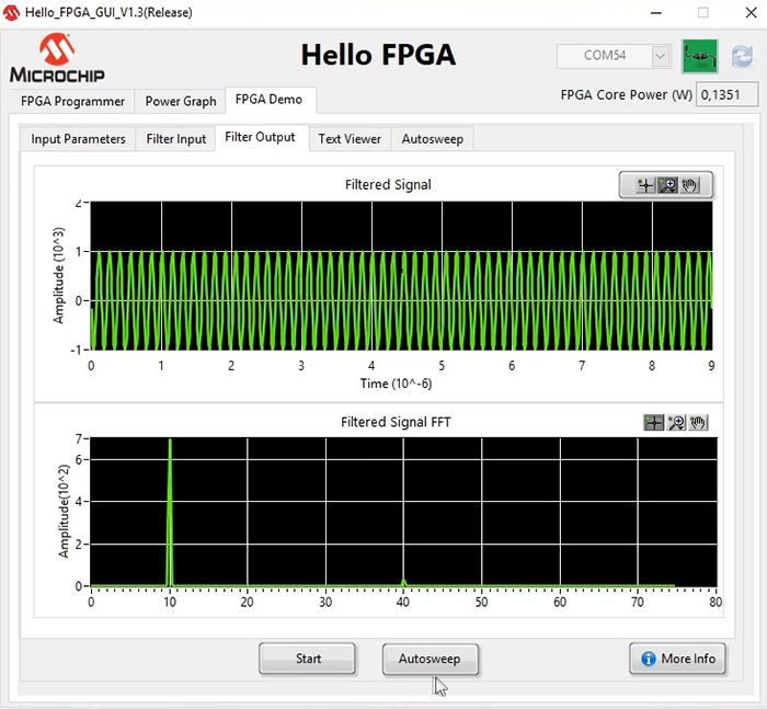
Figure 9: The filter output as per configuration (Source: Mouser Electronics)
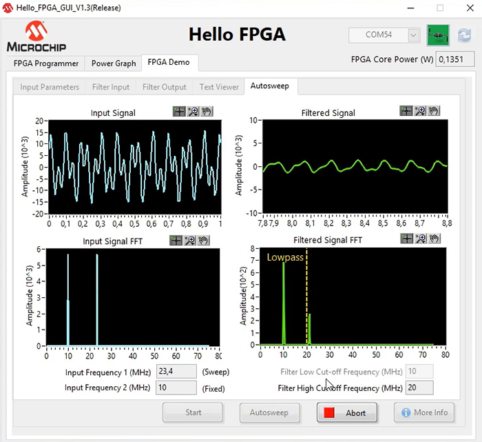
Figure 10: Autosweep function—showing the filtered output on the right. (Source: Mouser Electronics)
Real-time AI Handwritten Digit Recognition Demo
In this example, we will run a real-time Artificial Intelligence handwritten digit recognition demo.
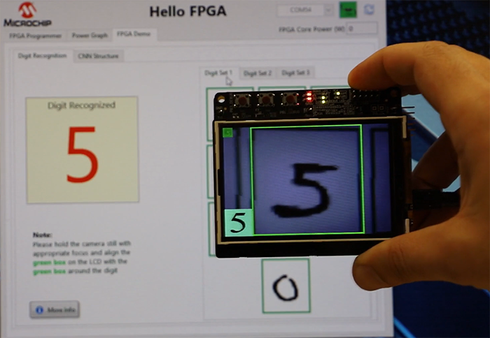
Figure 11: Real-time AI handwritten digit recognition demo (Source: Mouser Electronics)
Core Power Measurement Function
Another feature of the Hello FPGA board is measuring the power in both Active and Low Power Mode. Navigate to the Power graph Tab in the GUI application. By clicking the Flash Freeze Entry, the FPGA moves between active mode and low power mode with the resulting power consumption shown in the graph (Figure 12).
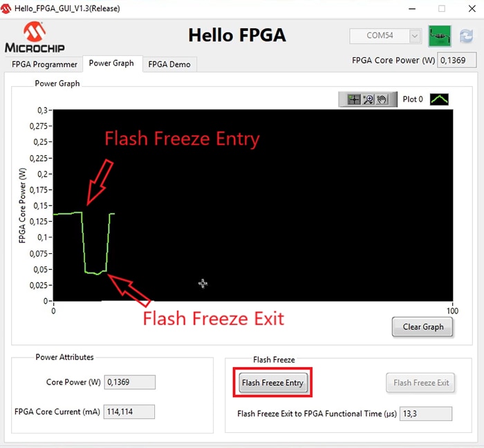
Figure 12: The Hello FPGA core power measurement function (Source: Mouser Electronics)
Conclusion
The Hello FPGA kit is ideal for end-users with low to medium knowledge in FPGAs. The demos provided by Microchip are an excellent starting point to build your FPGA knowledge and begin developing FPGA applications.
- If you click on Autosweep, the GUI will automatically sweep one of the Input signal frequencies through a range of values and then send it to the FPGA for filter operation. The filtered output is shown on the right (Figure 10).
- Go back to the FPGA Programmer tab and flash the FPGA with the digit recognition demo 'Demo3_HF10_DIGIT_CNN_FF_V1.1.dat'.
- Point the camera, so that it aligns the green box showing on the Hello FPGA LCD with the green box on the GUI application (Figure 11).
- The recognized digit is shown on the LCD in the bottom left corner. Note: the model is only trained on the digit set provided in the GUI app.