Spark Cloud Curiosity with Microchip
Connecting the Microchip SAM D21 Curiosity Nano to Medium One IoT Cloud

Image Source: TierneyMJ/Shutterstock.com
By Greg Toth for Mouser Electronics
Published April 20, 2020
The Microchip SAM D21 Curiosity Nano Evaluation Kit is an Internet of Things development board featuring a low-power SAMD21G17D Arm® Cortex®-M0+ based microcontroller with RAM and Flash memory, multiple serial communication interfaces, analog-to-digital and digital-to-analog converters, USB device and embedded host, direct memory access controller, multiple timer/counters, and capacitive touch and proximity sensing. The Medium One IoT Prototyping Sandbox is a cloud-based IoT platform designed to help early-stage developers prototype IoT projects or connect existing hardware to the cloud. In this project, we'll set up an IoT development environment using the SAM D21 Curiosity Nano to read analog and digital sensors and send the data to the Medium One cloud using MQTT. Once the data is in Medium One it can be processed and viewed using programmable workflows and configurable widget dashboards.
Project Materials and Resources
The project BOM lists components used in this project. Additional hardware and software development tools are also identified.
Project BOM
- Microchip SAM D21 Curiosity Nano Evaluation Kit (DM320119)
- Adafruit HUZZAH32
- Two (2) Half-Size Breadboards
- Type-A to Micro-B USB cable
- Medium One IoT Prototyping Sandbox subscription
Hardware
- 02.11 b/g/n Wi-Fi® access point with a DHCP server, Internet connectivity, and without a firewall or proxy that blocks outgoing traffic to the Internet
- Personal computer (PC) running Microsoft® Windows®, macOS® or Linux® operating systems
- Patch jumper wires for connecting breadboard components
- Optional: 100K Potentiometer
Accounts and Software
- Web browser for accessing software download sites and Medium One IoT Platform
- Login account for the Medium One IoT Platform
- Microchip MPLAB X® Integrated Development Environment (IDE)
- Microchip MPLAB XC32 Compiler
- Microchip MPLAB Code Configurator (MCC)
- Application project files available in GitHub repositories
- Arduino® IDE for configuring the HUZZAH32 board
- Serial terminal program such as Tera Term on the PC
- Wi-Fi access point connection details including SSID and password
Project Technology Overview
Microchip SAM D21 Curiosity Nano Evaluation Kit
The SAM D21 Curiosity Nano (Figure 1) is an IoT development board based on the SAMD21G17D microcontroller. The combination of board, microcontroller, and onboard components offers developers a number of features for prototyping IoT designs:
- ATSAMD21G17D Arm Cortex-M0+ based microcontroller with 16 KB SRAM and 128 KB Flash memory
- Up to 48 MHz operating frequency
- Six serial communication interfaces that can operate as UART/USART, SPI or I2C
- Three 16-bit timer/counters
- 32-bit real-time clock and calendar
- 12-bit analog-to-digital converter and 10-bit digital-to-analog converter
- 20 pulse width modulation (PWM) channels
- General-purpose input/output (GPIO)
- 16 external interrupts
- Peripheral touch controller (PTC)
- Capacitive touch and proximity sensing
- Full-speed USB device and embedded host
- User LED and push button
- On-board Nano debugger with Virtual COM port (CDC) and logic analyzer
- USB powered with adjustable target voltage
- Many MCU pins brought out to board edge connectors for connecting to your own peripherals
Technical documentation for the SAM D21 Curiosity Nano can be found here and here.

Figure 1: SAM D21 Curiosity Nano Evaluation Kit (Source: Mouser)
The board is supported by the Microchip MPLAB X Integrated Development Environment (IDE) and connects to a PC using a USB cable that supports programming and debugging from the IDE as well as microcontroller serial port connectivity.
Adafruit HUZZAH32
The SAM D21 Curiosity Nano does not have built-in Wi-Fi Internet connectivity, and for this project, we'll use an Adafruit HUZZAH32 board as a co-processor providing Wi-Fi connectivity and secure MQTT communications. The HUZZAH32 will be programmed with an application that provides AT-style commands that will be controlled by the SAM D21 MCU through one of its serial UART interfaces.
Microchip MPLAB X Integrated Development Environment (IDE)
Firmware programs that run on microcontrollers are typically developed and tested using an Integrated Development Environment (IDE) running on a personal computer. The IDE provides an editor, compiler, linker, debugger, and a mechanism for transferring binary program images to the microcontroller.
The SAMD21 Curiosity Nano can be programmed using MPLAB X IDE, a NetBeans-based IDE that runs on Windows, Mac, and Linux computers. It connects to the SAM D21 Curiosity Nano using a USB cable that supports programming and debugging. MPLAB X IDE can be downloaded for free from the Microchip MPLAB X IDE site.
Microchip MPLAB XC32 Compiler
Application source code is converted into machine code for the SAM D21 microcontroller by the MPLAB XC32 compiler which integrates into the MPLAB X IDE environment.
Microchip MPLAB Code Configurator (MCC)
MPLAB Code Configurator is a free, graphical programming environment that generates seamless, easy-to-understand C code to be inserted into your project. It integrates into MPLAB X IDE to accelerate the generation of production-ready code.
Project Application Source Code Files
For this project, MPLAB X IDE was used to create a set of project source code files that initialize the MCU and peripherals, read sensors, control the LED, and send data to the Medium One IoT Platform through Wi-Fi. The project source code files have been put in a GitHub repository so you can easily download and use them for this project. The project files will be opened in MPLAB X IDE where they'll be compiled and downloaded to the SAM D21 Curiosity Nano board.
You can download the software for the HUZZAH32 board from a second GitHub repository and program it onto the HUZZAH32 using the Arduino IDE.
Medium One IoT Prototyping Sandbox
The Medium One IoT Prototyping Sandbox (Figure 2) is designed to help early-stage developers prototype their IoT project or connect their existing hardware to the cloud. It offers an IoT Data Intelligence platform that enables customers to quickly build IoT applications with less effort. Programmable workflows allow you to quickly build processing logic without having to create your own complex software stack. Configurable dashboards allow you to visualize application data and view real-time data in various formats. Medium One's iOS and Android apps allow you to build simple mobile app dashboards that can communicate with your devices through the IoT Prototyping Sandbox.

Figure 2: Medium One IoT Prototyping Sandbox (Source: Mouser)
IoT devices can exchange data with Medium One through either a REST API or MQTT. More detailed information about the Medium One IoT Prototyping Sandbox can be found here and on the Medium One site.
The Setup (Hardware)
While setting up the hardware be sure to remember that electronic components are static sensitive so handle accordingly.
Personal Computer (PC)
Power up the personal computer and allow it to boot up.
Wi-Fi Access Point
Make sure your Wi-Fi access point is running with an active connection to the Internet and a DHCP server that assigns IP addresses. You'll need to know the access point SSID and security credentials to be used later when configuring the Wi-Fi connection.
SAM D21 Curiosity Nano
Unbox the SAM D21 Curiosity Nano board and set it up as described in the SAM D21 Curiosity Nano User Guide found here. Carefully insert the included pin header strips into the board holes so that the longer portion of the pins faces down from the bottom of the board. The pin holes have a slightly staggered pattern so the pin headers will stay engaged without soldering. You can optionally solder them in for a stronger board assembly.
Adafruit HUZZAH32
Unbox the HUZZAH32 and follow the setup and assembly instructions found here. Follow the steps for soldering in the plain male headers that support plugging the board into a solderless breadboard. Software setup will be covered in the next section.
Breadboard Connections
Two solderless breadboards are used side-by-side as a convenient way to make wired connections between the SAM D21 Curiosity Nano and the HUZZAH32 (Figure 3). Attach the two breadboards together horizontally and insert the SAM D21 Curiosity Nano in the left breadboard and HUZZAH32 in the right breadboard. Connect patch jumper wires between the boards according to Table 1, being very careful to use the correct pin numbers and pin orientations as described in each board's user guide found here and here. Refer to the SAM D21 Curiosity Nano schematic for clarification on pin numbering.
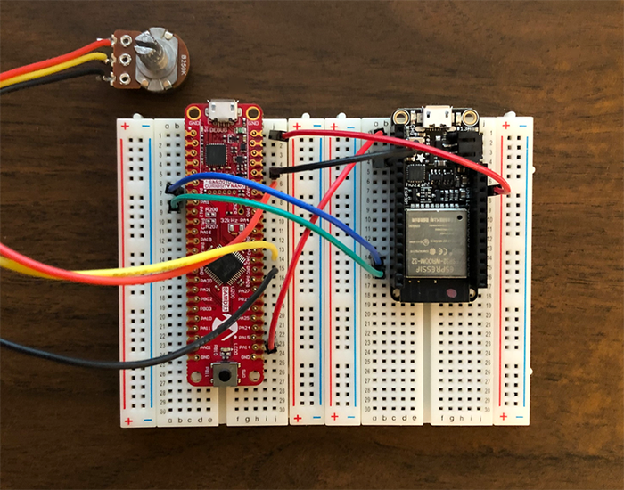
Figure 3: Breadboard Layout and Connections (Source: Mouser)
Figure 3 also shows a potentiometer connected to the SAM D21 Curiosity Nano. This optional component provides an easy way to vary the analog input voltage measured by the SAM D21 analog-to-digital converter. If you don't use a potentiometer you can vary the input voltage manually by connecting a jumper wire from SAM D21 Curiosity Nano PA14 to either GND or VCC_EDGE.
Table 1: Wiring Between SAM D21 Curiosity Nano and HUZZAH32
| SAM D21 Curiosity Nano | HUZZAH32 | Notes | |||
| Pin # | Signal | Pin # | Signal | ||
| 7 | PA08 UART0_TX | RX | Tx -> RX | Serial transmit/receive | |
| 8 | PA09 UART0_RX | TX | RX <- TX | Serial receive/transmit | |
| 48 | VBUS (+5V) | USB | +5VDC | Power | |
| 44 | GND | GND | Ground | Ground | |
| 26 | PA14 | RST | Reset | Hardware reset | |
| 34 | GND | Outside leg of optional potentiometer | |||
| 35 | PA02 ADC0 | Center leg of optional potentiometer | |||
| 43 | VCC_EDGE (+3.3V) | Other outside leg of optional potentiometer | |||
The Setup (Software)
Download and Install MPLAB X, MPLAB XC32 Compiler and MPLAB Code Configurator
Web browse to the Microchip MPLAB X IDE site and locate the MPLAB X IDE installer for your type of PC. Run the installer and make sure the following applications are selected for installation:
- MPLAB X IDE (Integrated Development Environment)
- Device support for 32-bit MCUs
The other items are not needed for this project and can be omitted if needed to save disk space.
At the end of the installation, two web pages will open automatically. One takes you to a page for downloading the MPLAB XC32 Compiler. Download the MPLAB XC32 installer for your operating system and run it to install the compiler on your machine. You can select the free MPLAB XC32 C Compiler by clicking Next in the Licensing Information dialog.
The second web page is for MPLAB Code Configurator. You can either download and install it now from the web page, or you can install it after launching MPLAB X IDE (next step) and install from the Tools > Plugins > Available Plugins menu item.
Plug the SAM D21 Curiosity Nano board into your PC using the USB cable, then launch MPLAB X IDE. If you didn't already install MPLAB Code Configurator from the web page, install it now from Tools > Plugins > Available Plugins > MPLAB Code Configurator > Install and let MPLAB X IDE restart. You can verify whether MPLAB Code Configurator is installed by navigating to Tools > Plugins > Installed and looking for MPLAB Code Configurator in the list of installed plugins.
When MPLAB X IDE launches with the SAM D21 Curiosity Nano board connected and MPLAB Code Configurator installed, you should see a main screen with a Kit Window tab that looks like Figure 4. If it doesn't look like this, go back through the SAM D21 Curiosity Nano user guide and MPLAB X IDE installation documents to make sure all steps were followed. Also, make sure your SAM D21 Curiosity Nano board is connected when you start MPLAB X IDE.
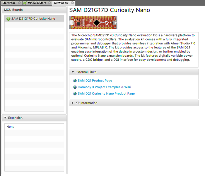
Figure 4: MPLAB X IDE with SAM D21 Curiosity Nano Board Detected (Source: Mouser)
Download and Open the Project Application Source Code Files
Web browse to the GitHub repository https://github.com/IoTDevLabs/ma13_files and find the SAMD21_CNano_ MediumOne_1.0.0.zip file. Download that file to your computer and unzip it to create a directory named sam_d21_cnano_mediumone. Move that entire directory to the MPLABXProjects folder on your PC.
In MPLAB X IDE, select File > Open Project… then navigate into the sam_d21_cnano_mediumone/firmware directory and select sam_d21_cnano_medium_one.X directory, then click Open Project. Afterwards the Projects tab should look like Figure 5.
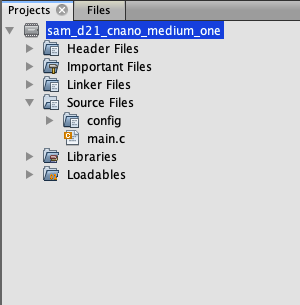
Figure 5: After Opening the sam_d21_cnano_medium_one Project in MPLAB X (Source: Mouser)
We'll come back to the source code files later after setting up Medium One.
Set Up the Medium One Bridge Running on HUZZAH32
Web browse to GitHub repository https://github.com/IoTDevLabs/esp32_mediumone_bridge and follow the instructions for downloading the repository, installing the Arduino IDE and supporting libraries, opening the application program, and uploading the program to the HUZZAH32 board. After the HUZZA32 board is programmed you can disconnect it from your computer.
Set Up the Medium One IoT Prototyping Sandbox
Web browse to the Medium One IoT Platform and log in, after which you should see an initial dashboard resembling Figure 2. If you have trouble logging in, check your Medium One credentials to make sure you're using the latest URL provided with your sandbox subscription. Click Setup > Manage Users > Add New User. Set Username to mydevice, create a password of your choosing and enter it in both password fields, then click Save. In the Manage API Users list, you should see a new user account having Login ID = mydevice and an auto-generated user MQTT ID like Figure 6.

Figure 6: Newly Created User ID With Auto-Generated MQTT ID (Source: Mouser)
Click Setup > MQTT and you should see a Project MQTT ID and a set of port numbers like Figure 7.

Figure 7: Project MQTT ID (Source: Mouser)
Medium One uses MQTT usernames and passwords for authentication. The MQTT username is created by combining the Project MQTT ID, a forward slash, and the user MQTT ID. For example, if the Project MQTT ID is "ZHxxxxxxx0Y" and the user MQTT ID is "sTxxxxxxx8w" the corresponding MQTT username would be "ZHxxxxxxx0Y/sTxxxxxxx8w".
Next, we'll create the MQTT password. Navigate to Setup > Manage API Keys > Add New API Key. Set the description to mydevice, make sure Enabled is check-marked, and click Save. The result should look like Figure 8.

Figure 8: Newly Created API Key (Source: Mouser)
The MQTT password is created by combining the API Key, a forward slash, and the mydevice user password. For example, if the API Key is "PZxxxxxxxxxxxxxxxxxxxxxxxxxxxxxxxxxxxxxxxxxxxMBQ" and the mydevice user password is "AaaaBbbb3" the corresponding MQTT password would be "PZxxxxxxxxxxxxxxxxxxxxxxxxxxxxxxxxxxxxxxxxxxxMBQ/AaaaBbbb3".
The MQTT topic has the following format: "0/Project MQTT ID/User MQTT ID/Device ID".
The Device ID field can be anything and we'll use "mydevice" as the Device ID. For example, if the Project MQTT ID is "ZHxxxxxxx0Y" and the user MQTT ID is "sTxxxxxxx8w" the corresponding MQTT topic would be "0/ZHxxxxxxx0Y/sTxxxxxxx8w/mydevice".
The MQTT username, MQTT password, and MQTT topic strings will get added to the project source code in the next step.
Update Application Source Code Files for Medium One Account Parameters
Set Wi-Fi Connection Parameters
In MPLAB X IDE open project source file main.c in the editor. Find these constants and set them to your own Wi-Fi SSID and password:
- WIFI_SSID
- WIFI_PASSWORD
Set Medium One Connection Parameters
In main.c find these constants and set them to your own Medium One MQTT parameter strings as described earlier:
- MQTT_USERNAME
- MQTT_PASSWORD
- MQTT_PUB_TOPIC
Save the modified file and build the project. Verify the code compiles without errors. If you see compilation errors, check the changes you made to main.c.
Run the Application
Make sure the SAM D21 Curiosity Nano board is connected to the PC through USB and the SAM D21 Curiosity Nano and ESP32 board are wired up as described earlier. Build the program and then download to the SAM D21 Curiosity Nano board. The first time you run the program a dialog might appear (Figure 9) asking to confirm the debugger connection. Select SAMD21G17D Curiosity Nano (PKOB nano) board and click OK.

Figure 9: Board Debug Connection (Source: Mouser)
The program should be downloaded to the board and start running. You can connect a serial terminal program such as Tera Term to the USB serial comm port if necessary to monitor debug messages from the SAM D21 Curiosity Nano while it's running. Set the serial parameters to 115200,N,8,1.
How the Application Program Works
This program was created using the MPLAB Harmony v3 software framework and MPLAB Harmony Configurator. The high-level program flow includes:
- Initialize hardware
- Maintain processing state machine
- Initialize serial connection to ESP32 bridge
- Connect to Wi-Fi via bridge
- Connect to Medium One MQTT broker via bridge
- Periodically read sensors
- Generate JSON formatted MQTT payload messages and send to Medium One MQTT broker via bridge
MQTT Payload Format
MQTT messages are formatted as JSON strings according to the Medium One MQTT payload specification. Here's an example message:
{"event_data":{"iteration":25,"timestamp":3431684,"button":0,"adc":2426}}
Fields:
- iteration = counter that increments by 1 each event_data message
- timestamp = milliseconds since board started
- button = 1 for pressed, 0 for released
- adc = analog-to-digital conversion of pin PA2 with value ranging from 0 to 4095
Try pressing and releasing the push button or changing the analog voltage on pin PA2 to see the data values change.
View Data in the Medium One Dashboard
In the Medium One dashboard navigate to Data Viewer > Data Streams and click raw Events. You should see raw messages (Figure 10) being received from the SAM D21 Curiosity Nano. Click the "+" sign to view message details.
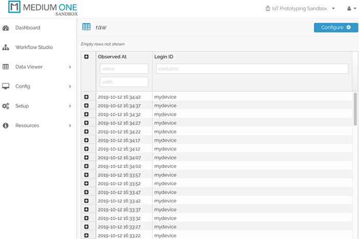
Figure 10: Raw Message Display (Source: Mouser)
Click Dashboard on the top left, then click Add Widget > Single User Real Time Events Stream to add an event stream widget to the dashboard.
In the Select user dropdown, select mydevice. You should now see messages appearing in the Real Time Events Stream widget (Figure 11). Click the save icon in the upper right corner to save your modified dashboard.
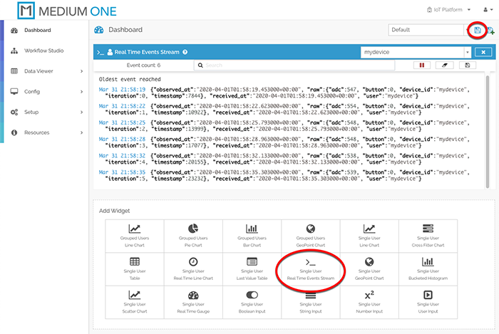
Figure 11: Real Time Events Stream Widget Display (Source: Mouser)
Add More Widgets
To display more widgets, we need to enable specific data fields contained in the message payload. Navigate to Config > Data Streams and click on raw Events. The Schema Map should be pre-populated with fields detected in the incoming messages; however, they are currently disabled. Check-mark the Active box on raw.adc, raw.button, raw.iteration and raw.timestamp, then click Save Data Stream. These fields are now available for use in other dashboard widgets.
Add More Widgets
Back on the dashboard, click the Single User Last Value Table widget and select the mydevice user within the widget. Click the widget's Tag Config icon to the right of the mydevice user selection and check-mark raw:adc, raw:button, raw:iteration and raw:timestamp, then click Save. The Last Value Table should now populate with the most recent received values for each field (Figure 12). Click the Save icon toward the upper right corner to save the updated dashboard.
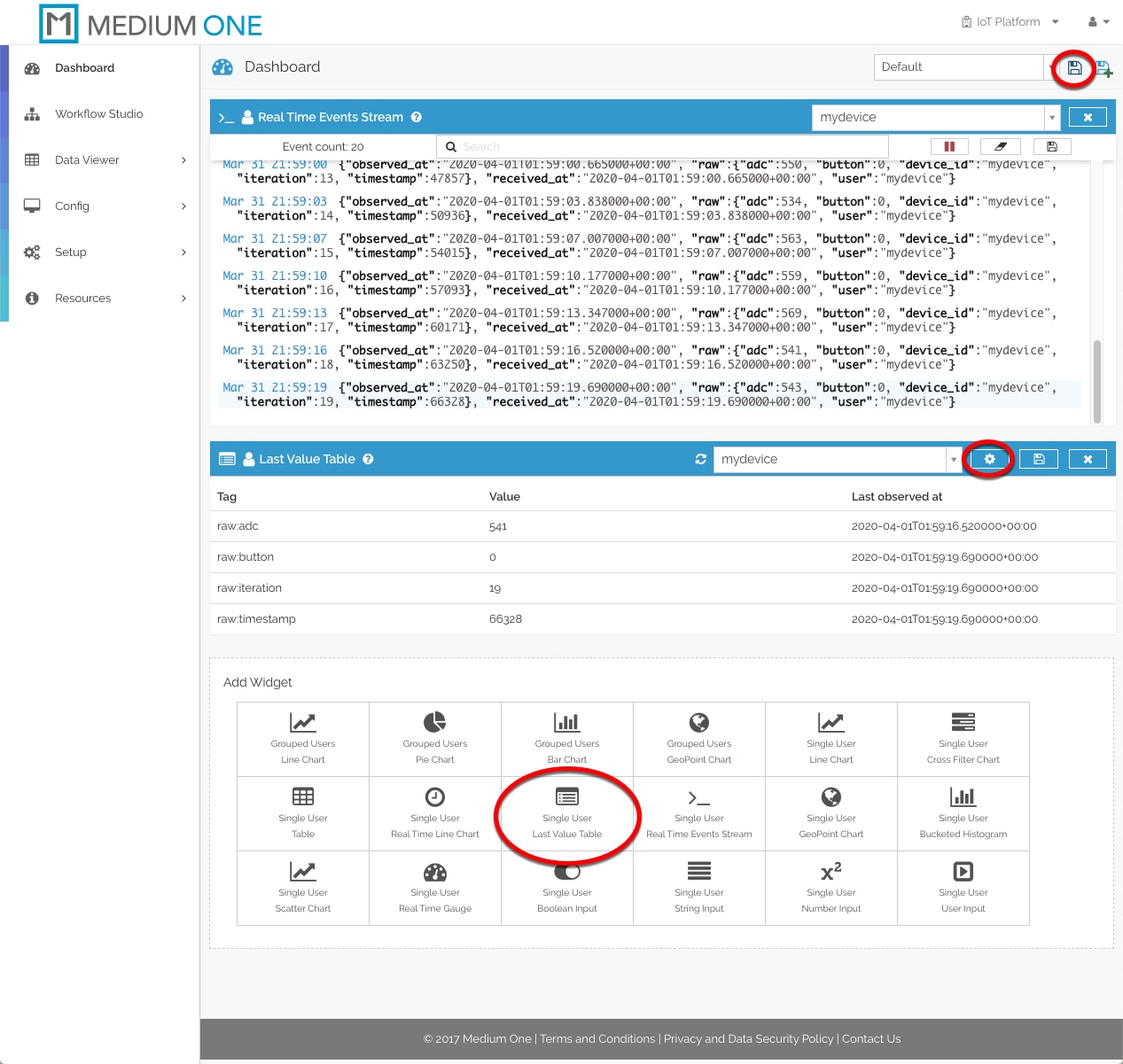
Figure 12: Last Value Table Widget Display (Source: Mouser)
Now let's add dashboard widgets for the adc, button and iteration counter. Click Single User Real Time Gauge and select the mydevice user. Click the widget's Tag Config icon and check-mark the raw:adc, raw:button and raw:iteration rows, then click Save. The updated dashboard should look like Figure 13. Click the dashboard save icon to save the updated dashboard. Try pressing and releasing the push button or changing the analog voltage on pin PA2 to see the gauge values change.
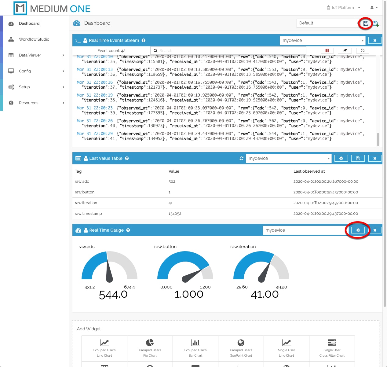
Figure 13: Real Time Gauge Widgets Added to Dashboard (Source: Mouser)
At this point, your SAM D21 Curiosity Nano board is running continuously, periodically reading the push button and analog-to-digital converter and transmitting data measurements to the Medium One cloud. Remember to power off the SAM D21 Curiosity Nano board when you're done, otherwise, the board will continue to send messages to Medium One and consume daily message allotments.
Troubleshooting Tips
- Make sure all breadboard wiring is correct.
- Make sure HUZZAH32 is set up and programmed according to the instructions.
- Make sure MPLAB X IDE is installed and configured according to the instructions.
- View information messages on the SAM D21 Curiosity Nano USB serial port.
- View information messages on the HUZZAH32 USB serial port.
Where to Go Next
This project created an end-to-end sensor-to-cloud application that sends real-time sensor data to the Medium One IoT Prototyping Sandbox. It can be modified and extended in a number of ways and here are a few examples:
- Dive deeper into the application code and board hardware by reading the SAM D21 Curiosity Nano User Guide, the SAMD21G17D MCU datasheet and application notes, the MPLAB Harmony v3 documentation, and studying the source code.
- Add more widgets to the Medium One dashboard, such as a real-time line chart of ADC readings.
- Learn about the Medium One Workflow Studio, which lets you create data processing workflows to transform your sensor data.
- Experiment with the Medium One mobile apps.
- Modify the sensor data publishing interval by modifying the application source code.
- Connect other types of sensors to the SAM D21 Curiosity Nano board and include the data in MQTT messages.