How to Build a Smart Mailbox, Get Alerts
A Step-By-Step Guide to Create an IoT-Enabled Post Box Using Arduino MKRFOX1200
Tired of checking your traditional mailbox every day and finding it empty? In this project, we will create an easy LPWAN (low-power wide-area) application, which will connect the mailbox to the cloud. By using an Arduino MKRFOX 1200 board and the Sigfox network, the mailbox will send a notification, whenever a letter arrives.
Check this video to see the project in action:
Project Technology Overview
For this project, the following products and technologies, described in the following sections, can be used:
- Arduino MKRFOX1200
- Sigfox
Arduino MKRFOX 1200
Arduino MKRFOX 1200 Development Board offers a practical and cost-effective solution for users seeking to easily add Sigfox connectivity to their projects. It is based on the Microchip SAMD21 32-bit Arm® Cortex®-M0+ Microcontroller and the Atmel ATA8520 single-chip Sigfox RF transceiver. The MKRFOX 1200 offers a rich set of I/O interfaces, low-power Sigfox communication and the ease of use of the Arduino Software Integrated Development Environment (IDE) for code development and programming. All these features make the MKRFOX 1200 Development Board an ideal choice for battery-powered Internet of Things (IoT) projects in a compact form factor. The MKRFOX 1200 board can be powered by an external power pack using two AA or AAA batteries, and can operate for up to six months with typical usage.
What is Sigfox?
Sigfox is a low-power wide-area (LPWAN) network that provides connectivity for the Internet of Things (IoT). Applications that need to send small and infrequent data are a great fit to use with the Sigfox network. Users can send 140 messages per day with each carrying a payload of 12 bytes. Because it is a LPWAN network, the power consumption is very low, which makes it ideal for battery-operated applications. The Arduino MKR FOX 1200 includes a 1-year free subscription to the Sigfox network.
Let's get started!
Project Bill of Materials (BOM)
Access the Project BOM on Mouser.com fro these required components:
(Included is a battery pack and battery holders; only one will be needed. In this tutorial, the battery holders with 2x AA batteries will be used to power the board.)
- 485-ABX00014 – Arduino MKRFOX 1200
- 485-X000016 – Antennas GSM antenna with Micro UFL connector
- 474-PRT-12002 – SparkFun accessories breadboard - self-adhesive (White)
- 485-375 – Adafruit accessories magnetic contact switch
- 474-COM-09609 – SparkFun accessories SPDT slide switch
- 546-BH2AAW – 2x AA battery holder
- 485-258 – Adafruit accessories lithium Ion polymer battery 3.7V 1200mAh
- 932-MIKROE-513> – Jumper wires MALE TO MALE 15CM 10PK
Hardware Setup
In this section, we will walk you through the assembly of all hardware parts:
- Connect the magnetic contact switch to the Arduino (the order of the wires doesn't matter):
- One wire of the sensor to PIN 1 (yellow jumper)
- Second wire of the sensor to GND pin (black jumper)
- Because the MKRFOX 1200 doesn't have an ON/OFF power switch onboard, an SPDT slide switch can be added to switch the board off if needed. Before connecting the battery holders, solder the SPDT switch on the power/voltage wire (red wire).
- Connect the battery holders to the screw terminal block.
- Attach the antenna to the micro UFL connector.

Figure 1: Circuit diagram for the hardware setup (Source: Mouser Electronics).
Software Setup
If it is your first time to use the Arduino MKRFOX 1200, the board must first be configured and registered to the Sigfox network. If you already did this, you can skip to the Code section.
- Install the Arduino IDE on your PC (available to download from Arduino's website).
- Open the Arduino IDE and click on: Tools→Boards→Boards Manager then install the Arduino SAMD Boards (32-Bits ARM Cortex-M0+) package.
- Click on Sketch→Include Library→Library Manager then install these libraries:
- Arduino MKRFOX1200
- Arduino Low Power
- Connect your board to the PC and open the "FirstConfiguration" example, which can be found under: File→Example→Arduino SigFox for MkRFox 1200.
- Flash the code on the board and open the serial monitor.
- Copy the ID and PAC numbers that are printed in the serial monitor, which will be used to register the board to the Sigfox network (Figure 2).
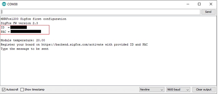
Figure 2: ID and PAC of the Arduino board (Source: Mouser Electronics).
SigFox Backend - Board Registration
The next step is to register the board to the Sigfox network. Navigate to the Sigfox backend (log-in required) and follow the steps there to register your board. Enter the ID and PAC numbers, which you should have copied in the previous step.
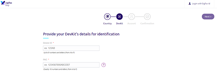
Figure 3: Board registration on Sigfox backend (Source: Mouser Electronics).
Code Overview
Now that everything is set up, flash the smart_mailbox.ino code, which is available on Mouser GitHub repository. The Arduino is programmed to be in sleep mode, until an event occurs. This event is triggered, whenever the mailbox lid is opened. Here are some of the main points in the provided code:
- In the interrupt function, a variable is added to read the battery voltage, which we will use to calculate the remaining battery percentage. This calculation is a rough estimate of the battery's state of charge. Ideally, a battery charging circuit such as this is needed to be able to calculate the battery capacity, which then can be used to calculate an accurate charge. For now, we will go with the calculation shown in the code below. (Figure 4)
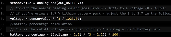
Figure 4: Code snippet - voltage calculation (Source: Mouser Electronics).
- If you trigger the Arduino by moving the two magnets away from each other, you should be able to see a LED blinking on the board. This is because the debug functions are enabled, but this should be disabled after testing to use all the features of the power-saving mode (Figure 5).
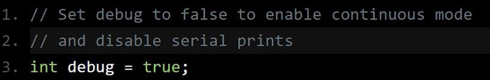
Figure 5: Code snippet - debug mode (Source: Mouser Electronics).
- After disabling the debug functions, it's possible you’ll encounter a problem. The Arduino will get triggered only once and never wakes up again. After searching around, a thread on the Arduino forum addressed the problem and provided a workaround. The problem is located in the Sigfox library. I changed the sigfox.cpp file and added the file in the GitHub repo. If the same problem happens, replace it with the sigofx.cpp file, which is on your PC in this path:
C:/Documents/Arduino/libraries/Arduino_SigFox_for_MKRFox1200/src/. Then reflash your board to update the library on your board.
NOTE: The provided code sends the Arduino module to sleep, which causes the board to not be detected on the COM port. When flashing the board, press the 'RST' button twice, which will cause the board to be detected.
SigFox Backend - Callback Function
In the next step, we will create a callback function. This callback function will transfer the data that is received from the MKRFOX1200 board to your email address.
- Navigate to the Sigfox backend (login required)
- Click on the following: DEVICE TYPE→click on your DevKit→Edit
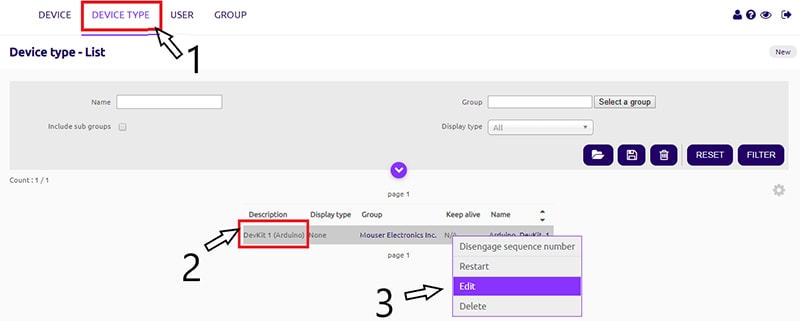
Figure 6: Device settings (Source: Mouser Electronics).
- You will be navigated to this page (Figure 7). Under Downlink mode, make sure Callback is selected.
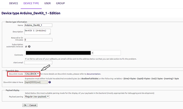
Figure 7: Device Settings - Downlink Mode (Source: Mouser Electronics).
- .Click on CALLBACKS, which is on the left side panel (Figure 7). Navigate to the Callbacks page and click on New.
- Select Custom callback (Figure 8)
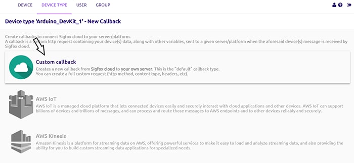
Figure 8: Device Settings - Custom callback (Source: Mouser Electronics).
- In the following we will set up the custom callback function:
- Set the Type→DATA & UPLINK, Channel→EMAIL
- Because we will be sending 1 byte of payload with the remaining battery to the Sigfox server, we have to configure the Custom payload config. The variable "percentage" is an 8-bit unsigned integer, which will be received by the Sigfox server.
- Lastly, add this variable '{customData#percentage}' in the message body. This will show the received battery percentage in the email.
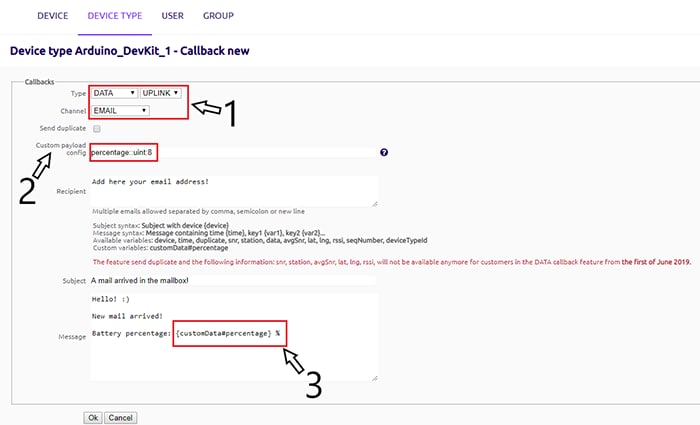
Figure 9: Callback function setup (Source: Mouser Electronics).
Mounting
In the last step, mount all the parts and pieces on your mailbox. All the parts are fixed on the door inside the mailbox. The magnetic contact switch is fixed on the mailbox lid. The antenna is fixed outside the mailbox. (It is recommended not to stick the antenna on a metal surface.)
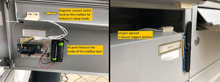
Figure 10: All parts mounted on the mailbox (Source: Mouser Electronics).
Conclusion
This project created an easy LPWAN application that converts the traditional mailbox into a smart one. Using the Arduino MKRFOX1200 makes it very easy to connect to the Sigfox network and start sending data to the cloud. This project can become self-powered by installing a solar panel on the mailbox and connect it to a charging circuit.