Smarter Security with Silicon Labs
Machine Learning + Thread

By Michael Parks, PE, for Mouser Electronics
Published November 14, 2022
Introduction
At face value, the term “Internet of Things” or IoT conjures the following ideas. The IoT is promised to be a ubiquitous, global network of machines that talk to each other while also interacting with, as needed, their human progenitors. In addition to humans and their computers, smartphones, and tablets, the IoT is comprised of potentially billions (or even more) of “headless nodes” that share the goal of sensing and processing both the digital world and the real world. It automates and/or communicates those findings to other machines or humans. Other devices or humans can then take actions based on the data transmitted to them from any number of nodes. The action can be invoked locally or remotely via actuators connected to yet more nodes that comprise the IoT. Crucially, the same TCP/IP-based Internet that we use to browse the World-Wide Web (WWW) and send emails to friends is the communications backbone for the IoT.
With that definition, one would assume that all IoT devices can communicate with each other seamlessly and effortlessly. Nothing could be further from the truth. To prove the point, consider the plethora of IP-based security camera manufacturers: Samsung, Nest, Wyze, Ring, and Anker, to name but a few. One must download the Wyze app to access the video feed from a Wyze camera. To use a Ring camera, one must download the Ring app. You see the problem. While we have a burgeoning IoT, it might be better to refer to it as the Islands of Things.
Enter Silicon Labs and Thread.
Silicon Labs hardware and Thread protocols can be used to create custom, interoperable IoT solutions quickly. To demonstrate how, we are going to build a proof-of-concept that leverages machine learning (ML)-based audio detection algorithms to listen for, and send a notification via Thread, when the system hears the sound of glass breaking.
Project Materials and Resources
Silicon Labs (SiLabs) has recently released their EFR32BG24 Wireless "System-On-A-Chip" (SoC) and associated development kits. For this project, we will leverage the xG24-DK2601B dev kit for these chief reasons:
- Coin cell battery-operated
- Support for mesh IoT wireless connectivity, including Matter and OpenThread
- AI/ML hardware accelerator
- Many onboard sensors for various phenomena include relative humidity, temperature sensor, pressure sensor, ambient light, hall effect (magnetic field), 6-axis inertial orientation/acceleration, and MEMS stereo microphones
Bill of Material (BOM)
You can click this Mouser project share link to access the BOM and the current pricing. As of the date this article was initially written, the BOM cost is about $425 (USD) before applicable taxes and shipping costs. Table 1 lists the items in the BOM.
Table 1: Silicon Labs AI+Thread Home Security Project BOM
Quantity |
Mouser P/N |
Description |
|
2 |
634-XG24-DK2601B |
RF Development Tools xG24 +10 dBm Dev Kit |
|
1 |
409-UCHT01A200464B10 |
Linux-based Single Board Computer with USB ports |
|
1 |
485-4472 |
USB C cable |
|
1 |
340-381243-TRAY |
32GB MicroSD memory card |
Resources
All source files for this project are located on Mouser's GitHub repository. The repository contains all pertinent documentation and source code for you to build your custom solution.
Documentation
The Documentation folder contains graphic files of schematics and other important reference materials.
Software
The folder contains the source code, broken into two major code bases:
edgeimpulse_silabs_thread_mtd_demo: This library contains the code necessary for us to join an OpenThread network as a Full Thread Device (FTD). This will be elaborated on more in the Software Development section.silabs-xg24-dev-kit-ml-meets-thread-slcc-v3: Contains the inferencing engine trained to listen for glass breaking in a home environment.
More details about these files can be found in the Software section below.
Tools
This project assumes that you have access to the following tools:
- Computer with a high-speed Internet connection
- Digital Multimeter (DMM)
Building the Project
This project consists of two components. The first consists of a single-board computer and an xG24 configured as the border router for the OpenThread network. A border router is a device that connects two different networks together. In this case, the OpenThread border router will connect the OpenThread network to an 802.11 Wi-Fi network. The second component will be a standalone xG24 device that will act as the remote listening device that will run an ML algorithm configured to listen for the sound of breaking glass and alert other devices on the OpenThread network. This section will examine the necessary steps to get your project up and running. It is split into the following five subsections:
- Setting up the Software Development Toolchain
- Training the ML Model
- Setting Up the Border Router and Establishing a Network
- Software Development
- Hardware Assembly, Troubleshooting, Project in Action
Setting up the Software Development Toolchain
To develop the firmware for this project, we will leverage the Simplicity Studio 5 (SS5) Integrated Development Environment (IDE) from Silicon Labs. This can be downloaded here: https://www.silabs.com/developers/simplicity-studio
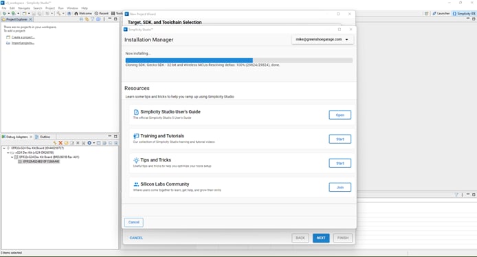
Figure 1: Ensure you have all needed libraries when setting up a new project in Simplicity Studio 5. (Source: Silicon Labs)
Once SS5 is installed on your development machine, launch the application and verify it has been installed correctly (Figure 1). If so, proceed to install the Gecko SDK from the Installation Manager. Next, select Install>Manage Install Packages>SDKs>Gecko SDK – 32-bit and Wireless MCUs>Add from the toolbar. Be sure to select version 4.1.0 or newer.
In addition to the Simplicity Studio IDE, the Edge Impulse platform requires the following dependencies to be installed on your computer:
- Python (version 3.9 or greater)
- Arduino CLI
- Edge Impulse Command Line Interface (CLI) Tool Suite. NOTE: As of the time this article was written, installing via the npm package manager on Windows is giving errors. The suggested workaround is a PowerShell script available on Edge Impulse's CLI GitHub repository (https://forum.edgeimpulse.com/t/problems-installing-edge-impulse-cli/1954/6)
Lastly, we must download a small utility called Simplicity Commander to flash the various firmware we will be developing to the xG24 development board. It is available for Windows, Mac, and Linux. It can be downloaded from here: https://www.silabs.com/developers/mcu-programming-options. Furthermore, the first firmware we need to allow the xG24 to interact with Edge Impulse services can be downloaded here: https://docs.edgeimpulse.com/docs/development-platforms/officially-supported-mcu-targets/silabs-xg24-devkit
Training the ML Model
After getting our tools set up, our first step in building this project is to develop an ML algorithm that is efficient enough to run on the xG24 development board but also robust enough to accurately detect when a glass window is broken. The sound of a window breaking can be considered an anomalous state, as the rest of the time other sounds should be seen as usual and expected. Therefore, the first set of sounds to be recorded will be of the ambient environment with no windows being broken. This should be done with as much variation as would be expected during normal operations. For example, in addition to just the quiet room, it should also contain recordings of people having a conversation, the television on, children playing, etc. Any sounds that might be considered normal should be sent as training data and labeled as normal. The second training data set should feature recordings of glass breaking inside the intended environment. Like the normal recordings, the sounds of the glass breaking should be recorded with various background noises. Of course, the more recordings used for training, the better the prediction results. We will target fifty to a hundred recordings for each label.
The xG24 features high-quality MEMS microphones that can capture sound. We will leverage those microphones to collect two sets of training data. To get the audio recordings from the microphone to the Edge Impulse servers, we will leverage the Edge Impulse command line interface daemon to retrieve the audio data from the xG24 development board via a serial connection. The daemon will then leverage the developer's computer and an internet connection to send the data to Edge Impulse servers for further processing.
We must first plug the xG24 into our developer computer using a micro-USB cable to accomplish this. Next, launch Simplicity Commander (Figure 2) and complete the following procedure:
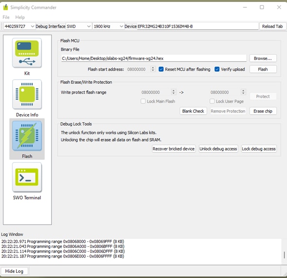
Figure 2: Special firmware must be installed if you wish to use the xG24 for data ingestion to Edge Impulse. (Source: Edge Impulse)
- Select the
Flashoption in the left-hand navigation window. - Click on Browse to locate and select the
firmware-xg24.hexfile downloaded earlier from Edge Impulse's GitHub repository. - Verify that the following fields are set appropriately:
Debug Interface: SWDFrequency: 1900 kHzDevice: EFR32MG24B310F1536IM48-BReset MCU after flashing: CheckedVerify upload: Checked
- Click the
Flashbutton
Now that the xG24 development board is running the training firmware, it's time to collect the audio samples to train the ML model. To do so, we will leverage the Edge Impulse CLI daemon. To get the audio samples into the Edge Impulse training environment, complete the following steps (Figure 3):
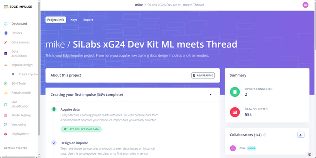
Figure 3: Edge Impulse provides a straightforward walkthrough to develop ML software. (Source: Edge Impulse)
- Navigate to https://studio.edgeimpulse.com in a Chromium-based browser.
- Click on
+Create New Project. - Enter a name for the project.
- Select your license type.
- Click on
Create New Project. - Click on
Audiowhen the new project wizard starts. - Click on
Connect a Development Boardoption to review documentation regarding this method of sending the audio samples to the Edge Impulse data ingestion server (Figure 4). - Click on
Let's Get Startedto begin the ingestion process.
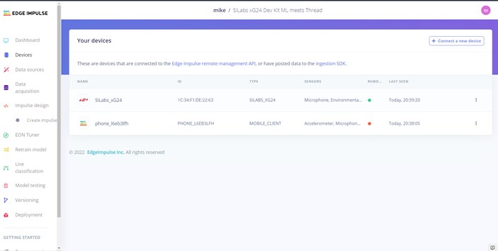
Figure 4: There are multiple options to upload training and test data or upload raw files from the end device or a smartphone,. (Source: Edge Impulse)
Launch a terminal window with the xG24 development board still plugged into your development computer via a micro-USB cable. In the terminal window, execute the following command:
#> edge-impulse-daemon
This will start a text-based wizard connecting the serial data streaming from the xG24 development board to the EI ingestion server via your developer workstation's Internet connection (Figure 5). You will be prompted to enter three pieces of data:
- Edge Impulse username
- Edge Impulse account password
- Edge Impulse project name
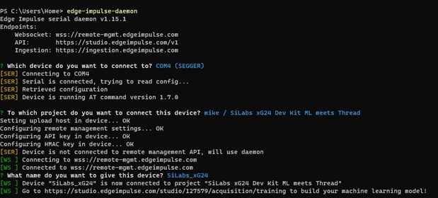
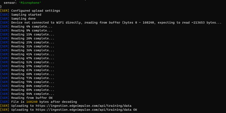
Figure 5: Top: Edge Impulse Daemon allows an embedded device to interact with Edge Impulse cloud services. BOTTOM: Sending microphone data from the xG24 to Edge Impulse (Source: Green Shoe Garage)
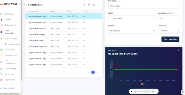
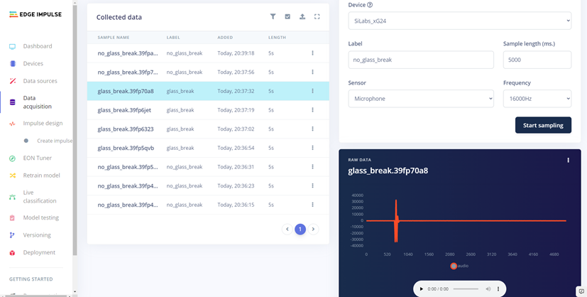
Figure 6: Top: Raw audio files can be viewed and listened to; this one shows background noise. Bottom: This capture shows the sound of glass breaking. (Source: Green Shoe Garage)
Now it's time to collect some data. Per Edge Impulse tutorials, go to the Data acquisition tab. This is where all your raw data is stored, and—if your device is connected to the remote management API—you can start sampling new data (Figure 6). Under Record new data, select your device, set the label to noise, the sample length to 1000, and the sensor to Built-in microphone. This indicates that you want to record 1 second of Audio and label the recorded data accordingly. From this point on, the process will remain the same regardless of whether the development board is used. In the interest of focusing on xG24 unique information, please refer to this tutorial to understand the rest of the training process (Figure 7).
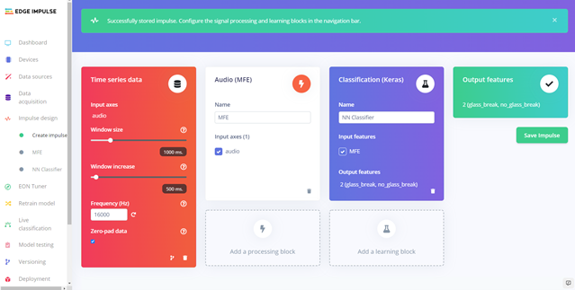
Figure 7: Applying processing and learning blocks is a crucial step in the ML model creation, or impulse design, process. (Source: Edge Impulse)
Lastly, for this project, we are creating two audio datasets with the following labels (Figure 8):
glassbreaknoglassbreak
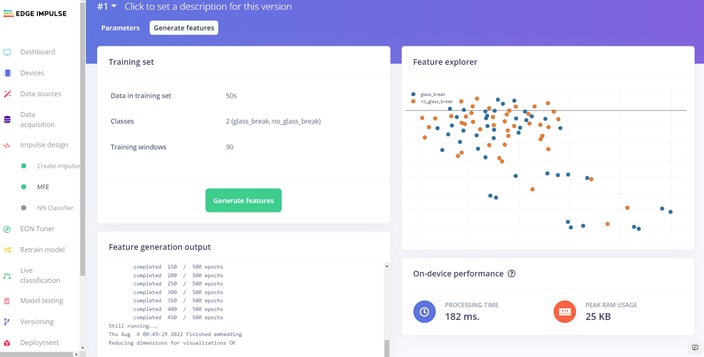
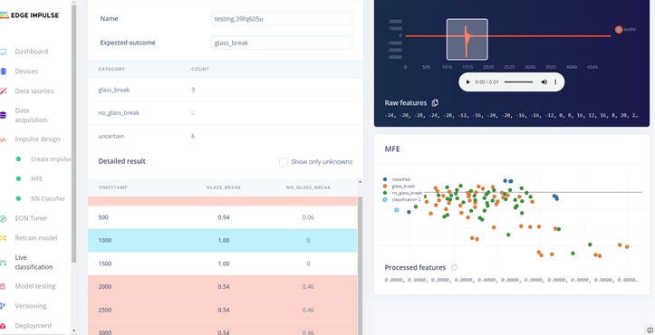
Figure 8: Edge Impulse provides numerous tools to understand how the impulse design is informed by the training data. (Source: Edge Impulse)
You will come to the Deployment process at the end of the Edge Impulse training process. Under the Create Library section, select the Simplicity Studio Component. It is optional whether or not to use the EON Compiler function. For this effort, we will use the Quantized (int8) option. Finally, click Build. Then, save the generated ZIP file to your local machine (Figure 9). Finally, we will import the generated file into Simplicity Studio as a component. For more information, follow this tutorial, but select the xG24 development board.
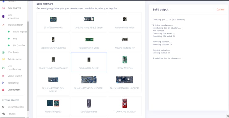
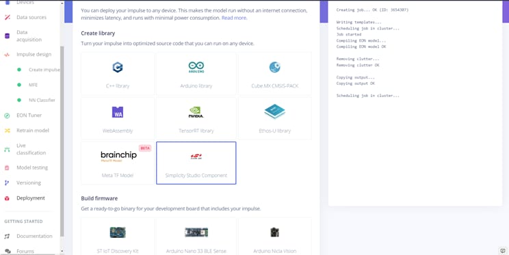
Figure 9: Top: The finished model can be exported as source code that runs direct on supper dev boards. Bottom: It can also be exported as libraries for further development work. (Source: Edge Impulse)
Setting Up the Border Router
Before we get into an overview of the custom source code, let's take a brief look at the basics of the OpenThread communications protocol and setting up a border router. OpenThread is the Google implementation of the Thread protocol that, according to their website, is meant to "make the networking technology used in Google Nest products more broadly available to developers, to accelerate the development of products for the connected home and commercial buildings." The OpenThread specification defines an IPv6-based reliable, secure, and low-power wireless device-to-device communication protocol. OpenThread is highly portable, can run on memory-limited devices, and supports System-on-Chip (SoC) and Co-Processor (RCP, NCP) architectures. In addition, OpenThread implements all features defined in the greater Thread specification for interoperability purposes.
Devices that make up an OpenThread network can be broken into two major node types:
- Router: A node forwards packets for network devices, provides secure commissioning services for devices trying to join the network, and always keeps its transceiver enabled.
- End Device (ED): A node that communicates primarily with a single router, does not forward packets for other network devices, and can disable its transceiver to reduce power. The relationship between the router and ED is a parent-child relationship. An ED attaches to precisely one router. The router is always the parent, the ED the child.
Another key concept that should be understood regarding OpenThread is the notion of a Full Thread Device versus a Minimal Thread Device.
- Full Thread Device (FTD): An FTD can operate as a router (parent) or an end device (child). Its radio is always on, subscribes to the all-routers multicast address, and maintains IPv6 address mappings. There are three types of FTDs:
- Router
- Router Eligible End Device (REED): A FTD that can be promoted to a router.
- Full End Device (FED): A FTD that cannot be promoted to a router.
- Minimal Thread Device (MTD): A device that can only operate as an end device (child). It cannot subscribe to the all-routers multicast address and forwards all messages to its parent. There are two types of MTDs:
- Minimal End Device (MED): A device where the transceiver is always on does not need to poll for messages from its parent.
- Sleepy End Device (SED): A device that is usually disabled occasionally wakes to poll for messages from its parent.
For a deep dive into creating OpenThread networks using Silicon Labs hardware, please check out this tutorial that will dive into the setup. These steps are essential in creating a secure network between the router and end devices. In addition, the tutorial will explain how to establish unique public/private keys (PPK) to communicate securely. Think of it like entering a WPA2 key when connecting to a Wi-Fi network with a laptop but for low-power IoT devices.
For the border router, we will leverage a single board computer (any ARM-based SBC with a Linux OS that can run Docker will be sufficient) and a second xG24 connected via USB. For the sake of brevity, it will be assumed you have an SBC running Linux with root access and connected to the Internet. Be sure to run sudo apt-get update and sudo apt-get upgrade to ensure you have all the latest updates. From there, to install the border router functionality, open a terminal window and enter the following commands, one bullet at a time:
curl -sSL https://get.docker.com | sh
sudo usermod -aG docker $USERdocker pull siliconlabsinc/openthread-border-router:gsdk-4.0.1docker run -d --name "otbr" \
--sysctl "net.ipv6.conf.all.disable_ipv6=0 net.ipv4.conf.all.forwarding=1
net.ipv6.conf.all.forwarding=1" \
-p 8080:80 --dns=127.0.0.1 -it \
--volume /dev/ttyACM0:/dev/ttyACM0 \
--privileged siliconlabsinc/openthread-border-router:gsdk-4.0.1 \
--radio-url spinel+hdlc+uart:///dev/ttyACM0?uart-baudrate=460800 \
--backbone-interface eth0
At this point, it's time to launch the border router is running; we can do that by issuing the following commands:
docker exec -ti otbr sh -c "sudo ot-ctl"docker ps -aqdocker logs [container-id] -f
Software Development
The codebase for this project is written in C. This codebase is broken into two major components (technically three if you consider the Docker image running the border router code, but we aren't modifying that code base). The first is the inferencing engine that will be generated by Edge Impulse. The second is the OpenThread communications stack, allowing the device to communicate with other OpenThread-enabled devices.
Key Files and Folders
The critical files/folder for this project include:
edge_impulse_library.slcc: The output of the Edge Impulse deployment phase is a Simplicity Studio Component (.slcc) file that will be imported into the SS5 and integrated into the listening device source code. For more information on importing with SS5, check out this link.main.c:Most changes will be made to this file for customization.
Key Functions and Variables
The edge_impulse_library.slcc component file contains the project's initialization code, the main loop, and support functions. The support functions include:
void handle_glassbreak_detection(): This function is triggered when the neural network sets thepredictionvariable to "glassbreak." This is where you should add any additional function calls to any other functionality to your project to meet your unique needs. You can consider everything from sending an email notification, updating a flag on a website, blasting a siren, or flashing lights.EI_CLASSIFIER_INTERVAL_MS: Determines how often to run the classifier algorithm against the current sample. This duration should be as short as possible for transient noises like glass breaking.EI_CLASSIFIER_RAW_SAMPLE_COUNT: This determines how long, in milliseconds, a sample period lasts. Again, for very short transient noises like glass breaking, it's better to keep this number small and perform more samples faster. However, you will likely need to experiment with different values to get optimal results in your environment.EI_CLASSIFIER_INFERENCING_CATERGORIES[]: Stores the possible states the inferencing engine must consider. In this case, there are two options,glassbreakandnoglassbreak.Should you desire to have different or additional values, this must be done within Edge Impulse. Repeat the data training and labeling procedures with the new/additional states. Then re-download the source library.
Hardware Assembly, Troubleshooting, and Project in Action
Now that the firmware has been uploaded to the development board, we can test the response of the system under real-world conditions (Figure 10).

Figure 10: The final assembly of the glass break detection system. (Source: Green Shoe Garage)
- Connect the xG24 running the edge device and inferencing engine code to the single board computer acting as the border router via the USB C cable.
- Connect the power cable to the single-board computer.
- Connect the xG24 running the code listening for broken glass to a DC power supply or a battery pack via a USB cable.
- Wait approximately one minute to allow all devices to initialize and enter operational mode.
- Break some glass! (Figure 11)

Figure 11: Screenshot of system functioning. Notice the red arrow showing point of time where the sounding of breaking glass was detected. (Source: Green Shoe Garage)
At this point, the system is running and should be ready to respond to the sound of breaking glass. For proof of concept, when the remote device determines it has heard what it thinks is broken glass, it will send a message via the OpenThread network and report via the terminal stating that broken glass has been detected. If you are experiencing any issues, here are some troubleshooting tips:
- Ensure that a fresh battery is being used if operating via battery.
- Ensure that you are giving the system enough time to initialize. It should be around a minute, but if another code runs on your single-board computer, it may take up to five minutes.
- Ensure that the listening device is close enough to the window that you want to monitor. In real-world conditions, you will likely have a minimum of one listening device per room.
This project provides the basics of getting devices to speak to each other via the OpenThread protocol. There are many ways this could be used for tasks other than listening for and responding to the sound of broken glass.