Unifying Smart Homes with Matter and Arduino
Exploring the Power of Matter and the Arduino Nano Matter Board

Image Source: JJ1990/stock.adobe.com; generated with AI
By Ricky Flores, Mouser Electronics
Published December 27, 2024
Imagine walking into a home where everything works in perfect harmony—lights adjust to your presence, blinds roll open to let in the perfect amount of sunlight, and the temperature stays just the way you like it—all without lifting a finger. This is the vision that the Matter standard is bringing to life. Created in 2019 by the Connectivity Standards Alliance (CSA), which was founded by tech giants such as Amazon, Apple, and Google, Matter is simplifying the chaos of smart home devices. No more juggling between different apps or devices that refuse to communicate. With Matter, your thermostat, doorbell, and security cameras—regardless of brand—work together seamlessly.
In this guide, you'll learn how to build your own smart roller blind system controlled via Amazon Alexa voice AI with sensor data integrated into open source Home Assistant software and the Arduino Cloud for enhanced automation and real-time monitoring. Whether you're a seasoned developer or just starting out, this project will empower you to transform your home into a connected, intelligent environment.
Project Materials and Resources
Project Bill of Materials (BOM)
- Arduino Nano Matter
- DFRobot SEN0245 time-of-flight distance sensor
- Adafruit BH1750 light sensor
- Adafruit MCP9808 temperature sensor breakout board
- Stepper motor
- Analog Devices TMC2209 stepper motor driver (or Arduino Motor Shield Rev3)
- 12V power adapter
- Soldering board
- USB Type-C®-to-USB Type-C cable
- Arduino Nano Screw Terminal Adapters
- Heat sink
- Amazon Echo (4th Gen)
- Roller window shades
Project Code/Software
- Arduino integrated development environment (IDE)
- Amazon Alexa mobile app
- VirtualBox 7.1.2
- Home Assistant mobile app
- Home Assistant
- Arduino Cloud (subscription required)
Additional Resources
Project Hardware Overview
The Arduino Nano Matter board (Figure 1) combines Arduino's simplicity and user-friendliness with the powerful Silicon Labs MGM240S multiprotocol wireless module, making it an ideal solution for developing Matter-compatible Internet of Things (IoT) devices.
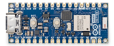
Figure 1: The Arduino Nano Matter Board, featuring the Silicon Labs MGM240S module. (Source: Arduino)
This compact platform enables makers of all experience levels to easily build smart home devices, upgrade existing projects, and experiment with protocols such as Matter, OpenThread, Zigbee, and Bluetooth® Low Energy.
The Silicon Labs MGM240S module at the heart of the Nano Matter board is a system-in-package (SiP) module optimized for battery-powered IoT devices. Built on the Series 2 EFR32MG24 SoC, this module offers advanced connectivity, security, and energy efficiency, making it an excellent choice for smart home and automation applications.
Project Software Overview
The project will use the following software and environments.
- Arduino IDE: Used for writing, editing, and uploading code to the Arduino Nano Matter board
- Amazon Alexa mobile app: Integrated with the project to control the smart blinds via voice commands and routines
- VirtualBox 7.1.2: Used to virtualize the Home Assistant environment on a Windows host
- Home Assistant mobile app: Provides easy access to monitor and control devices
- Home Assistant: Deployed for advanced home automation, enabling flexible local control of IoT devices
- Arduino Cloud: Used to monitor and control devices remotely; provides a cloud-based dashboard for real-time visualization of sensor data; allows integration with IoT applications for remote access and automation
Developing the Project
The goal of this project is to connect an Arduino Nano Matter board to an Amazon Alexa hub via Thread communication, enabling control of roller blinds through the Alexa app. Additionally, you will be able to monitor the blinds via the Arduino Cloud dashboard and Home Assistant app, providing a versatile and flexible control system for smart home automation.
To begin, we’ll review the software needed for development and then move on to the hardware components used in this project.
Setting Up the Arduino IDE
We chose the Arduino IDE for development to ensure full compatibility with the Nano Matter board, which, at the time of development, did not work seamlessly with the Arduino Cloud IDE. The project was broken into stages for easier testing and debugging, starting with basic tests of the board’s Matter capabilities by using pre-built example sketches provided by the Nano Matter library (Figure 2).

Figure 2: Arduino IDE includes many example sketches for Matter. (Source: Mouser Electronics)
To set up the Nano Matter core for development:
- Click File and select Preferences.
- In the Settings tab, in the Additional boards manager URLs field (Figure 3
), enter “https://siliconlabs.github.io/arduino/package_arduinosilabs_index.json” and then click
OK.

Figure 3: Arduino IDE Preferences window. (Source: Mouser Electronics)
- Click Tools, select Board, and then select Boards Manager.
- Search for “Silicon Labs” and install the latest Silicon Labs core (Figure 4).

Figure 4: Silicon Labs core for the Arduino Nano Matter. (Source: Mouser Electronics)
- Click Tools, then click Protocol stack: and select Matter (Figure 5).
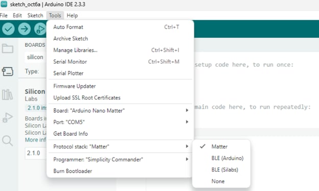
Figure 5: Arduino IDE showing Arduino Nano Matter protocol stacks. (Source: Mouser Electronics)
Setting Up the Arduino Cloud API
Since the Arduino Nano Matter board lacks built-in Wi-Fi® connectivity, we connected to Arduino Cloud via the Matter protocol using Home Assistant for automation. The integration requires the Arduino Cloud application programming interface (API), which is available with a paid subscription. Ensure your subscription plan includes API support for device connectivity.
- In the Arduino Cloud (Figure 6), set up a new Thing with three variables: one to receive data from the temperature sensor, one for the luminosity sensor, and one to track the percentage level of the blinds’ open or closed position (Figure 7).
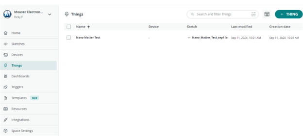
Figure 6: Arduino Cloud dashboard. (Source: Mouser Electronics)

Figure 7: Adding variables in Arduino Cloud. (Source: Mouser Electronics)
- Save the variable IDs (Figure 8), as we will use them later in this project.
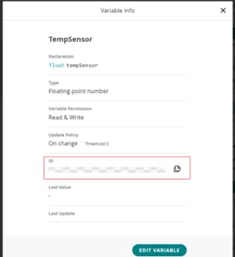
Figure 8: Arduino Cloud showing a variable's ID. (Source: Mouser Electronics)
- Click Space Settings in the left menu and copy your Space ID for future use (Figure 9).
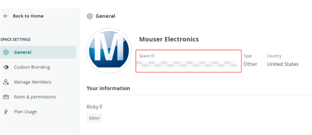
Figure 9: Space Settings and a Space ID in Arduino Cloud. (Source: Mouser Electronics)
- Click your account profile logo in the top-left corner, then select API Keys.
- Create a new API key and securely save it for later use (Figure 10).

Figure 10: Finding API keys in Arduino Cloud. (Source: Mouser Electronics)
Setting Up Home Assistant
This section provides a step-by-step guide to installing Home Assistant using VirtualBox on a Windows machine.
Download Home Assistant VM Image
- On the Home Assistant website, navigate to the Getting Started menu, click Installation, and select Install Home Assistant on Windows (Figure 11).
- Click the View Tutorial button.
- Download the VirtualBox (.vdi) image.
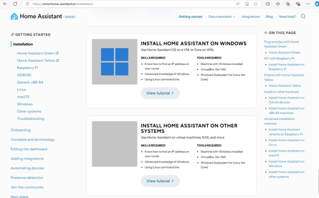
Figure 11: Home Assistant website showing where to obtain a .vdi image for Windows. (Source: Mouser Electronics)
Download and Install VirtualBox
- On the VirtualBox website, click Download or select the Windows Hosts platform package to download VirtualBox.
- Open the installer and follow the prompts to install VirtualBox on your machine.
While VirtualBox installs, locate and extract the downloaded Home Assistant .vdi image file.
Create a New Virtual Machine in VirtualBox
- Open VirtualBox and click New to create a new virtual machine (VM).
- In the Name field, enter “Home Assistant.”
- Set Type to Linux, set Version to Other Linux (64-bit), and then click Next (Figure 12).
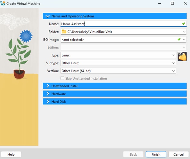
Figure 12: VirtualBox settings for creating a VM. (Source: Mouser Electronics)
Configure VM Settings
- Set the amount of memory (RAM) and number of CPUs. The recommended settings are at least 2GB of RAM and two virtual CPUs.
- Select the Enable EFI This setting is critical for loading Home Assistant (Figure 13).
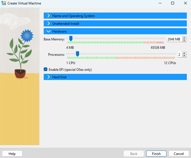
Figure 13: VirtualBox settings for allocating memory and number of processors for a VM. (Source: Mouser Electronics)
Add the Home Assistant Virtual Hard Disk
- Under Hard Disk, select the Use an existing virtual hard disk file checkbox, and then click the folder icon (Figure 14).
- In the next window, click the Add icon at the top left, then browse to the extracted Home Assistant .vdi file.
- Select the file, click Choose, then click Next.
- Click Finish.
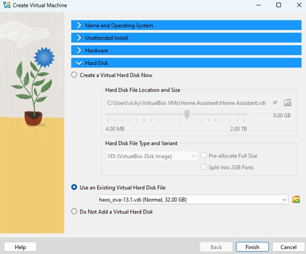
Figure 14: Loading the Home Assistant .vdi file into VirtualBox. (Source: Mouser Electronics)
Configure Network Settings
- Open the VM’s settings and click the Network tab.
- Under Adapter 1, select Bridged Adapter and then select your network adapter from the dropdown menu (Figure 15).
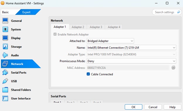
Figure 15: Adding a network adapter in the VirtualBox settings. If the network adapter is set incorrectly, Home Assistant will not communicate with the internet. (Source: Mouser Electronics)
- Click the Audio tab, select Intel HD Audio as the controller, and then click OK.
Start the VM
Now that you have configured the VM and network settings, click Start to launch the Home Assistant VM, watching the boot process until it is complete (Figure 16).
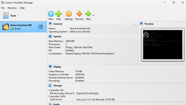
Figure 16: VM as it appears in VirtualBox. (Source: Mouser Electronics)
Complete the Home Assistant Setup
Once the VM is running, open your browser and navigate to http://homeassistant.local:8123.
If necessary, use the VM’s IPv4 address (Figure 17).
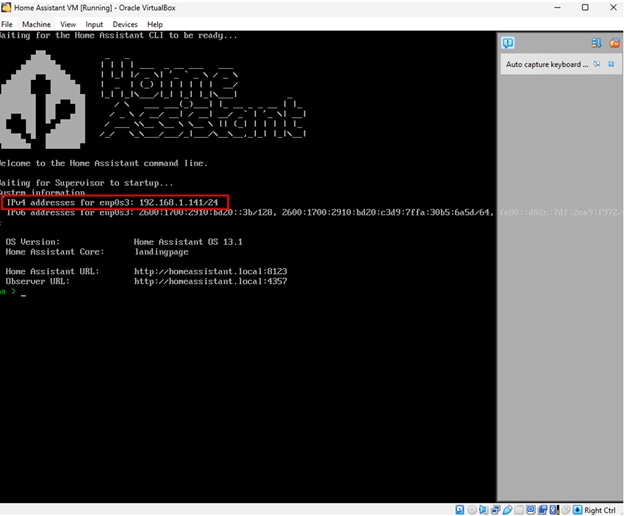
Figure 17: Home Assistant running on a VM. We used the IPv4 address to access Home Assistant remotely. (Source: Mouser Electronics)
- On the Home Assistant welcome screen, click Create My Smart Home to open the setup wizard (Figure 18).
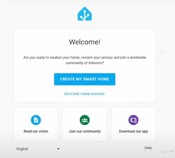
Figure 18: Home Assistant welcome screen. (Source: Mouser Electronics)
- After you complete the setup wizard, the Home Assistant dashboard will appear (Figure 19).
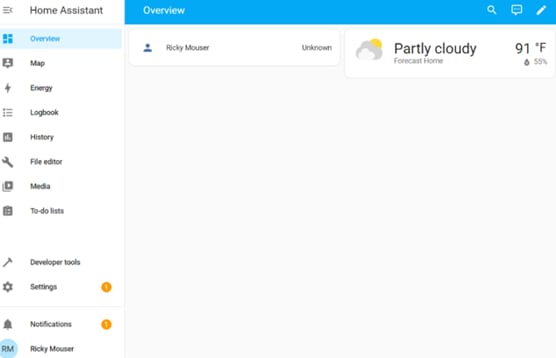
Figure 19: Home Assistant dashboard. (Source: Mouser Electronics)
Powering the Nano Matter Board
The Nano Matter board can be powered either by a USB Type-C cable or an external 5V power supply connected to the IN5V pin. Refer to the board’s pinout in the Project Materials and Resources.
Setting Up the Stepper Motor and TMC2209 Driver
For this project, we used an Analog Devices TMC2209 stepper motor driver, which offers silent operation, high precision, and smooth control—ideal for our smart blinds system. Below is a detailed explanation of how to set up the stepper motor and driver, along with important considerations to ensure optimal performance and prevent damage.
- Connect the motor wires to the TMC2209 driver’s A1, A2, B1, and B2 pins. If you are unsure of the wiring order, use a multimeter to check continuity between motor wires. If two wires are paired (i.e., continuity is detected), connect them to the A1/A2 or B1/B2 pins on the driver (Figure 20).
Note: Incorrect wiring can cause the motor to vibrate without rotating or not function at all.
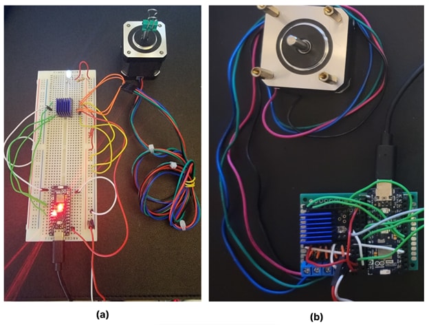
Figure 20: (a) Testing a stepper motor with a TMC2209 driver and an Arduino Nano Matter board on a breadboard setup. (b) Soldered board integrating the motor driver and Arduino Nano Matter. (Source: Mouser Electronics)
Because we are using a 12V power supply to power the stepper motor, make sure the 5V input for the internal logic of the TMC2209 driver is properly connected to the board for smooth motor operation.
- Turn off power to the driver. Once power is off, twist the driver's potentiometer counterclockwise to increase the current or clockwise to decrease the current.
- After you have adjusted the current, power the driver back on and measure the reference voltage to ensure the correct setting. Measuring this voltage gives you a precise, repeatable, and safe way to set the motor current, making it more reliable than adjusting by intuition alone.
The TMC2209 driver can generate heat during operation, so proper heat management is crucial. Attach a heat sink to the driver, ensuring it is placed with sufficient clearance to avoid short circuits with nearby pins. Consider using a cooling fan if needed to prevent overheating and ensure the driver’s optimal performance.
Important Setup Notes:
- Always double-check the driver’s orientation during installation. Incorrect installation can cause permanent damage.
- Never connect the motor while measuring the voltage, as this could burn out the driver.
- During setup and testing, use the main power supply for voltage measurement rather than relying on USB power.
Project Overview
Figure 21 shows the schematic of this project.
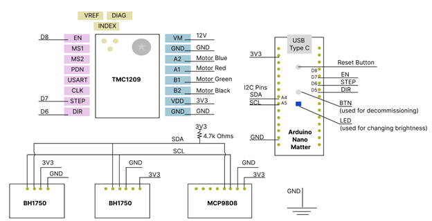
Figure 21: Schematic of the hardware used on this project. (Source: Mouser Electronics)
Arduino Sketch
The final sketch for this project is available on Mouser's GitHub and includes explanations of its key functions and variables. After downloading the sketch, connect the Arduino Nano Matter board to your computer via USB. Ensure the correct board and port are still selected in the Arduino IDE, then click Upload to transfer the code to the board.
The following section explains the sketch's key functions and variables.
Libraries
#include <Matter.h>
#include <MatterWindowCovering.h>
#include <MatterTemperature.h>
#include <TMCStepper.h>
#include <Wire.h>
#include <BH1750.h>
#include <MatterIlluminance.h>
#include <Adafruit_MCP9808.h>
#include <Adafruit_VL53L0X.h>
- Matter and MatterWindowCovering: These libraries handle the Matter protocol, which is used to communicate with smart home devices like Alexa and Thread networks.
- TMCStepper: A library for controlling TMC2209 stepper motor drivers using universal asynchronous receiver/transmitter (UART) communication.
- Wire: Handles I²C communication protocol between the microcontroller and I²C devices.
- BH1750 and MatterIlluminance: BH1750 is a light sensor, and MatterIlluminance facilitates its integration into the Matter ecosystem.
- Adafruit_MCP9808 and MatterTemperature: MCP9808 is a digital temperature sensor, and MatterTemperature integrates its readings with Matter.
- Adafruit_VL53L0X: A library to control the VL53L0X proximity sensor.
Sensor Object Initialization
Adafruit_VL53L0X lox = Adafruit_VL53L0X();
BH1750 lightMeter;
Adafruit_MCP9808 tempsensor = Adafruit_MCP9808();
MatterIlluminance matter_illuminance_sensor;
MatterTemperature matter_temperature_sensor;
- VL53L0X: An object to manage the proximity sensor. We use this sensor to initialize the height of the window.
- BH1750 (lightMeter): An object for light level measurement.
- MCP9808 (tempsensor): This is for temperature sensing. It reads temperature values from the MCP9808 sensor.
- MatterIlluminance and MatterTemperature: Objects to report light and temperature levels to the Matter ecosystem (e.g., Alexa).
Threshold Definitions
const float lightCloseThreshold = 1000.0;
const float lightOpenThreshold = 5.0;
Defines the light intensity (in lux) for closing and opening the blinds. If the light exceeds 1000 lux, the blinds close; if it is below 5 lux, they open.
Pin Definitions and Stepper Motor Setup
#define EN_PIN 7
#define DIR_PIN 4
#define STEP_PIN 3
#define R_SENSE 0.11
#define UART_ADDRESS 0x00
- EN_PIN, DIR_PIN, STEP_PIN: These are the pins used to control the TMC2209 motor driver.
- R_SENSE: The sense resistor value (typically 0.11Ω) needed to configure the motor driver’s current measurement.
- UART_ADDRESS: Used to define the UART address for communication between the microcontroller and the TMC2209.
Stepper Motor Object
TMC2209Stepper driver(&Serial1, R_SENSE, UART_ADDRESS);
Creates a driver object for the TMC2209 stepper motor using UART (Serial1), allowing communication with the motor driver.
Setup Function
void setup() { ... }
- Serial Communication: Serial.begin(115200) initializes the serial communication, and Serial1.begin(115200) is used for UART communication with the TMC2209.
- VL53L0X Sensor Initialization: lox.begin(0x29) initializes the proximity sensor at its default I2C address (0x29).
- Light and Temperature Sensor Initialization: The matter_illuminance_sensor.begin() and matter_temperature_sensor.begin() functions initialize these sensors for Matter reporting.
- TMC2209 Setup:
- driver.begin() starts the motor driver.
- driver.toff(5) sets the off-time for the stepper motor driver to 5.
- driver.rms_current(500) configures the motor to limit its current to 500mA. Depending on the driver you use, the max current might need to be set manually.
- driver.microsteps(1) ensures the motor runs at full step.
- driver.en_spreadCycle(false) enables the quiet mode called StealthChop for smoother, silent operation.
- LED and Pin Setup: pinMode() functions set the direction for specific pins, such as the built-in LED and motor control pins (STEP, DIR, EN).
Loop Function
void loop() { ... }
- Light and temperature reporting:
- float lux = lightMeter.readLightLevel() reads the ambient light level.
- float tempC = tempsensor.readTempC() reads the current temperature in Celsius.
- matter_illuminance_sensor.set_measured_value_lux(lux) and matter_temperature_sensor.set_measured_value_celsius(tempC) report the light and temperature levels to Matter.
- Motor control:
- The motor’s position is continuously updated using the matter_blinds.get_requested_lift_position_raw() and set_actual_lift_position_raw() functions.
- The blinds’ position (up or down) is adjusted based on light levels using the check_light_and_adjust_blinds() function.
Light Control Logic (Blinds)
void check_light_and_adjust_blinds (int32_t current_percent) { ... }
- Lux Threshold Check: If the light level is above the high threshold (1000 lux), the blinds will close. If the light is below the low threshold (5 lux), they will open. We decided to implement this automation with code since the Alexa app does not currently support creating routines with light sensors.
- Blinds Movement: The move_blinds() function adjusts the blinds’ position as either up or down.
Motor Movement Functions
void step_motor() { ... }
void stop_motor() { ... }
- step_motor(): Controls the motor to take one step by toggling the STEP_PIN and adjusting the pulse width for speed control.
- stop_motor(): Stops the motor by disabling the motor driver and halting pulses to the STEP_PIN.
Decommission Handler
void decommission_handler() { ... }
This function checks if the built-in button is pressed for more than 10 seconds, initiating decommissioning of the device from Matter by erasing stored data.
LED Brightness Update
void update_onboard_led(uint8_t brightness) { ... }
This adjusts the onboard LED brightness based on the position of the blinds. If the blinds are closed, the brightness will be zero; if fully open, it will map the brightness between 10 and 255.
Integrating Amazon Alexa
To integrate the Arduino Nano Matter board with Amazon Alexa, follow these steps:
- After uploading the sketch to the Arduino Nano Matter board, a QR code URL will appear in the Serial Monitor (Figure 22).
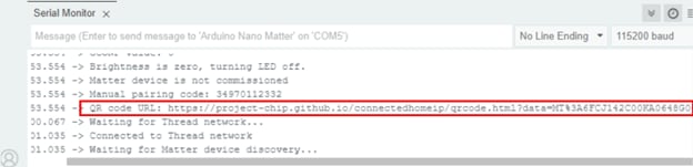
Figure 22: Arduino IDE showing the URL for the QR code required for commissioning. (Source: Mouser Electronics)
- Copy and paste the URL into your browser to access the QR code.
- Open the Amazon Alexa app and click the + symbol in the upper right corner.
- Select Device, then select the Matter logo.
- Scan the QR code generated by the Nano Matter sketch using the Alexa app.
- Select the available Thread network and wait for the device to be commissioned and added to the Alexa app (Figure 23).
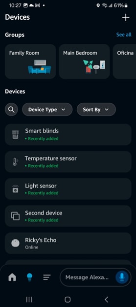
Figure 23: Amazon Alexa showing the smart blinds and light and temperature sensors. (Source: Mouser Electronics)
Your Matter-compatible device will now be integrated and ready for use in the Alexa app.
Note: If you encounter any problems connecting your Arduino Nano Matter board to the Alexa app, follow our debugging tips. Figure 24 shows some of the problems we encountered during this implementation.

Figure 24: These are some of the errors we encountered when connecting the Arduino Nano Matter to the Alexa App. If you encounter similar issues, try the debugging tips available on the Mouser GitHub. (Source: Mouser Electronics)
Integrating Home Assistant & Arduino Cloud
In this section, we will integrate the Arduino Nano Matter board with Home Assistant and forward sensor data to the Arduino Cloud for monitoring via the Arduino API.
Setting Up Home Assistant and Adding Devices
To configure Home Assistant for managing Matter devices, install the Matter Server add-on:
- Open the Home Assistant Settings menu (Figure 25).
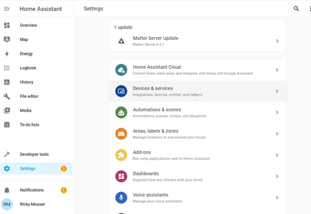
Figure 25: Home Assistant settings menu. (Source: Mouser Electronics)
- Click Add-Ons, then click Add-On Store.
- In the search field, enter “Matter Server.”
- Locate the Matter Server add-on in the results and click Install.
- Install the File editor add-on, as it is required in later steps.
- Once you have installed the add-ons (Figure 26), ensure they are properly configured and running to enable Matter device management within Home Assistant.
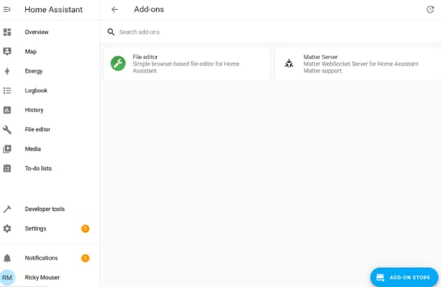
Figure 26: File editor and Matter Server Home Assistant add-ons. (Source: Mouser Electronics)
Next, install the Home Assistant app on your smartphone and log into your account. Then add your sensors to Home Assistant:
- In the Alexa app, select Control device with another assistant or app (Figure 27).
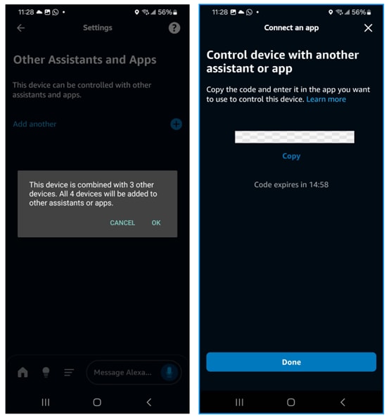
Figure 27: Amazon Alexa app settings for adding another assistant or app to control devices. (Source: Mouser Electronics)
- In the Add Matter Device window, select Yes, it’s already in use.
- Select Other controllers, then copy the setup code provided.
- In the Home Assistant app, navigate to Add Matter Device and paste the setup code (Figure 28).
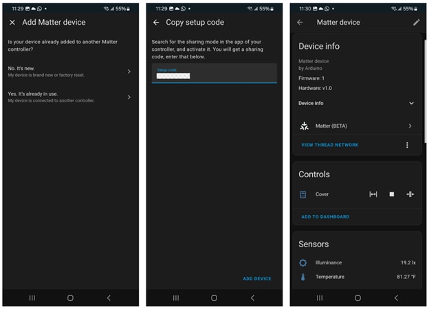
Figure 28: Adding Matter devices to Home Assistant using the pairing code copied from the Alexa app. (Source: Mouser Electronics)
Once the devices are integrated, the Home Assistant dashboard should display data from your temperature sensor and luminosity sensor as well as a control icon for the blinds (Figure 29).
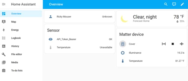
Figure 29: Home Assistant web app showing connected Matter devices (Right). (Source: Mouser Electronics)
Configuring Arduino Cloud Integration in Home Assistant
Open the File editor add-on from the left menu, then locate secrets.yaml in the directory (Figure 30). If the file doesn’t exist, create it. This file securely stores sensitive data like project IDs, credentials, and API keys, keeping your main configuration files clean and protected.

Figure 30: Home Assistant File editor. Click Browse Filesystem to select the file you want to edit. (Source: Mouser Electronics)
In the secrets.yaml file, add the following configuration, replacing placeholders with your Space ID, Client ID, Client Secret, and Thing ID:
arduino_organization: <Space ID>
token_get_payload: '{"grant_type":"client_credentials","client_id":"
arduino_temp_url: https://api2.arduino.cc/iot/v2/things/
Next, create a RESTful integration:
- In the File editor add-on (Figure 31), open the configuration.yaml file and define the RESTful integration to generate an API token for Arduino Cloud:
rest:
- resource: "https://api2.arduino.cc/iot/v1/clients/token"
scan_interval: 240 #4 min
timeout: 60
method: "POST"
headers:
content_type: 'application/json,application/x-www-form-urlencoded'
payload: !secret token_get_payload
sensor:
- name: "API_Token_Bearer"
value_template: "OK"
json_attributes_path: '$..'
json_attributes:
- 'access_token'
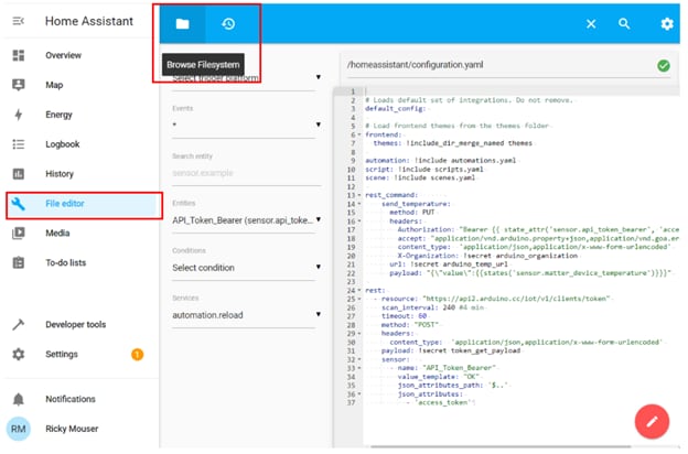
Figure 31: Home Assistant File editor showing the configuration.yaml file. (Source: Mouser Electronics)
- Define the RESTful command to send data to Arduino Cloud by adding the following code to the configuration.yaml file and save your changes.
rest_command:
send_temperature:
method: PUT
url: !secret arduino_temp_url # URL for temperature sensor
headers:
Authorization: "Bearer {{ state_attr('sensor.api_token_bearer', 'access_token') }}"
accept: "application/vnd.arduino.property+json,application/vnd.goa.error+json"
content_type: 'application/json,application/x-www-form-urlencoded'
X-Organization: !secret arduino_organization
payload: "{\"value\":{{states('sensor.matter_device_temperature_2')}}}"
send_light_level: # New sensor (e.g., light level sensor BH1750)
method: PUT
url: !secret arduino_light_url # Add URL for light sensor
headers:
Authorization: "Bearer {{ state_attr('sensor.api_token_bearer', 'access_token') }}"
accept: "application/vnd.arduino.property+json,application/vnd.goa.error+json"
content_type: 'application/json,application/x-www-form-urlencoded'
X-Organization: !secret arduino_organization
payload: "{\"value\":{{states('sensor.matter_device_illuminance')}}}"
send_blind_percent: # Percentage of blind open/close
method: PUT
url: !secret arduino_blind_url # Add URL for blind level
headers:
Authorization: "Bearer {{ state_attr('sensor.api_token_bearer', 'access_token') }}"
accept: "application/vnd.arduino.property+json,application/vnd.goa.error+json"
content_type: 'application/json,application/x-www-form-urlencoded'
X-Organization: !secret arduino_organization
# payload: "{\"value\":{{states('cover.matter_device_cover')}}}"
payload: "{\"value\":{{state_attr('cover.matter_device_cover', 'current_position')}}}" # Referencing the position attribute of the cover
Note that each device has specific attributes; for the blinds, we used the current_position attribute to send data to Arduino Cloud. To locate this attribute, go to Developer tools in the left menu, and click the States tab (Figure 32).
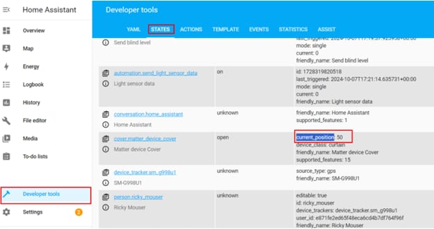
Figure 32: Home Assistant Developer tools showing the states and attributes of our Matter devices. (Source: Mouser Electronics)
- While still in Developer Tools, click the YAML tab.
- Click Check Configuration to ensure there are no errors in the YAML configuration.
- If no errors are found, click Restart (Figure 33).
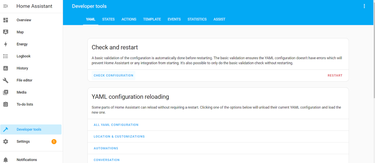
Figure 33: If no errors are found in your code edits, restart your Home Assistant server. (Source: Mouser Electronics)
Creating Automations in Home Assistant
Next, we will set up automation for temperature updates.
- Open the Settings menu and select Automations & scenes (Figure 34).
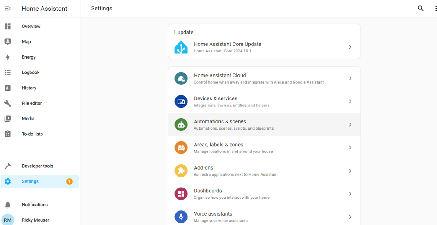
Figure 34: Home Assistant Settings for adding and editing automations. (Source: Mouser Electronics)
- In the Create automation window, click Create new automation (Figure 35).
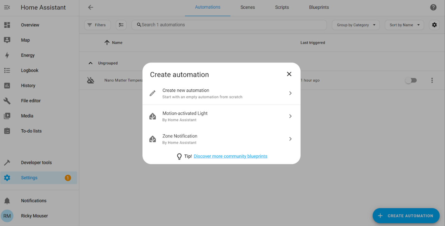
Figure 35: Adding a new automation in Home Assistant. (Source: Mouser Electronics)
- Click the three dots in the top-right corner and select Edit in YAML (Figure 36).
- Paste the following YAML code.
alias: Nano Matter Temperature
description: ""
trigger:
- platform: state
entity_id:
- sensor.matter_device_temperature_2
condition: []
action:
- data: {}
action: rest_command.send_temperature
mode: single
alias: Send blind level
description: ""
trigger:
- platform: state
entity_id:
- cover.matter_device_cover
condition: []
action:
- data: {}
action: rest_command.send_blind_percent
mode: single
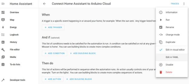
Figure 36: Editing automations in Home Assistant. (Source: Mouser Electronics)
- Once the automation is in place, the sensor data from your Nano Matter board will be automatically forwarded to the Arduino Cloud whenever the sensor detects a change.
Monitoring Data in Arduino Cloud
To monitor sensor data in Arduino Cloud, you must first create a dashboard:
- Log in to your Arduino Cloud account.
- Click Dashboards and create a new dashboard using the available widgets.
- Add a widget for the temperature sensor and other data points (i.e., luminosity, blinds control) to monitor data from the Nano Matter board (Figure 37). Don’t forget to link your widgets to the variables created in the Setting Up the Arduino Cloud API section of this project.
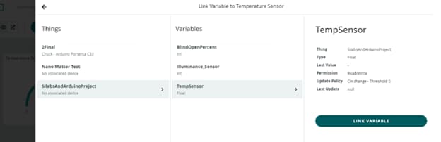
Figure 37: Arduino Cloud dashboard for adding and linking variables to gadgets. (Source: Mouser Electronics)
Adding Alexa Routines
As mentioned, the Alexa app does not currently support routines based on light sensor data. To address this, we programmed the control logic in Arduino to automatically close the blinds when the light level reaches a certain threshold. However, at the time of writing, Alexa supports routines triggered by data from temperature, motion, contact, and humidity sensors.
For this proof of concept, we set up an Alexa routine based on temperature, closing the blinds at 85°F and opening them at 70°F.
- Launch the Amazon Alexa app on your smartphone or tablet.
- Tap the More icon (three horizontal lines) in the bottom-right corner and select Routines.
- Tap the + icon in the top-right corner to create a new routine.
- Name the Routine, giving it a descriptive name such as “Close Blinds at High Temperature.”
- Set a Trigger by tapping When this happens, and then selecting Smart Home.
- Choose the temperature sensor for the room you’re monitoring.
- Set the trigger condition to “Temperature is above 85°F,” and tap Save.
- Tap Add Action, then select Smart Home.
- Choose the smart blinds you want to control.
- Set the action to Close (or Lower, depending on the blinds’ options).
- Tap Finish to finalize the routine.
To create a routine to automatically open the blinds when the temperature drops to 70°F (Figure 38).
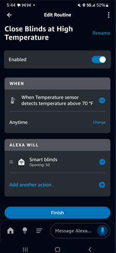
Figure 38: Amazon Alexa Routines editing screen. (Source: Mouser Electronics)
After creating both routines, test them by manually adjusting the temperature sensor or waiting for actual room temperature changes. Ensure the blinds respond appropriately to the programmed temperature triggers.
Putting It All Together
In this project, we successfully implemented a fully integrated smart roller blind system that leverages multiple platforms for control and monitoring. We began by setting up control through the Alexa app using an Echo (4th Gen) as the central hub, allowing us to create automated routines for the blinds based on room temperature. From there, we integrated the system with Home Assistant, enabling more advanced, localized automation options without relying on external cloud services. This provided flexibility in managing and automating various components of the system, including sensors for temperature and luminosity (Figure 39).
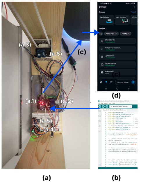
Figure 39: The completed project build, showing (a) hardware used in this project—(a.1) Arduino Nano Matter, (a.2) motor driver, (a.3) stepper motor, (a.4) luminosity sensor, (a.5) temperature sensor, and (a.6) distance sensor—(b) Arduino IDE with our code, (c) Amazon Echo 4th Gen, and (d) Amazon Alexa app with our Matter devices. (Source: Mouser Electronics)
To complete the setup, we forwarded the sensor data to the Arduino Cloud, where we built a real-time dashboard to visualize and monitor the sensor data. By combining Alexa, Home Assistant, and Arduino Cloud, we created a robust, multi-platform automation system that offers seamless smart home integration and real-time monitoring and control. This project not only demonstrates how to design and build a Matter-powered smart home system but also highlights the flexibility of using multiple platforms to maximize functionality and control (Figure 40).
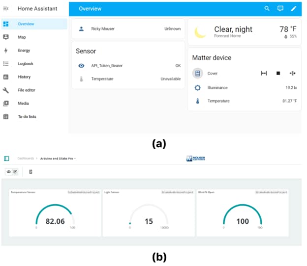
Figure 40: (a) Home Assistant dashboard showing our connected matter devices, (b) Arduino Cloud dashboard showing the connected Matter devices. (Source: Mouser Electronics)
Taking It a Step Further
There are several ways to enhance the current smart blinds system, making it more versatile and efficient.
Distance Sensor
Improve the DFRobot SEN0245 distance sensor by adding a dedicated button that recalibrates the blinds’ height for different window sizes This eliminates the need to press the reset button on the Arduino board, which currently reinitializes the entire sketch.
Luminosity Sensor
The Adafruit BH1750 light sensor’s sensitivity to minor ambient light changes, combined with continuous lux level checks in the loop, can cause unnecessary and frequent blind adjustments, leading to motor wear and system inefficiency. Implementing the following solutions may solve this problem.
Debounce/Deadband
To avoid frequent changes due to minor fluctuations, introduce a debounce period in which the system waits for a stable light condition within a threshold for a certain period before moving the blinds. Additionally, implementing a deadband around the lux threshold values (e.g., only act if the lux is outside a ±10 lux range) can help avoid unnecessary frequent movements.
The following code implements a debounce and deadband optimization:
const float lightDebounceTime = 5000; // 5 seconds debounce period
const float deadband = 50.0; // Lux deadband to avoid minor fluctuations
unsigned long lastLightCheck = 0; // To track the last time light was checked
void check_light_and_adjust_blinds(int32_t current_percent) {
float lux = lightMeter.readLightLevel(); // Get light level in lux
unsigned long currentTime = millis();
// Only check if the last check was more than the debounce time ago
if (currentTime - lastLightCheck > lightDebounceTime) {
lastLightCheck = currentTime; // Reset debounce timer
Serial.print("Current light level: ");
Serial.print(lux);
Serial.println(" lx");
// **Close blinds only if light exceeds threshold beyond deadband**
if (lux > (lightCloseThreshold + deadband) && current_percent < 100) {
Serial.println("Light is too bright! Closing blinds automatically...");
move_blinds(current_percent, 100); // Close blinds fully
}
// **Open blinds only if light is below threshold beyond deadband**
else if (lux < (lightOpenThreshold - deadband) && current_percent > 0) {
Serial.println("Light is too low! Opening blinds automatically...");
move_blinds(current_percent, 0); // Open blinds fully
}
}
}
Feedback System
Incorporate a feedback system using a potentiometer or an encoder to track the exact position of the blinds. This will allow the system to always know the precise position of the blinds, reducing the chance of overshooting or undershooting. Using an encoder with the motor also provides precise movement control, ensuring the system moves only as much as needed without relying solely on lux readings.
Limit Switches
Add limit switches at the fully open and fully closed positions to provide additional safety and control. The system can use these to prevent the motor from trying to move beyond the physical limits of the blinds, which could cause damage. The limit switches could also serve as a reference for resetting the blinds' position if the system loses track of the position (e.g., after a power failure or manual adjustment).
Averaging or Smoothing Sensor Readings
To combat minor lux fluctuations, have the system average the last few sensor readings (e.g., every five readings) before deciding to open or close the blinds. This can help eliminate the effects of temporary changes in light conditions.
Compact Design and Prototyping
Refine the design using a compact, 3D-printed housing that integrates all the components. Additionally, the gears for controlling the blinds can also be improved and 3D printed, allowing for easy adjustments during development.
Expanded Automation and Routines
Create additional routines to control multiple devices, enabling the system to interact with other smart home components, such as lights, thermostats, or security systems. The code can also be enhanced to include RGB lights for an appealing lighting effect.
Voice Control and Advanced Automation
Integrate voice control using platforms like If This Then That (IFTTT) or Home Assistant, enabling users to control the blinds via simple voice commands. The blinds can also be automated based on real-time weather data.
Energy Efficiency and Manual Control
Add a solar panel to charge a battery during the day, making the setup more energy-efficient and reducing reliance on external power sources. For added convenience, include a capacitive sensor to provide manual control over the blinds.
Security System Integration
Integrate the smart blinds with the home’s security system, allowing them to close or open based on alarm activation.
Feedback Sensors for Precision
Incorporate feedback sensors such as limit switches or encoders to help monitor the exact position of the blinds. This will provide more accurate control and ensure the blinds are positioned correctly.
By implementing these enhancements, you can make the smart blinds system more adaptive, energy-efficient, and fully integrated with other smart home technologies, providing users with greater control and convenience.
Conclusion
This project demonstrates the powerful potential of the Matter protocol in building a connected smart home system. Using the Arduino Nano Matter board with onboard Silicon Labs MGM240S module, a variety of sensors, and Alexa, we created a seamless, secure, and scalable solution that integrates multiple devices using Thread and Bluetooth Low Energy. The Matter protocol simplifies the commissioning process, ensures robust security, and promotes interoperability across devices, making it the future of smart home automation. The flexibility of the Arduino Nano Matter board allows engineers and developers to easily prototype and expand their IoT systems, with endless possibilities for adding new Matter-compatible devices. This project serves as a solid foundation for future enhancements, offering the potential for more complex and creative smart home integrations.