Electronic Systems for Space Require a Fail-Safe Design

Image Source: Boris Rabtsevich/Shutterstock.com
By Adam Taylor for Mouser Electronics
Published August 10, 2021
Electronic systems are ubiquitous in modern life, and most people carry at least one nearly everywhere they go in their cellphone. Electronic systems enable us to communicate, navigate and interact with the world safely while also enabling us to explore space and the universe.
Of course, when electronic systems are designed for applications where life could be endangered or environmental damage could occur, these systems need to be designed to ensure they fail safely in case a failure or unexpected event occurs.
Designing electronic systems for high reliability and mission-critical systems requires the developer to consider the desired functionality, the failure conditions, and the environment in which the equipment must operate. To help designers ensure that electronic systems are suitable for use in these demanding applications, several internationally recognized standards guide engineers in achieving the necessary certification standard. The most common of these standards are IEC61508 (industrial applications), ISO26262 (automotive), and DO178 & DO254 (airborne systems). Although each approach is slightly different, each has several certification levels, indicating the reliability of the equipment as outlined in Figure 1 for IEC61508.
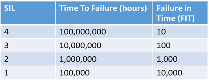
Figure 1: Safety Integrity Level (SIL) as defined by IEC61508 for a continuous demand system (Source: Author)
These standards take into account the design and design analysis and the development processes and even the suitability of the tool chains used.
For most high-reliability and mission-critical systems, the operating environment can play a significant part in the equipment’s design. Temperature extremes can result in increased power dissipation at high temperatures, potentially compounding challenging thermal design requirements. In contrast, low temperatures can result in start-up issues and increased currents during power on. Of course, the propagation delay of circuits also changes with temperature, so high-reliability systems must ensure timing closure at both temperature extremes and a little beyond to provide sufficient margin. In addition to being able to survive and operate across temperature extremes, electronics must also be able to survive dynamic environments that introduce sinusoidal/random vibration that can be caused by motors or pumps in the equipment (sinusoidal) or from turbulence or interaction with the road surface (random). We also need to develop equipment that can survive short-duration high-acceleration events—or shock, as it is more commonly known. Shock can happen when the equipment is dropped, so the design must survive both vibration and shock. Designing to survive temperature, vibration, and shock requires a multidisciplinary approach with electronic designers and mechanical/thermal designers. This collaboration ensures that heat dissipation is optimized to achieve component derating at high-temperature operation, and the mechanical design is sufficiently braced and analyzed to support the vibration and shock environment. However, it is not just physical failure that might occur because of temperature, vibration, and shock. It can also lead to temporary or permanent failure in the device if, for example, bond wires inside devices create a glitch.
For some systems, such as an aircraft, we must also consider radiation, including terrestrial radiation in the form of single-event upsets. The single-event effect (SEE) rate can be significant depending upon the altitude and latitude of the operation. SEE can cause transients on signal lines or flip the state of data stored in memories or registers. If the end application is in space, SEE can be more significant for the transients and bit flips, including destructive effects on the device. In addition to the SEE, ionizing radiation will also change the device’s behavior over time, including increasing power dissipation and changing propagation delays. Modeling the radiation environment enables the designers to understand the SEE rate and ionizing dose for the operating environment.
One of the key elements of design for mission-critical and high-reliability systems is defensive design. As such, the electronic system is designed to either avoid or tolerate failures, the interrelationship between hardware (HW), software (SW) faults, and tolerance is demonstrated in Figure 2.
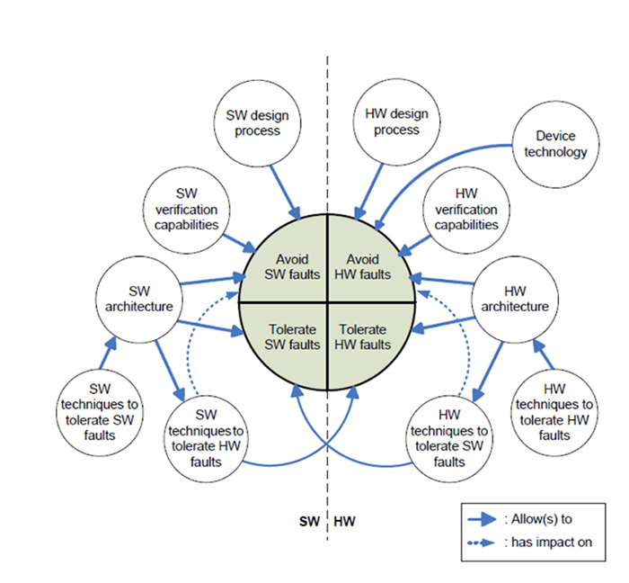
Figure 2: Hardware and Software Fault Tolerance and Avoidance (Source: Author)
Avoidance schemes include the designer selecting higher quality components suitable for the environment, for example, industrial or automotive. Also, analysis techniques such as part-stress analysis, worse-case analysis, failure-mode effects, and criticality analysis can be performed to identify areas of concern in the design to be addressed early in the design process.
Tolerance ensures that the design can continue to operate if an error or failure occurs during operation. The system needs to detect the failure, localize the failed element, isolate the failure to limit propagation, and reconfigure the system to recover from failure if possible. Implementing tolerance within the design requires considerable analysis and self-test capabilities. The goal with tolerance is to prevent a single point failure from affecting redundant elements of the design, thereby ensuring that one failure does not prevent the system from continuing to function or failing safely.
Design techniques that can be used to ensure tolerance include:
- Introduction of redundancy and hardware fault tolerance.
- Use of error detection and correction codes to protect and detect corruption in memories.
- Built-in self-test (BIST) that runs at power on, during operation, and on-demand with more detailed tests.
- Robust communication links that leverage hamming distance/arm and fire structures/timeouts and error-correcting codes.
- Triple modular redundancy and voting on the result to give the most probable answer.
- Repetition in time of operations to overcome transient errors.
- Redundant clock and clock detection and switching schemes.
- Power management and monitoring systems to reduce power in the event of a failure to failed circuits.
Of course, developing for mission-critical and high-reliability applications also brings considerable additional design and analysis effort that increase development costs and time scales.
The design techniques focus on the avoidance and tolerance of failures. It is common to use Failure Mode, Effects and Criticality Analysis (FMECA) at the component level to determine the failure mode of the components (open circuit, short circuit, high impedance, etc.) in addition to how that failure is detected in the system and the local and end effects. This FMECA, combined with the part-stress analysis, will also enable calculating the failure rate given in Failures in Time (FIT), where one FIT is 1x10⁻⁹ hours. Knowing the FIT rate for the system enables the mean time between failure to be calculated and the overall probability of success (Figure 3). Of course, knowing the FIT rate also enables us to make sure the system will be compliant with the required safety level, be it safety integrity (SIL)4 or Design Assurance Levels (DAL)-A.
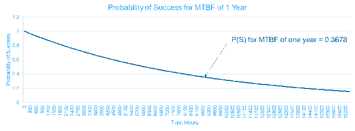
Figure 3: Probability of Success for a one-year operation with an MTBF 8760 Hours (Source: Author)
Conclusion
Designing for mission-critical or high-reliability applications can be one of the most challenging and rewarding developments of an engineer’s career. Although the challenges of ensuring safe and reliable operations across temperature, vibration, shock, and radiation can lead to long hours and much analysis, the final application can be literally out of this world.