Vector Control for BLDC Motors Using Advanced MCUs
Smaller-scale applications can now use this advanced motor-control tech

(Source: Wire_man/stock.adobe.com)
Published June 24, 2026
The ubiquitous use of DC motors is a testament to ongoing technological advances and developments in specialties such as magnetics, materials science, processors, software, and power semiconductors. These motors are embedded in countless household products, from power tools to automobiles. In fact, the average car—whether ICE, hybrid, or electric—contains dozens of DC motors, not including the traction motors in hybrids and electric vehicles (EVs).

Figure 1: Small and medium motors surround us and are embedded in our daily lives. (Source: anantachat/stock.adobe.com)
DC motors come in three basic types: brushed, brushless (BLDC), and stepper. Brushed motors, powered directly from a DC rail, have been used since the late 1800s, and remain popular for their low cost and unique performance characteristics. BLDC motors offer higher efficiency, improved reliability, and greater control than brushed motors and are well-suited for continuous rotation, but they require more complex drive circuitry.
The brushless DC motor offers many operational advantages, but fully realizing these capabilities requires much more than the simple drive circuitry of the brushed motor. As a result, its use has traditionally been limited to applications using smaller fractional-horsepower motors, such as power tools and small appliances.
Among the various methods for controlling BLDC motors, one of the most advanced and widely used techniques is vector control, also known as field-oriented control (FOC). Vector control enables highly precise, efficient, and responsive motor operation, but requires complex algorithms to act on real-time current and voltage information. Now, advances in processors, combined with appropriate support functions, have made vector control a practical approach for BLDC motors in lower-power applications, including power tools, small appliances, and similar compact systems.
This blog examines the fundamentals of BLDC motor operation, breaks down the principles behind FOC, and highlights how modern, integrated motor-control MCUs enable designers to implement high-efficiency, high-precision solutions in compact, smaller-scale applications such as power tools.
Motor Control Basics
The objective of motor control is to determine a motor’s position, speed, and acceleration under fixed (static) and varying (dynamic) load conditions in real time and then adjust the drive currents to maintain the desired setpoints of these performance parameters.
These setpoints are not constant but shift during motor operation. It's the system's higher-level controller task to determine the desired setpoint and the changes to the setpoint. For example, a motor may be instructed to smoothly accelerate from zero revolutions per minute (rpm) to a predefined rpm, run for a period, then stop and hold its position.
The motor driver takes the desired setpoint signal and drives the motor to reach and track it. The parameter to be controlled—position, velocity, or acceleration—depends on the application. The three parameters are related: velocity represents the rate of change of position, while acceleration represents the rate of change of velocity. Therefore, if the system continually knows the rotor position, it can determine the other two factors.
In simple terms, the BLDC motor’s underlying principle is based on three coils spaced 120⁰ apart.
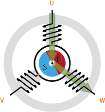
Figure 2: A simplified explanation of the BLDC motor principle of operation uses three coils with 120⁰ spacing that are driven by controlling the phases and coil currents. (Source: Renesas Electronics)
As current is applied to the coils in sequence, the rotor's permanent magnet follows the rotating magnetic field produced by the coils. Although this explanation uses just three coils, real motors usually have six or more coils for smoother operation and high-resolution control, but the principle is the same.
The classic method for implementing current-drive timing is rotor feedback and closed-loop control. A position sensor senses the rotor position and sends a signal back to the controller.
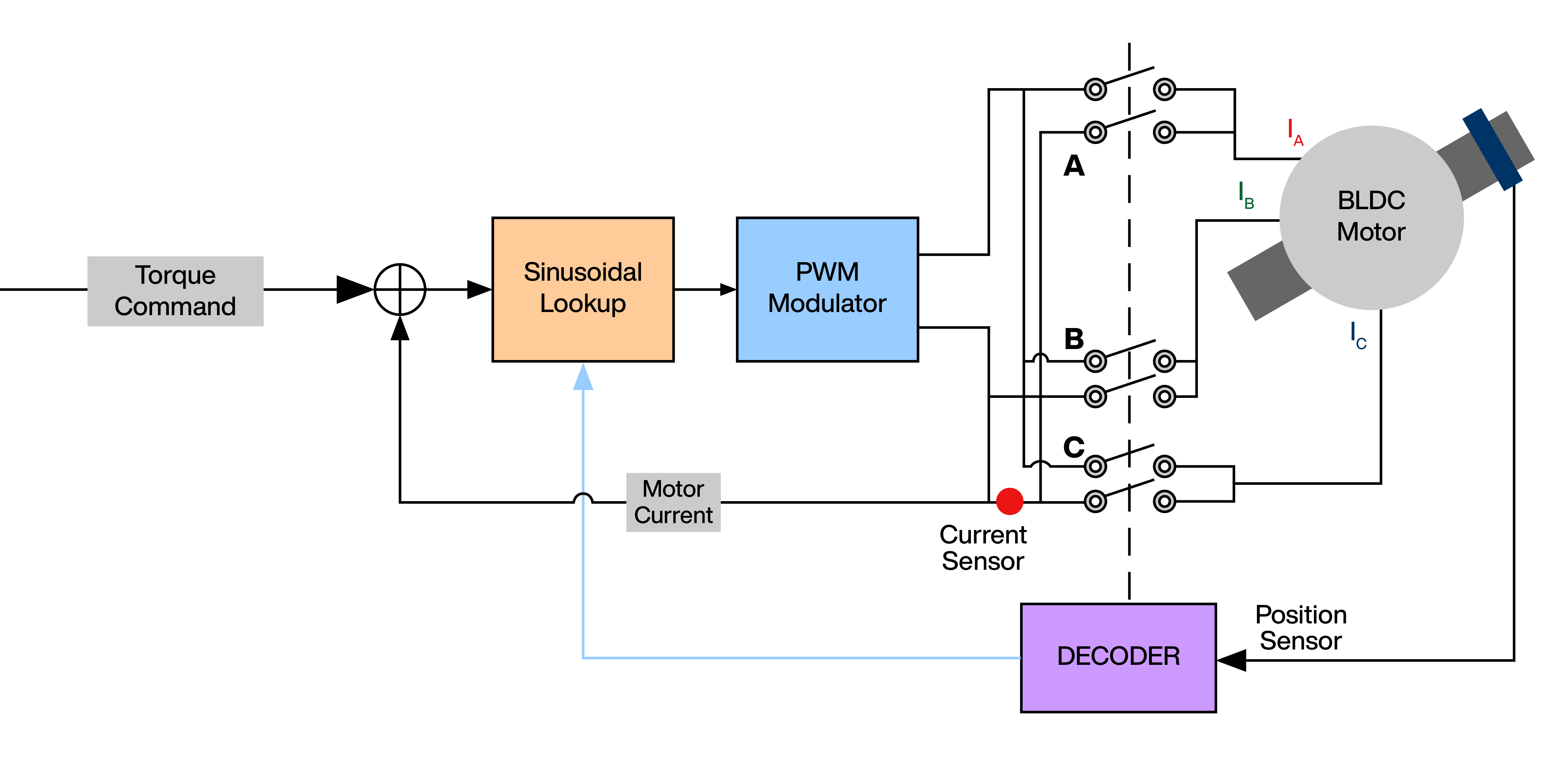
Figure 3: In closed-loop motor control, the rotor position is sensed and fed back to the controller, which then sends a correcting signal to drive the actual position to that setpoint. (Source: Mouser Electronics)
This sensor is typically a Hall-effect device, optical encoder, or resolver. The controller, in turn, adjusts the motor drive current to minimize the error difference between the desired setpoint and the measured value.
A closed-loop algorithm, such as the well-known proportional-integral (PI) approach, is often used as the closed-loop control strategy. The controller that establishes the setpoint often applies additional “corrections” to compensate for real-world effects such as motor and load inertia, motor response characteristics, and desired application-specific velocity and acceleration profiles.
Vector Motor Control Principles
For many years, motor experts have explored the concept of sensorless vector control and its complex mathematical aspects. A major advantage of sensorless vector control is that it can eliminate the need for a physical position sensor in some implementations, thereby reducing costs, space requirements, and the risk of a potential failure point. However, there was a tradeoff: a relatively powerful processor was needed to calculate the matrix math and associated trigonometry that are key to vector control.
Vector control infers rotor position indirectly rather than relying on a physical sensor. The process begins with continuous, real-time measurement of two of the three stator-coil currents using current sensors and analog-to-digital converters (ADCs). In simple terms, the three currents are then resolved into two orthogonal constituents: an in-phase one that is aligned with the rotor poles, and a quadrature one that is perpendicular to the rotor poles and generates torque on the rotor. The motor controller performs complex calculations on the rotor position and speed vectors to drive the currents to the stator coils and so produce the desired rotor torque and speed.
Basic trapezoidal-currentto induce torque ripple during commutation. Trapezoidal commutation does not deliver the smooth, precise control needed for brushless DC motors, especially at low speeds.
Sinusoidal commutation addresses this problem. This control delivers smooth rotation by using three-phase current to control the flux smoothly. Sinusoidal control is more complicated because it must accurately deliver differing amounts of current to all three phases. However, its system-level benefits often outweigh the technical cost.
Despite implementation challenges, vector motor control enables the motor to maintain high torque for power tools under varying load conditions; it also enables higher speeds to meet the demands of specialized motors, such as surgical drills, which can reach 100,000 rpm. Note that in some higher-performance systems, an encoder is used with vector control to cross-check the control loop and simplify motor start-up from a known position; despite this extra cost, vector control still offers significant performance benefits.
Implementing Vector Motor Control
Sensorless vector control takes more than understanding equations and efficient ways to execute them. It requires a focused, application-optimized microcontroller unit (MCU) that is equipped to capture motor current measurements, rapidly solve the trigonometric functions needed to convert coordinate space, and use those results to control the MOSFET power devices. Until recently, the cost in dollars, power, and circuit-board footprint was prohibitive for lower-cost or highly portable applications.
Now, that situation has changed with the availability of devices such as these in the Renesas Electronics RA2T1 64MHz Entry Level Motor Control MCU family. The RA2T1 is part of a scalable family of software- and pin-compatible Arm®-based 32-bit MCUs that share a common set of Renesas peripherals, facilitating design scalability.
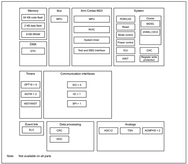
Figure 4: The internal block diagram of the Renesas Motor Control MCU family shows all available internal functions; the specific set depends on the selected model. (Source: Renesas Electronics Corp.)
These MCUs are optimized for BLDC and permanent-magnet synchronous motor (PMSM) control and also integrate the necessary analog peripherals, such as high-speed ADCs, comparators, and timers, to enable precise motor operation. They include up to 64 kilobytes of code flash memory, 2 kilobytes of data flash memory, 8 kilobytes of static RAM, a 12-bit ADC, a high-speed analog comparator, safety features, and numerous other peripheral functions, such as timers.
Programming an MCU for vector control—or any other control—is a challenging task. For this reason, the MCUs are supported by Renesas’ Flexible Software Package, which includes firmware to simplify motor control development using the MCU’s onboard peripherals. This package simplifies development and accelerates time-to-market for motor-driven applications in home appliances, power tools, and industrial automation. It includes configurable tools and automated code generation to streamline programming and debugging.
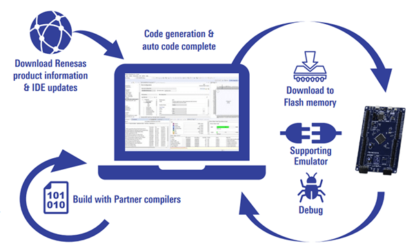
Figure 5: The supporting Flexible Software Package includes the firmware, tools, and other elements needed to bundle an effective motion controller. (Source: Renesas Electronics Corp.)
The comprehensive suite enables designers to tailor system operation to application-specific preferences and profiles precisely. Relevant factors include the characteristics of the motor itself; desired dynamic performance, including ramp-up, ramp-down, acceleration, and deceleration profiles; response to transient load shifts; and tradeoffs between speed and acceleration and positioning precision and overshoots.
It’s important to recognize that applications have different priorities. For example, a power tool may need to maximize torque across its operating range, while a robotic actuator may focus on smooth acceleration and precise stopping.
In addition to the MCU and its firmware, Renesas offers high-performance MOSFETs for powering the stator coils. The Renesas Electronics REXFET-1 100V & 150V Power MOSFETs feature low RDS(ON) values of 1.5mΩ, 2.9mΩ, 3.7mΩ, 6.7mΩ, 11.1mΩ, and 21mΩ, depending on the selected version, thereby improving efficiency at high current levels.
These MOSFETs are designed for exceptional thermal performance for demanding applications. They are available in TO-Leadless (TOLL), TO Leaded Gullwing (TOLG), and TO top-side cooled (TOLT) packages for maximum power capability. Another important power-device consideration is the reliability of their attachment to the PC board, so they feature wettable-flank packaging for excellent solder joint performance.
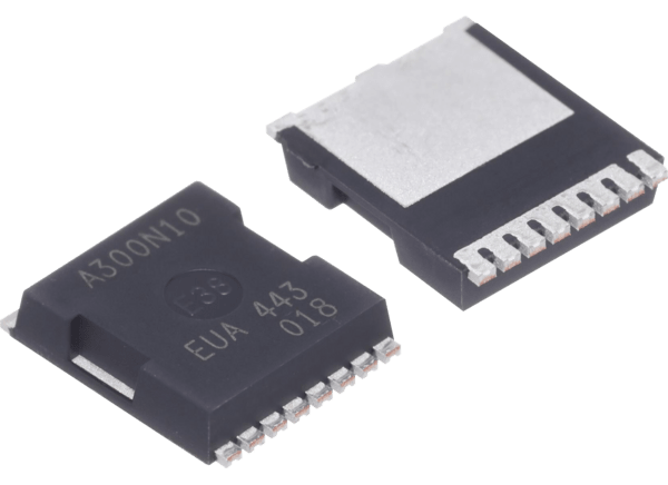
Figure 6: In addition to the MCU functions, a complete motion-control function requires low on-resistance MOSFETs with thermally efficient packaging, such as the REXFET-1 100V and 150V Power MOSFETs. (Source: Mouser Electronics)
Conclusion
Brushless DC motors are widely used for their reliability and potential for precise performance. FOC is an advanced algorithm that enables these motors to deliver accurate, efficient control of torque and speed through real-time current measurement and mathematical calculations. Compared to simpler control methods, FOC reduces torque ripple and enhances overall performance, but it also demands significant processing power for intensive computations, as well as specialized functionality and I/O. Until recently, these requirements limited the use of BLDC motors in lower-power applications such as power tools. However, advances in microcontrollers and integrated components are now making FOC practical for smaller, cost-sensitive designs. Renesas addresses these needs with a scalable family of cost-effective MCUs optimized for vector control, along with high-performance MOSFETs for driving motor coils.
Author Bio
 Bill Schweber is a contributing writer for Mouser Electronics and an electronics engineer who has written three textbooks on electronic communications systems, as well as hundreds of technical articles, opinion columns, and product features. In past roles, he worked as a technical website manager for multiple topic-specific sites for EE Times, as well as both the Executive Editor and Analog Editor at EDN. At Analog Devices, Inc. (a leading vendor of analog and mixed-signal ICs), Bill was in marketing communications (public relations); as a result, he has been on both sides of the technical PR function, presenting company products, stories, and messages to the media and also as the recipient of these. Prior to the MarCom role at Analog, Bill was associate editor of their respected technical journal, and also worked in their product marketing and applications engineering groups. Before those roles, Bill was at Instron Corp., doing hands-on analog- and power-circuit design and systems integration for materials-testing machine controls. He has an MSEE (Univ. of Mass) and BSEE (Columbia Univ.), is a Registered Professional Engineer, and holds an Advanced Class amateur radio license. Bill has also planned, written, and presented online courses on a variety of engineering topics, including MOSFET basics, ADC selection, and driving LEDs.