PMICs and Power-Rail Sequencing: Critical to Reliable System Performance
by Bill Schweber for Mouser Electronics
A high-performance IC such as an FPGA can easily have half a dozen or more distinct DC power rails to support the device core, RAM, internal buffers and external I/O such as I2C, SPI, LVDS and other ports. These rails may have different, but closely spaced, nominal values such as 1.2V, 1.5V and 1.7V, or several of these rails may have the same nominal value but different tolerances or physical locations. Similarly a highly integrated, application-specific IC such as a Wi-Fi network node may have multiple rails to support internal functions as well as interface voltages required by an industry standard. Or it may have a bipolar supply for the antenna driver and its power amplifier.
The power-rail count doesn't end with that single IC. The number of such rails will often increase further with the complete system, which may have motor drivers, power MOSFETs/IGBTs, or special communications interfaces such as Ethernet or even legacy RS-232/422 ports. As a result, regardless of physical size, the complete system may have ten or more rails sourced by independent DC regulators (also called power converters).
The Designer's Problem
The designer's problem is that when primary power is applied—whether via a discrete on-off switch or a soft-switch equivalent—these rails must often power up to their full final value in a carefully choreographed sequence (and there are also similar issues with the power-down sequence as well); see Figure 1. If the sequencing and relative timing is incorrect or has incorrect ramp up or ramp down rates, there may be permanent damage to the circuitry.
Figure 1: Power sequencing in multi-rail systems dictates that some rails be turned on only after others are fully on, or after others are at their final values. Turn-off requirements are also possible, as shown in this sequencing in an Altera Enpirion ES1021QI (Source: Altera Corp.)
Even if there is no permanent damage, operational malfunctions can cause an unacceptable consequence of incorrect sequencing: consider the effect of turning on the motor-power MOSFETs before the motor-control software is initialized and ready to control those MOSFETs. Nor do these problems have to be associated with a formal power-up event; instead they can be due to insertion of circuit cards in "hot swap" designs.
To deal with these issues, specialized power-management ICs (PMICs) are available that implement power sequencing and timing. A full-function PMIC allows the design engineer to:
- Establish turn on/turn off sequencing across multiple rails with respect to each other;
- Control the ramp up/ramp down rates of each rail, if needed;
- Manage the various rails if any single rail fails.
Generally the timing between rails is determined by rail voltages rather than absolute time delays, and the time period between the successive rails being "turned on" is on the order of milliseconds. The interrelationship guidelines range from simple, such as "turn supply B rail on only when supply A rail is on," to more complicated, such as "turn supply C rail on only when both A and B rails are at final voltage." (Note that "on" is defined by the application requirements and is most often 90% of final rail voltage, but in critical applications it may need to reach within 1% of final voltage.)
Even though in most designs it is the voltage that is critical, not the time itself, some designs substitute timing as the criteria instead. This is possible if the designer knows that a specific voltage rail takes a well-defined time to reach desired value, and timing is much easier to measure accurately than voltage. In these cases, a rule such as "turn on supply A rail once supply B is on" is translated into "turn B's rail on 50 msec after A's rail is turned on." However this approach has to be used with caution, as there is no verification that supply A's rail has actually come up to desired value, other than "it is supposed to be OK at this time."
Sequencing Power Rails Based on Positive Status/Feedback
Interestingly, there are some applications in which the timing period is much longer than the millisecond range. In these situations, several seconds (or longer) must pass before another rail is powered up. One example is where a function, such as a heater, must first come up to full temperature before the rest of the system is operational. Another example is where the system processor must run a calibration routine before turning on power to a high-voltage or high-power subsystem, but if the high voltage is turned on before a key transducer's readout is verified, electrical or physical damage may result.
Some PMICs integrate both the DC/DC regulators (LDO and switching) plus the requisite sequencing, and are optimized for a target application such as notebook PCs (CPU, memory, display, I/O and other standard functions). While these are obviously well suited to the intended application and should be considered in that context, they also inherently limit the overall flexibility in the designer's choice of voltage rails and types for other applications.
The requirement to sequence power supplies is not new. For example, for vacuum tubes—now made largely obsolete by ICs except for specialized applications such as X-ray machines or radio/TV broadcast transmitters—this is a common requirement: the filament may have to be turned on and at final operating temperature before the tube's plate can be energized by its "B+" voltage. This time delay ranges from zero for legendary consumer five-tube AM radio, to many minutes for tubes used in kW-range broadcast transmitters. The sequence is sometimes implemented manually by the system operator via on/off switches; in other cases, a special electromechanical relay with built-in timer is used. Certainly neither a manual or relay-based solution is practical for an FPGA-based product that fits in a pocket or briefcase.
Start the Physical Layer
In any discussion of power sequencing, it's easy to get so involved in the strategy for management of the many supplies and their rails that the basic issue of providing physical-layer control is pushed aside. It is important to keep in mind that there are two issues to address: the control signal coming from the sequencer, and the corresponding control input at each DC regulator (VREG).
For the first factor, the sequencer chosen must have enough control outputs, of course, or have some provision for expansion of the number if needed. These ports are simple, single GPIO (general purpose I/O) ports in most cases.
For the second factor, the DC regulators must either have a single-pin enable input, or the user must add an electronic switch (usually a MOSFET) between the regulator output and the physical power rail it drives, and then control this switch; see Figure 2. In most cases, it is preferable to choose a DC regulator that has a simple, logic-level enable control, if available, or a PMIC that can directly drive the rail MOSFET with suitable current/voltage ratings without a separate MOSFET driver.
Different solutions, wide span of flexibility
Sequencing is often considered a PMIC function, but this is a confusing area. Some PMICs focus on sequencing while others add other features, such as overcurrent or overvoltage protection. While these enhancements may seem worthwhile, the protection they offer can overlap or even be in direct conflict with similar features in the power-supply regulators themselves. Other PMICs provide little sequencing but instead focus on monitoring and reporting on the rails and their status. Therefore finding the right sequencing solution requires looking at PMICs as well as non-PMIC solutions.
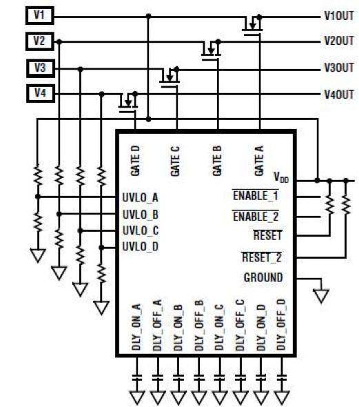
Figure 2: The PMIC output controls the VREG directly, or can drive an external MOSFET that acts as a switch between the VREG output and the rail itself; here, there are 4 such MOSFETs along the top between source Vx and rail VxOUT, where x is 1, 2, 3, or 4. (Source: Altera datasheet).
In the simplest case of sequential sequencing, where each rail is turned on in a series as another rail becomes "good," the solution is often simple. If each preceding rail's regulator has a "power good" (PG) output and the next regulator has an "enable" (EN) control input, the PG indicator is connected to the EN input. When the first regulator signals PG, it automatically turns on the next one, and so on down the line. See Figure 3.
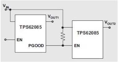
Figure 3: A simple but sufficient approach to sequencing in some situations is to have one regulator’s PG output become the EN input to the next regulator; here, 2 sequenced TI TPS62085 step-down regulators supply DC rails VOUT1 and VOUT2 (source: Texas Instruments datasheet).
This approach will work for any number of DC regulators in a series, but that virtue is also its limit: they must have a sequential pattern (although one PG can be connected to more than one EN), and there is little flexibility. Also this approach cannot control timing when one supply must wait a specified interval before turning on, and it cannot address turn-off sequencing, which may be as important as turn-on sequencing.
To overcome some of these issues, a reset IC with timer control can be used for power-up sequencing. The venerable and versatile 555 timer IC (or newer variant) can be used to control sequencing by invoking a time period after the first rail reaches the nominal window value, or after a rail shuts down. The time period is set in hardware by using resistors with the 555, so it is established by design and BOM, not firmware; see Figure 4. While this may not appear to be an elegant approach, it is an effective one, especially useful when a sequencing problem becomes visible only after the design is done and prototype boards are being evaluated.
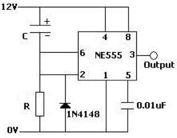
Figure 4: Another simple solution in some designs is to use a simple 555-type IC as a basic timer to provide a delay established by resistor value.
For systems with more rails that require more flexibility, a PMIC such as the MAX16029 from Maxim Integrated can be used for four channels, with the time-delay period user-programmed via capacitors, thus avoiding memory volatility or start-up issues; see Figure 5. Each of the four channels is independent of the others, and each channel output can be used in an open-drain configuration, which supports rail voltages up to 28V, needed for higher-range DC regulators. Other PMICs with this functionality have their timing set via a PMBus interface rather than capacitors or resistors, and so can be daisy-chained to handle more than four rails.
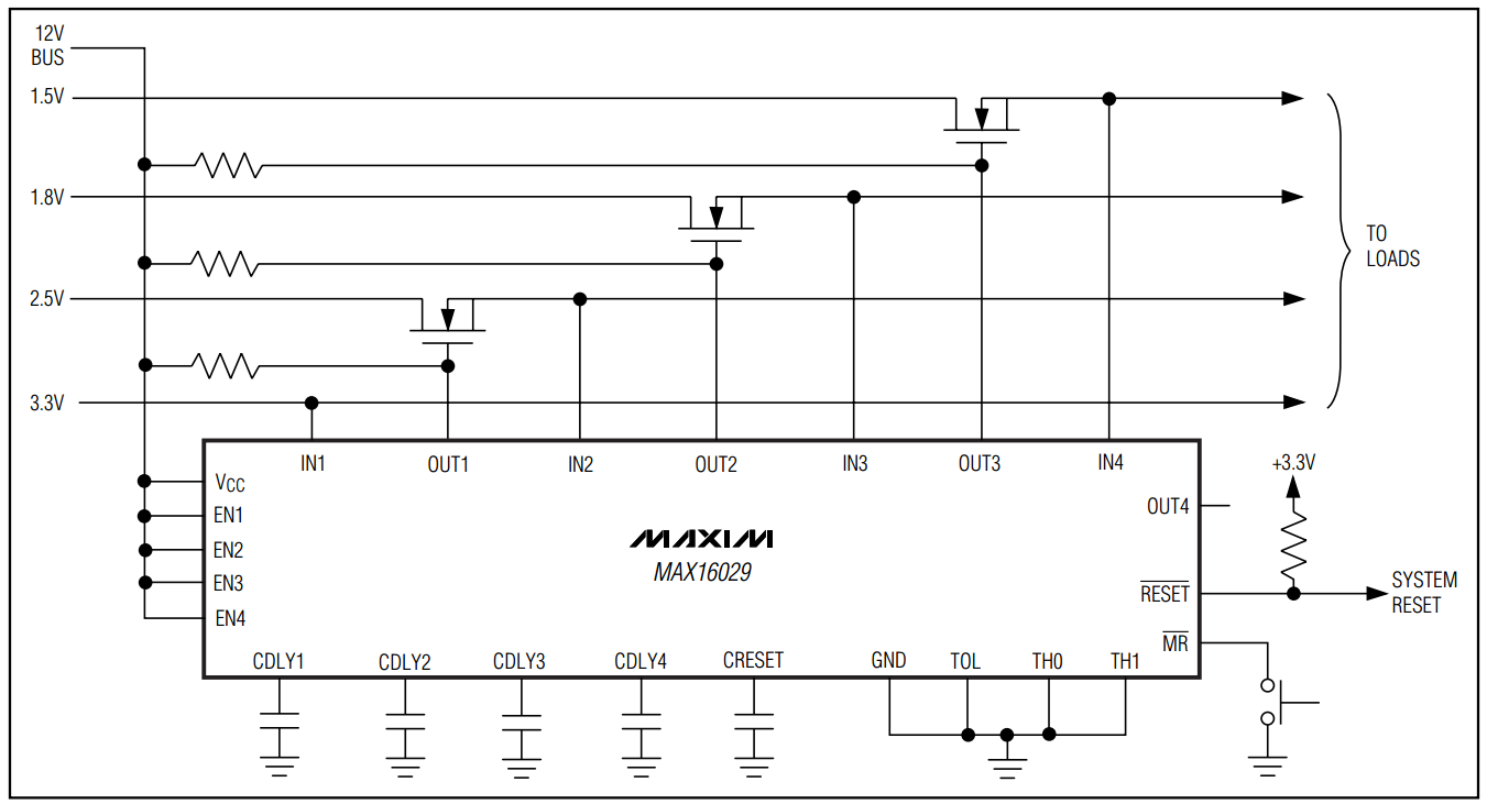
Figure 5: The MAX16029 PMIC from Maxim Integrated uses capacitors to program the time delays of four independent channels, and supports DC rails up to 28V (source: Maxim Integrated datasheet).
Firmware, software offer higher-end solutions
For applications with many rails, complicated sequencing requirements and a need to more fully manage turn-on and turn-off sequencing, the previous approaches may be insufficient or require many additional components. There are two paths to resolving this sequencing challenge, both offering the needed capabilities. One is based on a user-programmed microcontroller; the other uses a fully programmable IC that is designed for sequencing.
For example, a power sequencer using a member of the Microchip Technology PIC16F1XXX family can handle four, eight or more power sources; see Figure 6. The embedded firmware is user-programmed for desired sequencing attributes, along with power-good criteria, ramp-up time and ramp-down time, as well as implementing various alarm modes if a supply goes out of range or fails. The PIC-based approach has a 10-bit ADC but digitizes each rail 16 times and then averages the result, yielding the equivalent of a 4-bit conversion. the PIC16F1XXX family selected, the number of GPIO pins for enabling a voltage regulator or driving a rail MOSFET can be in the dozens, and thus capable of handling almost any situation.
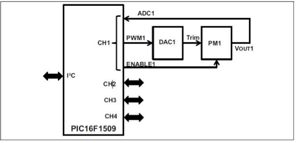
Figure 6: Using a power sequencer based on the Microchip Technology PIC16F1XXX family provides flexibility in sequencing and timing across many rails, as well as detailed performance criteria as measured by its internal ADC (source: Microchip Technology datasheet).
For a sequencing-specific device, UCD90120A from Texas Instruments offers another fully programmable approach; see Figure 7. This 12-rail power-supply sequencer and monitor is addressed by a PMBus/I2C interface, and also includes 26 GPIO pins that are available for other supply-related functions, such as generating supply enables, resets and alarm interrupts to the system processor. When combined with a suitable graphical user interface (GUI), it can be used for establishing complicated power-on/power-off sequences and timing, and providing insight for system-failure analysis if a brownout occurs; see Figure 8.
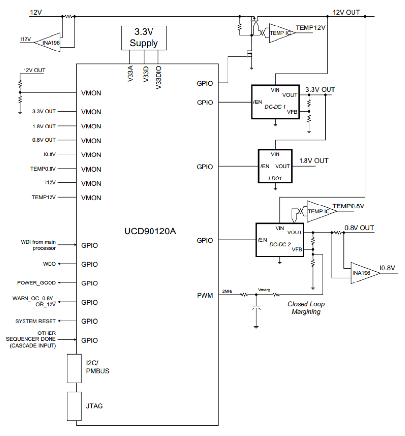
Figure 7: The UCD90120A from Texas Instruments is designed for sequencing and monitoring of up to 12 rails, and is user-programmable via its PMBus/I2C interfaces; additional GPIO pins enable additional supply-related sensing and control options (Source: TI datasheet.)
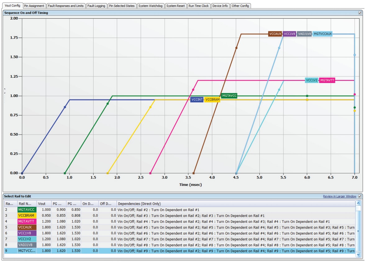
Figure 8: Combining a flexible PMIC such as the UCD90120A with a GUI yields a powerful tool for establishing multiple, complex sequencing scenarios, and observing the performance of each rail as well as their timing relationships (source: TI Application Note).
Summary
Power supplies and their rails may not have the glamour or get the attention that processors receive. However they are an increasingly important function of a successful, reliable design in high-capability, high-performance designs ranging from handheld smartphones and instrumentation to server farms and data centers. Managing the disparate rails is not an easy task, but many options for power-supply sequencing and PMICs are available that match features to project requirements. These solutions range from simple cascaded sequential enables to sophisticated, fully programmable ICs with advanced functions, offering the ability to establish and change the values of many key parameters.