Stepper Motors Make the Right Moves with Precision, Ease and Smarter Drivers
by Bill Schweber, Mouser Electronics
The stepper motor is both a creation and an enabler of the modern era of electronic products. As a technology creation, it required the development of:
- small, powerful permanent magnets for the rotor
- semiconductor power devices to switch its electromagnetic coils on and off
- smart electronics to drive the switches with the correct sequence and timing
- all at low cost, of course. As a technology enabler, it is a key element providing the small, low-cost, precise motion needed for products such as printers, scanners, cash-dispensing ATMs, small disk and tape drives, camera pan/zoom tilt (PZT) controls, and innumerable other small-to-medium appliances with which we are surrounded (Figure 1).
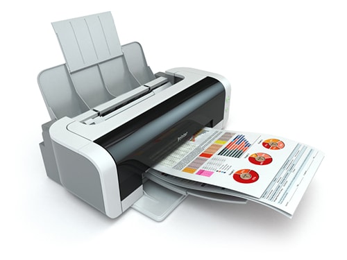
Figure 1: Stepper motors are ubiquitous due to their low cost and high performance. They serve unnoticed in countless applications such as consumer printers to move the print head and feed the paper. (Source: IStockPhoto.com)
Stepper Motor Basics
The basic structure of the stepper motor begins with a look at its predecessor and still-popular cousin, the brushless-DC (BLDC) motor (Figure 2). In the most-common BLDC motor design, permanent magnets are placed on the rotor, and electromagnets are located around the periphery of the stator. When the electromagnetic coils are energized, the rotor will line up accordingly due to the attraction between the rotor's permanent magnets and the stator's coils. By reversing the current flowing to the coils, or switching some of the electromagnets off and on in rotational sequence (both techniques are used, for different applications), the rotor will spin as it follows the changing magnetic field that these coils generate. By changing the switching frequency, the speed of the motor's revolutions will change as well. As with the BLDC motor, the frequency of the energizing sequence determines the rotational speed.
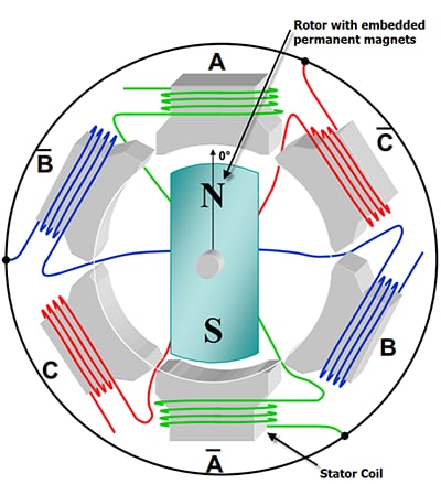
Figure 2A: Illustration showing BLDC motor wiring.
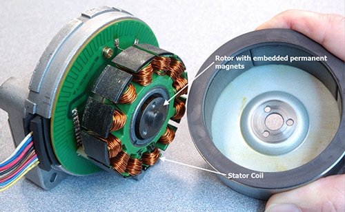
Figure 2B: A spoke design BLDC motor. Understanding the operation of the stepper motor begins with the still popular brushless-DC motor, the stepper motor's predecessor, which uses the interaction between rotor-mounted permanent magnets and fixed, stator-mounted electromagnetic coils. (Source, Figs 2A & 2B: Dave Wilson, Texas Instruments)
The principle of stationary, switched coils interacting with permanent magnets on a rotor is the basis for the permanent-magnet stepper motor. There are many variations on this basic design, including the hybrid motor, which combines the stepper motor with a variable-reluctance motor. To build a stepper motor , the number of permanent magnets on the rotor - called poles - is increased compared to the basic BLDC motor, typically with as few as twelve (30° spacing) and as many as 200 (1.8° spacing) (Figure 3). There's a trade-off as the number of poles increases, since the rotational resolution increases (usually a good thing), but the cost increases and available torque decreases (not good).
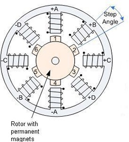
Figure 3: The stepper motor uses a ring of electromagnetic poles that interact with an array of permanent magnets mounted on the rotor. As these poles are energized and de-energized, the rotor follows their magnetic field. (Source: Anaheim Automation)
Although it is just an extension of the BLDC motor in some ways, the stepper motor is a much more complicated component than the BLDC motor. Due to the array of rotor magnets, the motor can be advanced in finite steps, or increments, and will stay at a given position as long as the coils remain energized and are not being sequenced. As a result, the stepper can be rotated to a precise angle, can establish a specific position and can easily be controlled to develop larger and smaller amounts of rotation. While a stepper can be used for continuous rotation, the performance in that role is not as good as a BLDC design. Instead, the stepper's strength is the ability to rotate through or to a specific angle, stop, start, and reverse as needed, and to do so quickly.
Many steppers are used in conjunction with a basic gear train or mechanism to provide rotation-to-linear motion, such as what is needed to move the print head or paper in a printer. In principle, because the stepper motor's angle is determined by energizing the coils, the position of the rotor will always be known, and therefore the system can operate "open loop" without a feedback sensor. The reality is that overloading, problems with the drive train or load, and other issues can cause the rotor to go out of step with the drive, and so many stepper applications use a sensor and closed-loop mode to report the actual rotor position. Others use a "reset" mode where they move the stepper's load, such as a print head, back to a known home location and then reset the stepper zero position.
Two electrical configurations are in wide use for wiring of the coils (poles) used in stepper motors; each has an associated drive topology. In the most commonly used approach, called a two-phase design, two types of winding arrangements are used: unipolar (also called unifilar) and bipolar (bifilar), (Figure 4). These two methods offer trade-offs in drive requirements, motor size, weight and other factors.
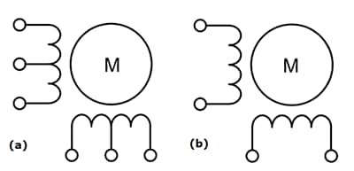
Figure 4: The poles of the stepped motor can be wound as (a) a center-tapped unipolar winding, which allows the field to be reversed by turning one winding off and the other on; or (b) as a bipolar winding, which requires reversal of the current flow to reverse the field. (Source: ON Semiconductor).
In the unipolar stepper motor, there is a single center-tapped winding per phase, with one section of winding switched on to change direction of magnetic field. The magnetic pole can be reversed without switching the direction of current, so the commutation circuit for each winding can be as simple as a single low-cost transistor (Figure 5). A typical two-phase motor has three leads per phase, totaling six leads; the commons of these two phases are often connected, so the motor has only five leads.
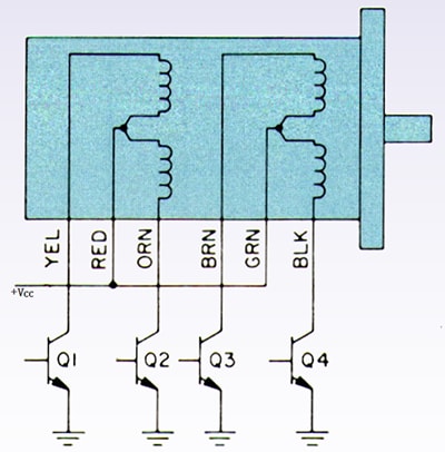
Figure 5: The unipolar winding arrangement is simple to drive, with a transistor switch for each winding. The transistors do not need to "float," but can use a single-ended supply and share a common ground. (Commutation diodes not shown. Source: Airpax Stepper Motor Handbook, 1989)
In contrast, bipolar motors use a single winding per phase, so the current in a winding must be reversed to switch a magnetic pole. As a result, the driving circuit is more complicated, and usually implemented via an H-bridge. There are two leads per phase and none are common, for a total of six to eight leads for a multiphase motor, with the actual number depending on various configuration aspects.
Since only half of the windings are used at any time in the unipolar arrangement, its copper cost and ratios of power to weight and to size are less favorable than they are for the bipolar windings. On the other hand, the electrical-drive arrangement is more complicated for the bipolar setup. However, modern-stepper driver ICs easily take care of the drive topology, making this aspect of winding and stepper-motor selection almost a non-issue.
Stepper-Motor Attributes
Stepper motors have some unique characteristics compared to other motor designs. Their relative advantages include:
- They can provide precise positioning and repeatability of movement, and a well-designed stepper motor will have positional accuracy between 3 and 5 percent of a step; also important, this error is non-cumulative from one step to the next.
- They can provide full torque at low and even zero rpm, and are well-suited to rapid start/stop/reverse situations.
- They are mechanically reliable since there are no commutators or brushes to wear out; the bearing is the only part subject to wear.
- They can be used as open-loop motors in many applications, saving the cost of the feedback sensor.
- Applications that do not need high resolution can use lower-cost versions with fewer poles.
- They are easily controlled by digital signals from a processor or dedicated controller.
However, they are not necessarily the optimum choice for every application. Some of their disadvantages include:
- They are not well-suited to high rpm or continuous motion, nor are they appropriate as higher-power motors (above the equivalent of 1/100 to 1/20 horsepower, or roughly 10 to 50 W).
- They are not as efficient in use of power as BLDC motors.
- They can lose synchronization or skip steps due to electrical or mechanical issues, and may need a feedback sensor, as well as electrical detection of stall and stop conditions.
- In use, they tend to chatter and vibrate, as a sort of cogging action. (There are ways to manage this, discussed below.)
- Stepper motors can exhibit mechanical resonances at certain step rates, which is a function of their speed (rpm), the drive train and the load dynamics. Resonance results in a drop or loss of torque.
Microstepping: an Enhanced-Step Technique
There are two benefits to microstepping. First, the motor's operation becomes smoother, and many problems related to cogging and resonance can be avoided. Second, it becomes possible to position the rotor between the poles, thus increasing the effective positional resolution (although with a decrease in available torque, typically between 10 and 30 percent). Microstepping is a well-understood technique and many stepper controllers can implement its complicated details, under the direction of the supervisory function. As such, it is a no- or low-cost option for improving stepper-motor performance.
The previous discussion assumed that the electromagnetic poles were switched on or off rapidly, at high slew rates. An improved approach uses half-stepping, where poles are turned partially on and off, thus doubling the apparent number of steps. A more-advanced approach is called microstepping, which uses a ramping or a sinusoidal-shaped on/off waveform for power switching (Figure 6). As a result, some poles are energizing while others are de-energizing, with a crossover or overlap between the two.
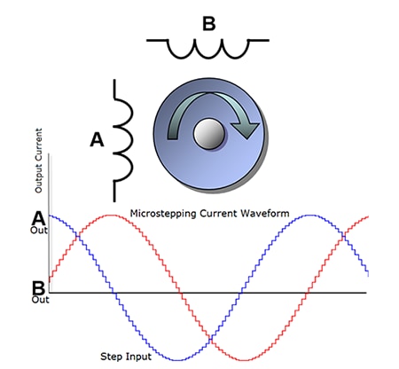
Figure 6: In microstepping, the current drive is composed of a series of small steps with a sine-like shape. The result is both smoother rotor motion and the ability to index between the poles, for greater effective angular resolution than the number of poles alone allows. (Source: Texas Instruments)
Key Stepper-Motor and Driver Parameters
Designers usually look at their motor requirements first, by matching the load with a potential motor, and then by working back to find a driver that has the features, functions and power to fit both the application needs and the chosen motor. The electronic parameters can be looked at separately from the mechanical ones, but the two are closely related.
Mechanical factors include step angle, motor size, weight and mounting style. The industry has established many standardized sizes and mounting configurations, so units from different vendors can be used in the same installation as second or alternate sources (Figure 8). Other mechanical considerations include issues such as tolerance and axial/radial play in the rotor. A vital mechanical specification is the rotor's inertia (usually specified in oz-in2 or gram-cm2 for smaller motors) since it is a major factor in defining how fast the motor can be accelerated or decelerated at maximum drive.
Figure 7: The HT17-268D stepper motor from Applied Motion Products is a representative unit with an industry-standard NEMA 17 frame and mounting holes. Key specifications include 1.8° step angle, 1.34 A/pole current, 31.2 oz-in minimum holding torque and 5.38 oz-in2 rotor inertia. (Source: Mouser Electronics)
Vendors also provide parameters such as maximum torque at full-rated drive current, torque versus speed curves and holding torque at zero rpm. The mechanical design of the electromagnetic coils establishes the DC resistance and inductance of the coils, which are the loads that the motor presents to its electrical drivers. These, in turn, are related to the motor-drive current and voltage requirements.
Drivers Show Stepper Motor Ease of Use
IC vendors have made driving a stepper motor relatively straightforward. A stepper-motor driver IC supplies the needed timing, waveform shaping, current drive, embedded algorithms, coil-drive FETs, and protection circuitry (thermal, overcurrent, and open circuit) for direct connection to smaller motors. It may also have the FET-driver circuitry needed for switching external FETs which larger motors require and where an integrated, single-chip solution is not feasible. (Note: the term "driver" is ambiguous and must be understood from the context. It can refer to a MOSFET that directly controls the motor; it can be a MOSFET-driver functional block- and is sometimes called a pre-driver- that switches the MOSFET which, in turn, controls the motor; or it can be an entire motor driver with power circuits, waveform control and I/O.)
A representative example of a stepper driver that uses external MOSFETs is the DRV8711 bipolar stepper driver from Texas Instruments (Figure 8). The IC interfaces to a host microcontroller via an SPI port to provide the DRV8711 with high-level definition and selection of motor profile, stepping mode, and 256-microstep operation, MOSFET drive current, and other factors. It operates from a single supply between 8- and 52-V, and drives the external MOSFETs set up in an H-bridge configuration. It includes important protection features such as stall detection and notification via back EMF, thermal protection and overcurrent shutdown.
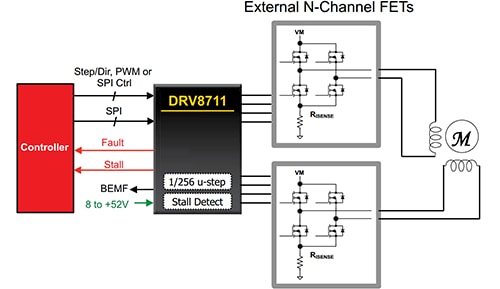
Figure 8: The DRV8711 bipolar stepper-motor driver from Texas Instruments takes overall direction via the SPI bus, implements various stepper-drive and performance profiles, and then drives external MOSFETs that switch the motor poles. (Source: Texas Instruments)
Nearly all motor-control vendors offer comprehensive packages that include reference designs and evaluation boards. The LV8714TAGEVK from ON Semiconductor (Figure 10) allows prospective users of their LV8714TA stepper driver to exercise the device and fold it into their design, if desired, via supplied Gerber files, BOM information and code modules. The LV8714TA is a dual-stepper driver that operates from 4-to 16.5-V and includes four H-bridge channels with power FETs, to directly drive two independent stepper motors for applications such as scanners, point-of-sale printers and video PZT brackets. It is designed to automatically go into an extremely low-power mode when not in use, and then quickly wake up and execute motion directives. The kit includes PC-based development software, a USB interface cable, circuit board with all associated components and two small motors.
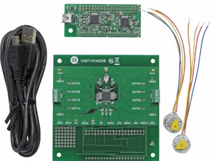
Figure 9: Most motor-control vendors offer full design support, such as this LV8714TAGEVK development kit from ON Semiconductor for their LV8714TA motor-driver IC, which comes complete with cables, reference design, software and two small motors. (Source: ON Semiconductor)
Some designers prefer not to use a stepper driver to integrate algorithms and control, but instead program their algorithms in the system microprocessor or microcontroller, and then have that processor's digital outputs connect to basic-function MOSFET drivers. This is a viable strategy if the processor has available computation power and time, or it is optimized for control applications.
For OEM designers considering this option, it's crucial to understand who is providing the control algorithms that will reside in the processor- the IC vendor, a third party or the OEM- and how these will be tested. Also, the embedded software must be designed to deal with the many soft and hard faults, and idiosyncrasies that all motors encounter. Some vendors even offer special versions of their processors with additional integrity and reliability functions to ensure the motor-related code will continue to run under all conditions.
As with the driver-only products, vendors offering the processor-centric approach also provide complete development kits with the necessary software that can be tailored to the application specifics. Many vendors offer both the processor-based and embedded-driver solutions, so the user can assess both approaches and judge the relative merits of each with respect to the application requirements and priorities.
 Bill Schweber is an electronics engineer who has written three textbooks on electronic communications systems, as well as hundreds of technical articles, opinion columns, and product features. In past roles, he worked as a technical web-site manager for multiple topic-specific sites for EE Times, as well as both the Executive Editor and Analog Editor at EDN.
At Analog Devices, Inc. (a leading vendor of analog and mixed-signal ICs), Bill was in marketing communications (public relations); as a result, he has been on both sides of the technical PR function, presenting company products, stories, and messages to the media and also as the recipient of these.
Prior to the MarCom role at Analog, Bill was associate editor of their respected technical journal, and also worked in their product marketing and applications engineering groups. Before those roles, Bill was at Instron Corp., doing hands-on analog- and power-circuit design and systems integration for materials-testing machine controls.
He has an MSEE (Univ. of Mass) and BSEE (Columbia Univ.), is a Registered Professional Engineer, and holds an Advanced Class amateur radio license. Bill has also planned, written, and presented on-line courses on a variety of engineering topics, including MOSFET basics, ADC selection, and driving LEDs.