Design Guidelines for Optocoupler Safety Agency Compliance
Introduction to Electrical Safety
Traditionally, electrical isolation from hazardous voltages has been the most common application for optocoupler devices. Other applications for optocouplers include reducing EMI through the elimination of common-mode current loops, which are the greatest contributors to radiated emissions in high-speed digital systems. However, isolation is still the predominant role for optocouplers in today's electronics marketplace. Electrical isolation is important in modern electronics design as a way of minimizing the likelihood of exposing an enduser to injury from hazardous currents. The currents at which harm or even death can occur are far lower than most people think. In certain invasive medical operations, currents as low as 80 μA can be fatal and have an acceptable safety limit of 10 μA. These thresholds are outlined in figure 1.
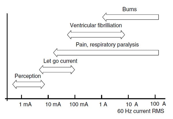
Figure 1: Shock Hazardous Levels
Electrical isolation is typically achieved by one of three methods: magnetic, capacitive, or electrooptical. All three have their pros and cons. Magnetic isolation (using an isolation transformer) is probably the longest-established method of electrical isolation, providing high levels of isolation at high frequencies in a robust package. Among the downsides of this method of isolation are a large device footprint when compared with other methods and suitability only for AC signal coupling. Due to these characteristics, magnetic coupling is for the most part limited to high-power AC applications.
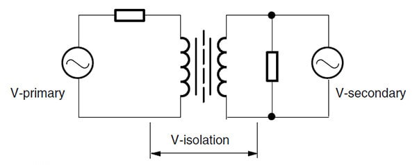
Figure 2: Magnetic Isolation
The second common method of electrical isolation is capacitive coupling. The advantages of capacitive coupling are high switching speeds and a relatively small package footprint, but to eliminate the need for a floating power supply on the secondary side, a large capacitance is required to transfer energy from the primary to the secondary side. Thus, the electrical isolation value of this technique is greatly diminished by the need for efficient energy coupling. Consequently, most capacitive coupling isolation schemes have isolation values in the hundreds of volts rather than the thousands of volts achievable with other methods.
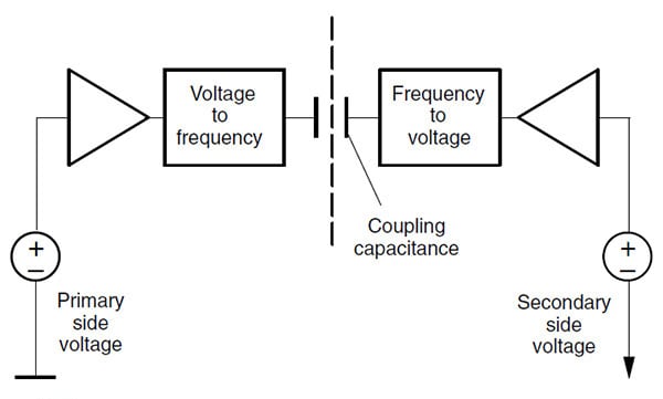
Figure 3: Capacitive Isolation
Another potential isolation method involves the use of magneto-resistive sensors. These sensors are able to detect DC as well as AC magnetic fields. However, this is an emerging technology and is susceptible to induced noise from extraneous external magnetic fields.
Optical isolation has many of the best aspects of the former methods without the drawbacks. Mainly, optical isolation offers high electrical isolation values, an effective "line in the sand" barrier that hazardous voltages are incapable of penetrating. In the case of Vishay's couplers, these values are as high as 8000 V, the highest level in the industry. This is achieved with small-footprint packages and high speed; moreover, it is equally effective with AC or DC signals.
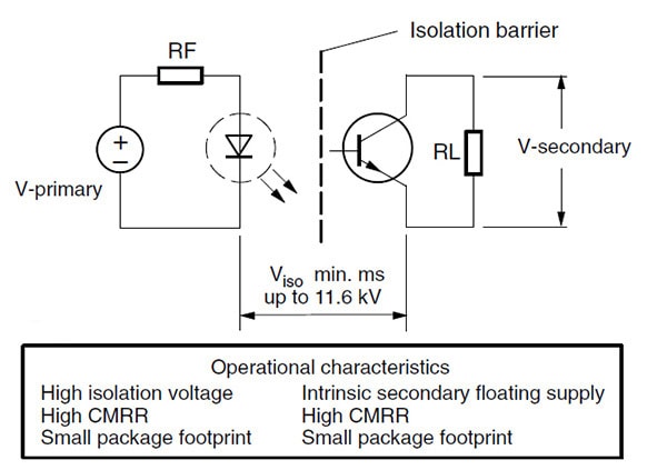
Figure 4: Electro-Optical Isolation
Safety Agency Standards Overview
There are several widely accepted industry standards that govern the manufacture and testing of electronic equipment. Probably the most widely known of these in North America is Underwriter's Laboratories (UL). UL has two types of basic approvals: UL Listing and UL-recognition. The difference is simple but often a subject of much confusion. The "UL Recognized" mark, optionally inscribed on the devices themselves, refers to components that have been evaluated to a certain extent by UL and will be "re-reviewed" by UL for proper incorporation into the end-use equipment. A "UL Listed" mark is placed on complete equipment. For example, a computer would be a UL Listed, while the component hard drive would be a UL Recognized part. As seen in the next page, UL was concerned enough about potential confusion between the meanings of these two marks that it intentionally made them distinct from one another.

Figure 5: UL Listed/UL Recognized
UL has safety standards for everything that is or possibly can be manufactured; however, to simplify things, these standards can be divided into two groups: system standards and component standards. The system standards are beyond the scope of this document to address in their entirety. Arguably, the most commonly applicable system standard in the electronics industry is UL60950, which governs the electrical safety requirements for the broad category of information technology equipment (ITE). In addition to information technology, there are also standards that deal with other specialty fields of product electrical safety. Of particular interest to optocoupler design is IEC 60601-1, which governs the safety of medical equipment. IEC 60601-1 was generated by those in the medical field worldwide, and it is the basis for many countries' national standards, such as UL2601-1 in the United States. Similarly, UL 60950 has been based on the internationally generated IEC 60950 and adopted with changes due to unique national conditions in the United States, including the National Electrical Code (NEC).
The European Union adopted the IEC-based version as EN 60950. As is the case for all components, optocouplers do not necessarily need to meet all particular end-use system standards, such as IEC 609050 or IEC 60601-1. In trying to meet any of the specific system standards, it is important to know which component parameters create design limitations. For safety purposes, these parameters include creepage (along a surface) distances, clearance (through air) distances, maximum isolation voltages, and insulation thicknesses. For the most part, this document will deal with standards exclusively dealing with the manufacture and testing of optocouplers. These are covered under two standards, UL1577 and IEC 60747-5-1, which incorporate and supersede the earlier DIN EN 60747-5-5. In addition to these standards, which explicitly deal with optocouplers, the latest version of IEC 60950-1 clauses, 2.10.5.1, 2.10.7, 2.10.8 , ANEX P.1, and ANEX P.2, also address issues that deal with optocouplers directly.
UL 1577
The main UL component standard, addressing optocouplers in the United States is UL 1577, which covers the safety specifications that pertain to optocouplers in North America. This document offers an outline of the specification and points out the highlights that deal with electrical safety.
Generally, all tests classified as "type tests" refer to those tests performed to validate a particular design to a standard. They are conducted by qualified testing laboratories, often only once before serial production begins. This is in contrast to routine tests, also known as 100 % production line tests, which are intended to prevent manufacturing defects from ever leaving the factory. In other words, 100 % production line tests are designed to assure that products coming off the line are confirmed to be constructed as those evaluated during the type tests. The first sections of UL1577 deal with package construction issues, materials, corrosion protection, spacing, thermal testing, etc.
The section of greatest interest is section 16.2, which specifies "rated dielectric insulation voltage" testing. It specifies a test at the rated dielectric insulation voltage for 60s; however, it gives the manufacturer the option of testing at 120 % of the rated dielectric insulation voltage for only 1 second. For obvious efficiency concerns, the 1 s test is much more desirable. Thus, on a Vishay optocoupler data sheet, a "minimum isolation test voltage", or "isolation voltage for 1s", is actually 120 % of the rated dielectric insulation voltage. Consequently, the actual rated dielectric insulation voltages are arrived at from Table 1, where they are identified by "system type" (family of related components).
|
Table 1 - Production Testing Conditions
|
||||
| OPTO. Family (System Type) |
60 s Test VAC RMS |
60 s Test VDC |
1 s VAC RMS |
1 s VDC |
| A, C, D | 1500 | 2120 | 1800 | 2550 |
| B, H, J | 4420 | 6250 | 5304 | 7500 |
| E | 3748 | 5300 | 4498 | 6360 |
| F | 1980 | 2800 | 2376 | 3360 |
| G | 3536 | 5000 | 4243 | 6000 |
| S, Y, O | 2500 | 3536 | 3000 | 4200 |
| I, V | 1473 | 2083 | 1769 | 2500 |
| T | 3750 | 5303 | 4500 | 6364 |
| L | 1250 | 1768 | 1500 | 2122 |
| U | 3125 | 4419 | 3750 | 5303 |
In addition to the general optocoupler standards listed above, there is one additional component classification, that of "double-protection" optical isolators, which is a fairly unique evaluation specific under UL 1577. This is often confused with the more commonly used IEC-based terms of "double insulation" and "reinforced isolation". Both terms, explained in great detail in IEC60950, are briefly defined as follows:
Reinforced insulation: A single, robust level of insulation that meets a high level of constructional and performance requirements at a single point. This can be thought of as a high-integrity component, such as a power transformer with low-voltage outputs or an optocoupler with at least a 0.4 mm minimum insulation thickness to fulfill this requirement. Most of Vishay's optocouplers fulfill this criterion. Those that do will indicate the required 0.4 mm minimum insulation thickness. Vishay's unique over-under double-molded construction inherently provides excellent dielectric insulation characteristics.
Double insulation: An insulation system, equivalent in principle to the above in that it prevents the operator from being exposed to hazardous currents, that consists of the sum of basic insulation and a secondary, independent fault-protection method. Such an insulation system should protect the end-user from any single point of failure of the primary insulation medium. One of the most common methods of providing secondary fault protection is to use a grounded metal chassis, which is designed to trip a fault-protection device should the line fault to the chassis. Another would be to employ a completely independent insulation system such as would be provided by a plastic chassis.
Double protection: does not refer to either of the above common IEC defined terms but rather is a performance test, outlined in the UL1577 standard. All of Vishay's system H and J parts have been tested and conform to the double protection standard. The double protection test basically involves subjecting the part under test to 20 kV pulse discharges and then testing the device using a partial discharge method to verify that no permanent damage has been incurred. The apparatus used to perform the double protection test is described below.
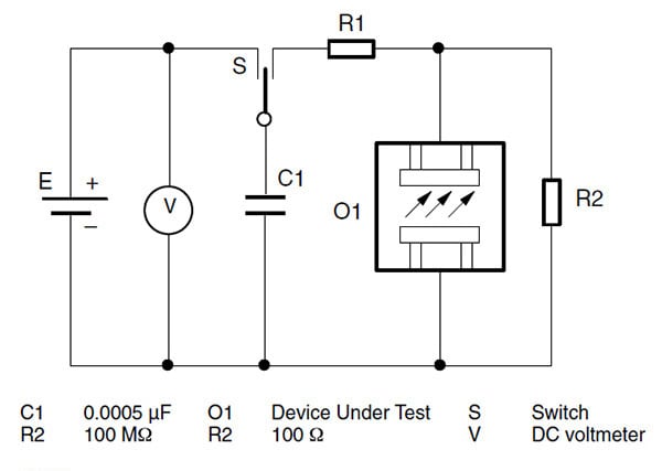
Figure 6: Circuit Discharge Test
DIN EN 60747-5-5/IEC 60747
The main German standard-writing body, VDE (Verband Deutscher Electrotechniker), has a different approach to optocoupler safety testing and certification than the UL. This approach relies to a much lesser degree on assumptions regarding the viability of insulation thickness.
Rather than assuming that a particular insulation thickness guarantees the electrical dielectric barrier required to maintain a given standard of electrical safety, the VDE method of testing and certification admits the possibility that the insulation could be flawed by voids due to cracks, air bubbles, etc., and compromised over time by voltage transients. This approach allows for a higher degree of confidence in the insulation system, as well as a more flexible approach to meeting a given isolation standard. Using this approach, it is possible to meet an isolation standard with an insulation of lower thickness than would be required by perspective standards that are based strictly on insulation thickness. The consequence of this higher standard of safety confidence is the need for more frequent and accurate testing.
The key to the VDE method of testing is the partial discharge test. As in the case of UL1577, VDE testing methodology includes testing 100 % of the manufactured devices in question to an elevated voltage for 1 s and testing for dielectric breakdown. However, the VDE standard for dielectric failure is extremely tight. It allows for leakage from the "ganged" input-to-output pins of no greater than 5 pC. Furthermore, this elevated voltage test is done at a lower voltage than the required UL high-pot test, reducing the possibility of component damage during the test. Moreover, in addition to the 100 % partial discharge test on the production line and a type or qualification test during the engineering evaluation phase, VDE requires a destructive sample testing by random sampling tests throughout the manufacturing process. The destructive type and batch sample test is described in figure 7.
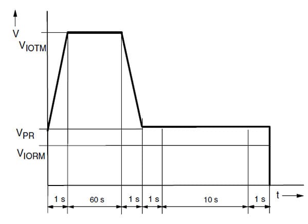
Figure 7: VDE TYPE and Sampling Destructive Test
VIOTM and VIORM are parameters designated by Vishay based on the inherent material and construction characteristics of particular parts. These are provided in the Vishay data book for each specific part in question. VIOTM refers to the impulse voltage value of a particular device, and it will be important for determining "usage category", which is described in detail later on in this document. VIORM is the maximum recurring peak voltage, or maximum operation voltage, which is one of the parameters used when determining the maximum continuous operating voltage. VPR, the partial discharge test voltage, is derived from VIORM, being 1.875 VIORM for 100 % production line testing and 1.5 VIORM to 1.2 VIORM for various stages of type testing.
In addition to the destructive tests that are performed for type qualification and sample batch testing, VDE requires a partial discharge test to be performed for every single part as a routine test. Moreover, preceding the partial discharge test, Vishay performs an isolation voltage test for 1 s for each and every part coming through production. This test is performed on all Vishay optocoupler parts, whether or not they are required to meet the DIN EN 60747-5-5 standard, because it is a test also required for UL 1577. It is described in
figure 8.
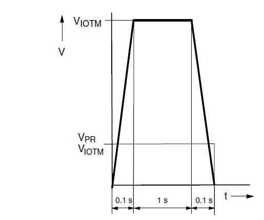
Figure 8: Isolation Voltage Test
For those parts that comply to DIN EN 60747-5-5 or IEC 60747, a partial discharge test is conducted subsequent to the isolation test described above. This partial discharge test consists of applying an elevated voltage from the input side to the output side of the optocoupler device under test and measuring the leakage current from primary to secondary. The leakage current allowed is 5 pC. Consequently, this is an excellent test for measuring the insulation integrity of a device, much more so than the use of a prescribed minimum insulation thickness. This test is described in figure 9.
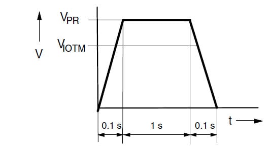
Figure 9: Partial Discharge Test Profile
In addition to the UL and VDE/IEC specs described above, Vishay couplers are also certified by several other regional "competent bodies" such as CSA, which is accredited by the Standards Council of Canada, and notified bodies in the European Union such as BSI and FIMKO. Whether or not a specific part is certified by a specific agency can be determined by looking at the Vishay Agency Approval Table, and if there are any doubts, this may be ascertained by contacting Vishay directly. All of these additional approvals involve the submission of product to various regulatory agencies and notified bodies, and do not require any additional production line testing.
Installation Category
An additional issue to consider when addressing the electrical safety issues involved with the use of optocouplers is "installation category". Installation category refers to a grouping of equipment based on where the end-user product is located in the power distribution system, and therefore what overvoltage transients the circuits would be expected to tolerate. For example, the worst-case installation category IV would be a power meter that is connected directly to the main power feed and does not benefit from the additional transient protection that is enjoyed by systems farther downstream from the main power feed. This would require the highest-possible transient withstand voltage, and it would be the highest installation category. The further away equipment is from the main power feed, the lower will be the required transient withstand voltage and installation category. This concept is illustrated below.
In addition to how close to the utility line equipment resides, a second consideration to take into account when determining installation category is utility line voltage. UL60950 for ITE only details spacings with the assumption that the products covered under the standard are category II, so the decision of the installation category is essentially made for the manufacturers when they choose to abide by standards such as UL60950.
|
Table 2 - IEC-664 Installation Categories
|
||||
| Utility Voltage Phase To Earth VRMS OR DC |
Impulse Withstand Voltages in Volts for Installation Category VIOTM (From Vishay VDE Tables) | |||
| Installation Category I | Installation Category II | Installation Category III | Installation Category IV | |
| 50 | 330 | 500 | 800 | 1500 |
| 100 | 500 | 800 | 1500 | 2500 |
| 150 | 800 | 1500 | 2500 | 4000 |
| 300 | 1500 | 2500 | 4000 | 6000 |
| 600 | 2500 | 4000 | 6000 | 8000 |
| 1000 | 4000 | 6000 | 8000 | 12000 |
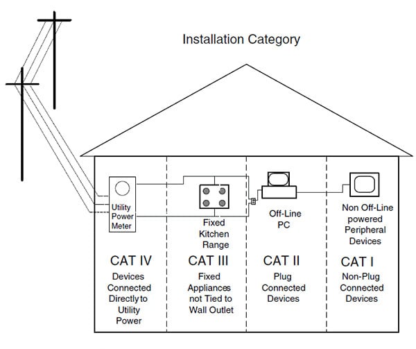
Figure 10: Installation Category
Creepage and Clearance
Crucial points of interest when trying to meet any specific system standards are creepage and clearance parameters. Creepage is defined as the shortest distance between two conductors over a material's surface. Clearance is simply the shortest distance between two conductors through air. These two parameters, discussed in great detail in EN 60950, and other IEC standards do not apply where insulation is relied upon to isolate circuits, but do apply where there are potential paths "around" the insulation. Both of these parameters are provided in the Vishay product data sheet as they apply to Vishay optocouplers. They are explained in figures 11 and 12.
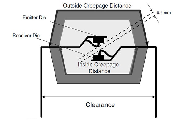
Figure 11: Over-Under, Double-Molded Optocoupler Crossection
In addition to the standard clearance paths, option 6 and option 8 can increase the spacing paths by in-creasing the lead spread as illustrated in figure 12.
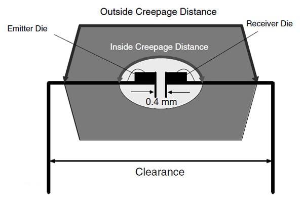
Figure 12: Coplanar Optocoupler Crossection
Designers should note that often it is the pad-to-pad spacing on the circuit boards themselves that is the limiting factor for the allowable spacing requirements. Most printed wiring board manufacturers do not evaluate their boards for comparative tracking index (CTI) ratings, so the worst-case material group IIIb (as defined in IEC 60950) is almost always assumed, with hard-to-control soldermask not depended upon as a reliable insulating means.
Some manufacturers place 1 mm wide minimum slots in the board for pollution degree 2 environments to break up the creepage distance requirement and meet only the clearance distance. See figure 13.
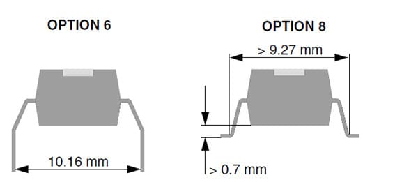
Figure 13: Lead Spacings
Design Example
A power supply designer wants to sell an existing AC-to-DC switching power supply, which is agency-approved for the ITE industry under UL60950, to the international (IEC based) industrial control market that normally sits upstream of ITE in the building's branch circuit distribution. That is, the power supply would be used in an installation category-III environment instead of II. The product will be used in a 208 V application. Table 2 shows that a 4000 V impulse withstand voltage (or VIOTM) is required. Also, in the supply there is a maximum repetitive peak working voltage of 350 Vpk in the front end of the supply that may appear at the optocoupler, so it should be selected with the minimum repetitive peak working voltage (or VIORM) of 350 Vpk. VIOTM and VIORM values are often confused with the isolation test voltage (or dielectric or high-pot rating). The spacings (creepage and clearances) would then need to be checked, with the circuit board's pads usually being the limiting factor. Vishay's spacings are typically shown on the specification sheets.
Conclusion
It is important to reemphasize the difference between system-level standards and component-level standards. The procedures and standards discussed in this document refer to component-level standards and must be looked at in that context. If issues arise regarding specific system standards such as IEC 60950, IEC 60601, etc., Vishay applications engineering is able to deal with questions as they may pertain to the optocoupler requirements. Meeting system electrical safety standards is an issue that must be addressed on a final system level, and it cannot be completely addressed by simply choosing the right optocoupler.
Useful Web Links
References
- Webster, G. John, "Medical Instrumentation Application and Design". New York: Wiley, 1998.
- Burek, Robert & Linehan, James, "Product Safety for ITE, Telecom, Laboratory, and Test and Measurement Equipment". Compliance Engineering, Foxborough, 1998.
- UL 1577 Standard for Safety for Optical Isolators.
- IEC 60950 Safety Standard for Information Technology Equipment.
- IEC 60747-5-2 Standard for Optoelectronic Devices.