SafeGear Check: AI-Powered PPE Detection with Nicla Vision for Workplace Safety Compliance

Image Source: Ahmad Soleh/Stock.adobe.com; generated with AI
By Venesha Arockiasamy, Mouser Electronics
Published December 4, 2025
According to a study by the US Department of Labor Occupational Safety and Health Administration (OSHA), 70 percent of workers who sustained serious hand injuries were not wearing gloves at the time.[1] This is just one example of how personal protective equipment (PPE) could prevent injuries in the workplace if workers had worn it.
This project introduces SafeGear Check, a safety-gear-detecting system that scans individuals as they enter a work area to ensure they are wearing the required PPE. The system employs the Arduino Nicla Vision artificial intelligence (AI) camera module and an AI model trained on Edge Impulse. The system includes lights and a speaker for visual and voice feedback based on the detection results.
In this project, you will learn how to build the SafeGear Check system, including connecting the Nicla Vision outputs to a web interface to improve system efficiency.
Project Materials and Resources
Project Hardware
- Arduino Nicla Vision
- Adafruit tower lights
- 12V external power supply
- DFRobot DFPlayer mini MP3 player
- Same Sky CMS-235-18L152 speaker
- Raspberry Pi A2 class microSD card
- Soldered resistor kit
- EPCOS 1000 µF radial capacitor
- Central Semiconductor bipolar NPN transistors (3)
- Diotec Semiconductor rectifier diodes, DO-41, 1000V, 1A (3)
- BusBoard Prototype Systems BB830T breadboard
- Grayhill tactile switches (4)
- Micro USB Cable
Project Code/Software
- Edge Impulse
- OpenMV integrated development environment (IDE)
- Visual Studio Code
- GitHub project repository
Additional Resources
Project Hardware Overview
The Arduino Nicla Vision (Figure 1) is an AI-integrated camera module designed for image analysis and processing. The module features a proximity sensor based on the STMicroelectronics VL53LIX time-of-flight (ToF) sensor to measure distance. The Nicla Vision is suitable for object recognition and asset tracking. The module’s six-axis inertial measurement unit (IMU) allows it to capture 3D accelerometer data, enabling machine learning for object recognition.

Figure 1: Arduino Nicla Vision module. (Source: Mouser Electronics)
Project Software Overview
The project uses the following software applications:
- Edge Impulse trains the AI model to identify the PPE by inputting several images of each piece of PPE from existing data sets.
- OpenMV IDE uploads and tests the Edge Impulse model in Nicla Vision. It also contains the code for all the operations that the Nicla Vision must perform, such as controlling the lights and speaker based on the detection results.
- Visual Studio Code (VS Code) is the web interface (frontend and backend) where employers set the required PPE, and employees log in to be scanned.
Developing the Project
The goal of this project is to train the AI model to identify specific types of PPE, upload the model to the Nicla Vision module, and program the module to control the lights, proximity sensor, and speaker for visual and voice feedback. The project also includes the development of a web interface that enables employers to specify the required PPE and employees to sign in and show they are wearing the PPE.
We will begin by training the AI model in Edge Impulse and then proceed to the hardware and software components.
Training the Edge Impulse Model
Edge Impulse is an AI platform for training models and deploying them to edge computing devices, such as the Nicla Vision. By uploading datasets of images of several pieces of PPE, we can train the AI model to identify them on the workers.
To start training the model, you will first need images of workers wearing each piece of PPE (e.g., helmets, vests, masks), which can be found in existing datasets, such as those available from Roboflow Universe. To ensure the model can correctly identify the PPE, collect at least 100 images for each piece of PPE, including images from different angles and images of people wearing it. This will enable the model to identify workers wearing PPE—which is the primary goal—rather than just the PPE itself.
- Open Edge Impulse and click Create New Project.
- Click Data Acquisition in the left navigation pane.
- Click Upload to upload all the images that you collected.
- Click Labeling Queue to display the images that you just uploaded.
- For each image, click the sample name (Figure 2), draw a bounding box around the PPE, and label it.
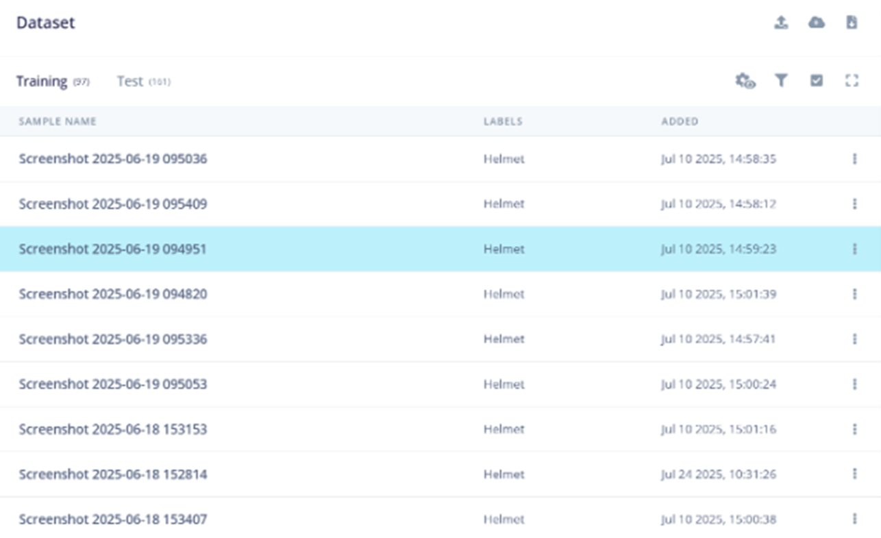
Figure 2: Labeling queue. (Source: Mouser Electronics)
Note: When labeling the PPE, ensure that you draw the bounding boxes so they include the person wearing the PPE (Figure 3). For example, if you want to label a helmet, draw a bounding box around the worker’s head with the helmet. This will ensure the model identifies that a worker is wearing a helmet, rather than identifying just the helmet itself.
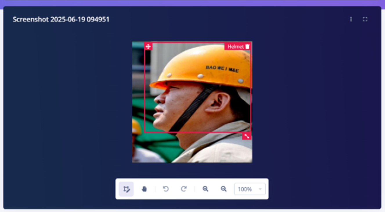
Figure 3: Drawing and labeling bounding boxes. (Source: Mouser Electronics)
- Click Create Impulse to configure the impulse settings (Figure 4).
- In the Image Data block, enter 72 for both the width and height. In the Resize Mode dropdown menu, select Fix shortest axis.
- In the Image block, type Image in the Name field and select Image from the dropdown menu.
- In the Object Detection (Images) block, type Object detection (Bounding Boxes) in the Name The block’s name will change to Object detection (Bounding Boxes).
- Select the Image Under Output features, enter the number and names of your PPE labels.
- Click Save Impulse.
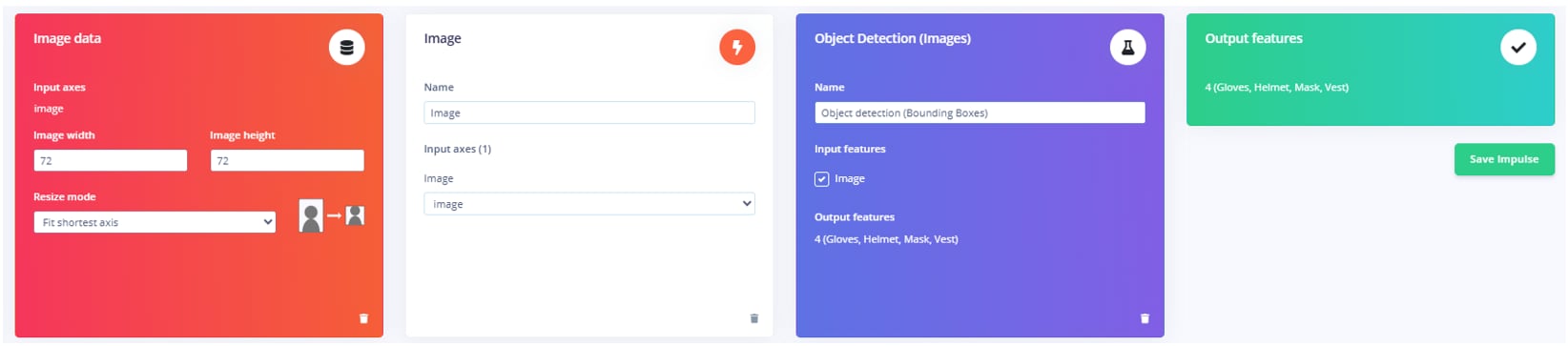
Figure 4: Impulse settings. (Source: Mouser Electronics)
- Click Object Detection (Bounding Boxes).
- In the Neural Network settings window that opens, enter the following parameters (Figure 5).
- Number of training cycles: 100
- Use learned optimizer: deselect the checkbox
- Learning rate: 0.001
- Training processor: CPU
- Data augmentation: select the checkbox
- Validation set size: 20%
- Profile int8 model: select the checkbox
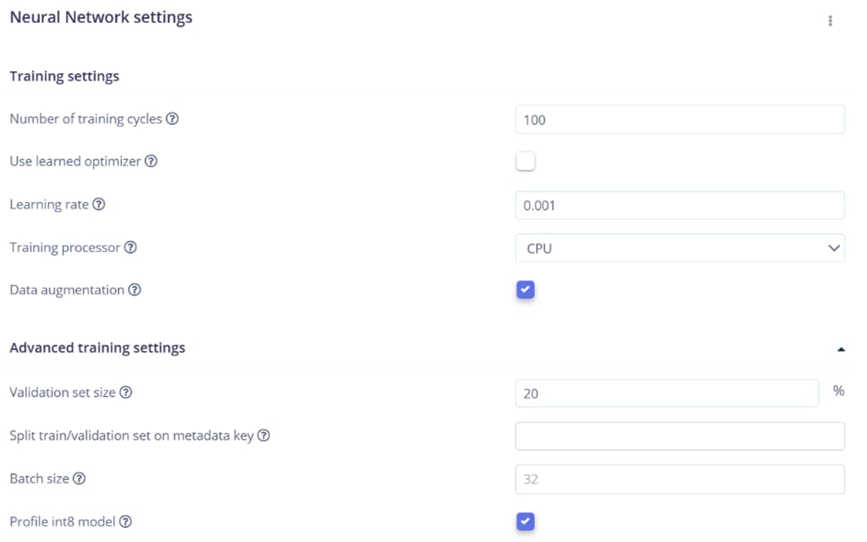
Figure 5: Neural network settings. (Source: Mouser Electronics)
- Under Neural network architecture (Figure 6), select FOMO (Faster Objects, More Objects) MobileNetV2 0.35.
- Click Save & train.
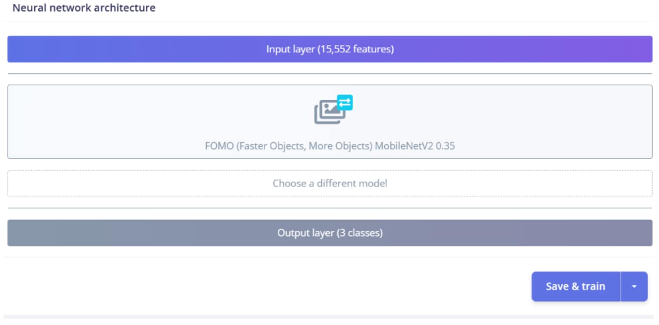
Figure 6: Neural network architecture settings. (Source: Mouser Electronics)
The tool displays the model’s training performance based on the images you uploaded (Figure 7).

Figure 7: Model testing performance. (Source: Mouser Electronics)
Note: If the percentages are low for certain PPE, upload more images and retrain the model. Click Live Classification to test your model with other images and determine whether it can accurately identify the PPE.
- Once you have perfected and tested your model, click Deployment in the left navigation.
- Search for and select OpenMV Library as the deployment option, and then click Build (Figure 8).
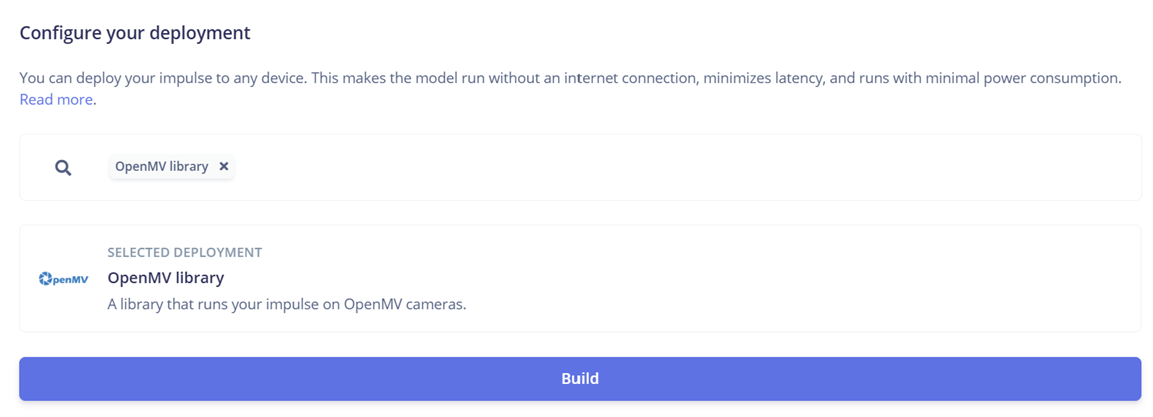
Figure 8: Deploying the OpenMV library. (Source: Mouser Electronics)
The tool creates a ZIP folder containing the trained model, labels, and a Python file that contains the code for the object recognition model. Extract all of these files.
Running the Model on OpenMV IDE
Now that you have trained your model using Edge Impulse, upload it to the Nicla Vision and test it again on the OpenMV IDE.
- Connect the Nicla Vision to your computer using the Micro USB cable.
- Upload the extracted trained.tflite and labels.txt files into the Nicla Vision’s storage folder, which automatically opens.
- Open the OpenMV IDE.
- Click the white connect icon at the bottom-left corner of the window to connect the Nicla Vision to OpenMV IDE.
- Click the green play button in the bottom-left corner of the window to run object_detection.py (Figure 9).
- The camera should become active on the right side of the window. Test your model by showing the camera pictures of different PPE.
- Click the Serial Terminal tab in the bottom left corner of the window. This will display the camera’s outputs. For example, if you show the camera a worker wearing a helmet, the serial terminal displays Helmet (Figure 9).
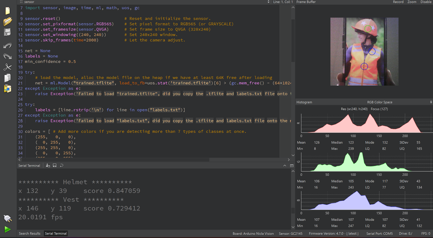
Figure 9: Nicla Vision running the trained Edge Impulse model on OpenMV IDE. (Source: Mouser Electronics)
Connecting the Hardware
The schematics in Figure 10 illustrate the required hardware connections for the system to work properly. Follow the connections to the pin numbers exactly, as the code also includes these specific connections.
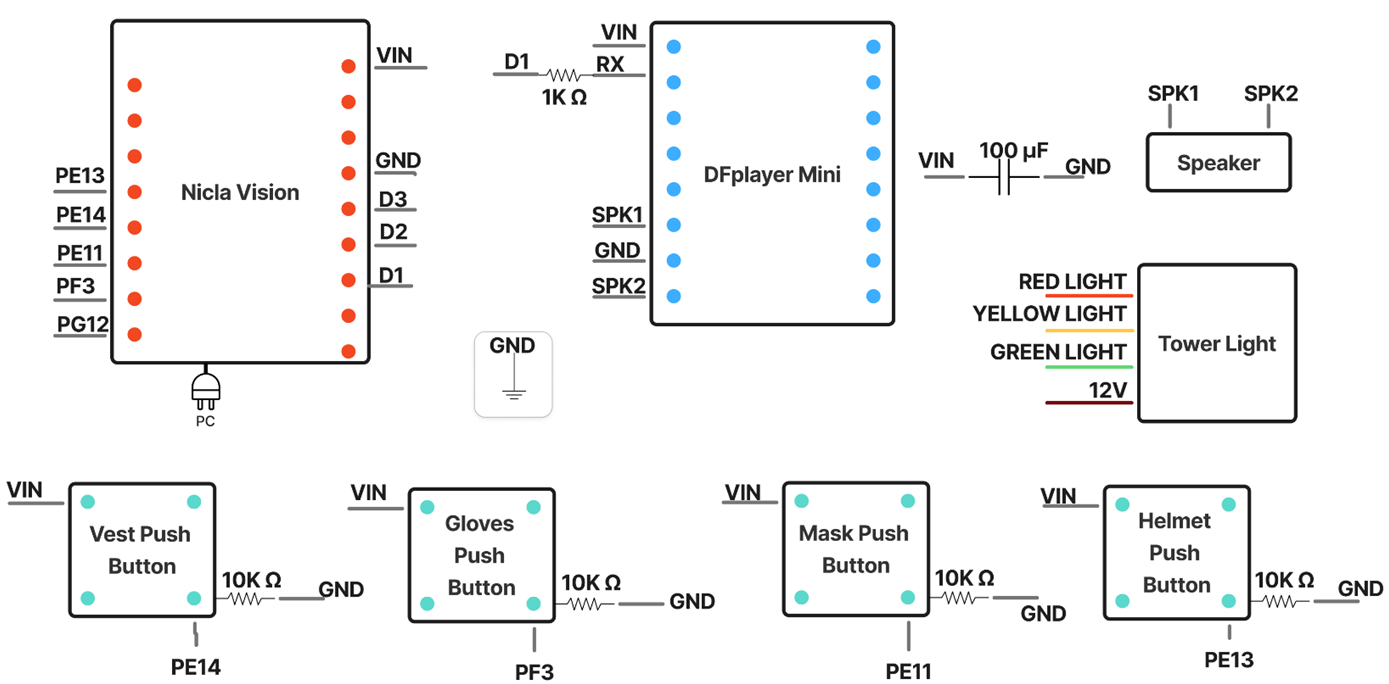
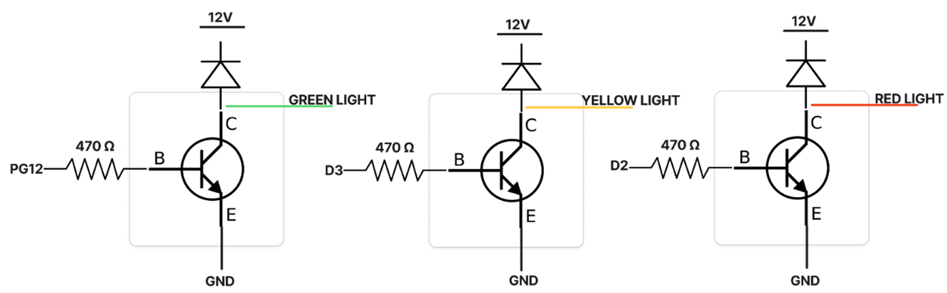
Figure 10: SafeGear Check hardware schematic. (Source: Mouser Electronics)
Figure 11 shows the completed circuit on the breadboard.
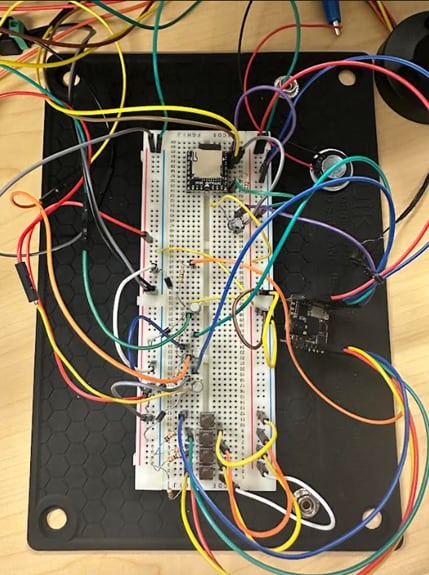
Figure 11: Fully built SafeGear Check circuit. (Source: Mouser Electronics)
Follow these steps to create the circuit:
- Connect the push buttons.
- For each push button, find two terminals on opposite corners (i.e., diagonal terminals). Connect one diagonal terminal to VCC.
- Connect the other diagonal terminal to one end of a 10KΩ resistor and connect the other end of the resistor to GND.
- From the same terminal as the resistor, connect a wire to the Nicla Vision pin assigned to that button: Helmet button PE13, Vest button PE14, Mask button PE11, Gloves button PF3.
- Repeat steps 1–3 for each push button.
- Connect the tower light.
- Connect the emitter of each of the three NPN bipolar transistors (one per color channel) to GND.
- Connect the base of each transistor to one end of a 470Ω resistor.
- Connect the other end of each resistor to the corresponding Nicla Vision output pin—PG12, D2, and D3, respectively.
- Connect each collector to the corresponding tower light color wire:
- Green light wire: Collector of PG12 transistor
- Red light wire: Collector of D2 transistor
- Yellow light wire: Collector of D3 transistor
- Connect each collector through a diode to the +12V line to protect the transistors and LEDs from reverse voltage conditions. (NOTE: +12V is only for the tower lights; the grounds must be common, but the voltage rails must be isolated.)
Debug tip: If you cannot control the tower lights with the transistors, use a multimeter in diode mode to verify each transistor is functioning correctly. Check the base-emitter and base-collector junctions for proper forward voltage drop (typically 0.6V–0.7V).
- Connect the DFPlayer.
- Connect one end of a 1KΩ resistor to the DFPlayer’s RX terminal, and connect the other end to the Nicla Vision pin (D1).
- Connect the positive terminal of the 1000 µF capacitor to the DFPlayer’s VCC and the negative terminal to the DFPlayer’s GND.
- Connect all ground wires to the ground rail on the breadboard.
- Plug the power supply into the wall and plug the Nicla Vision into your computer.
Adding to the OpenMV Code
Now that you have a working model that can correctly identify all the required PPE, you can import libraries, initialize hardware, and add logic statements to the code in OpenMV.
Importing Libraries
Use the following code to import the necessary libraries:
import sensor, image, time, ml, math, uos, gc, pyb
from machine import Pin, I2C
from vl53l1x import VL53L1X
from pyb import UART
- The sensor and image libraries enable the Nicla Vision camera to scan the person standing in front of it and determine whether they are wearing the required PPE.
- The time library defines the duration of detection for the Nicla Vision itself.
- The ml library contains the machine learning model.
- The math library enables all calculations used in the model.
- The uos library handles the file system operations, including files on the microSD card.
- The garbage collection (gc) library frees unused memory.
- The pyb library controls all the hardware inputs from the Nicla Vision, as well as the communication between the PC and the Nicla Vision.
- The Pin and I²C libraries allow the Nicla Vision to control hardware such as the tower light and speaker.
- The VL53L1X library enables the use of the proximity sensor.
- The UART library enables communication with the DFPlayer and speaker for voice feedback.
Initializing the Hardware
To connect the three status lights and four push buttons to the Nicla Vision, you must initialize them. Refer to the schematic in Figure 10 and ensure that the physical connections match those specified in the code.
green_led = Pin("PG12",Pin.OUT)
yellow_led = Pin("D3",Pin.OUT)
red_led = Pin("D2",Pin.OUT)
button_helmet = Pin("PE13",Pin.IN)
button_vest = Pin("PE14",Pin.IN)
button_mask = Pin("PE11",Pin.IN)
button_gloves = Pin("PF3",Pin.IN)
Initializing the Log File
To save worker information and detection results, you must first create a text file named system_log.txt. Then, include that filename in the code (e.g., LOG_FILE = “system_log.txt”). This tells the system to create a timestamped record that includes the date, worker name, and detection results.
def log_event(username, message):
try:
dt = rtc.datetime()
timestamp = "{:04d}-{:02d}-{:02d} {:02d}:{:02d}:{:02d}".format(dt[0], dt[1], dt[2], dt[4], dt[5], dt[6])
log_entry = f"{timestamp},{username},{message}\n"
with open(LOG_FILE, "a") as f:
f.write(log_entry)
except Exception as e:
print(f"ERROR: Failed to write to log file: {e}")
Initializing DFPlayer and the Speaker
The following code demonstrates how the UART is configured to communicate with the DFPlayer Mini for voice output based on detection results. Each command sent to the DFPlayer follows a fixed frame structure: It begins with a start byte (0x7E); includes a version byte, command length, and other parameters; and ends with an end byte (0xEF). The DFPlayer uses this frame to set volume and select the appropriate audio file for playback.
START_BYTE = 0x7E
VERSION_BYTE = 0xFF
COMMAND_LENGTH = 0x06
END_BYTE = 0xEF
ACKNOWLEDGE = 0x00
uart = UART(9, 9600)
uart.init(9600, bits=8, parity=None, stop=1, timeout_char=1000)
Connecting the USB COM Port
Because the DFPlayer and speaker use the UART connection, you must establish a USB connection so that the Nicla Vision’s detection results can be seen on the web interface. This is an important step because it establishes communication between the Nicla Vision and the web interface over USB.
usb = pyb.USB_VCP()
Setting the Proximity Sensor Threshold
The following code sets the maximum distance that the VL53L1X ToF sensor can detect (1,000mm) and instructs the system to activate when the sensor detects movement or presence.
PROXIMITY_THRESHOLD_MM = 1000
tof = None
try:
tof_i2c = I2C(2)
tof = VL53L1X(tof_i2c)
print("INFO: Proximity sensor initialized.")
except Exception as e:
print(f"ERROR: Proximity sensor not found. Error: {e}")
Once the proximity sensor is activated, the yellow tower light turns on (Figure 12), and the Nicla Vision starts detecting the worker’s presence. The system shows the presence detection once the worker has signed in.
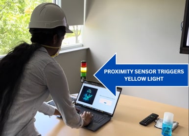
Figure 12: Proximity sensor triggering the yellow tower light. (Source: Mouser Electronics)
Initializing the Push Button Inputs
The following code initializes the push buttons and allows you to select the required PPE. Each selected item will appear on the web interface under Employer Settings.
When you finish selecting PPE and click Log Out, the system updates the list and sends it to Nicla Vision, which then uses this list to verify that workers are compliant with the required gear.
while(True):
is_helmet_pressed = (button_helmet.value() == 1)
is_vest_pressed = (button_vest.value() == 1)
is_mask_pressed = (button_mask.value() == 1)
is_gloves_pressed = (button_gloves.value() == 1)
required_items = []
if is_helmet_pressed:
required_items.append("Helmet")
if is_vest_pressed:
required_items.append("Vest")
if is_mask_pressed:
required_items.append("Mask")
if is_gloves_pressed:
required_items.append("Gloves")
current_gear_list = ",".join(required_items)
if current_gear_list != last_gear_list_sent:
print(f"GEAR_LIST:{current_gear_list}")
last_gear_list_sent = current_gear_list
Creating Logic Statements for Detection Results
After initializing all the hardware connections, create the logic statements for the detection results. These statements define how the system responds to the presence of or lack of PPE. If the Nicla Vision detects all required PPE, the green light illuminates, the web interface displays an “all clear” message, and the speaker plays the “all clear” audio file. If the Nicla Vision fails to detect all of the PPE, the red light illuminates, the web interface displays which items are missing, and the speaker plays the “missing gear” audio file.
if all_gear_found:
final_result_message = "All clear. Please proceed to the site."
green_led.high()
send_command(0x03, 0x00, 0x02)
print(f"RESULT:{final_result_message}")
time.sleep_ms(500)
else:
final_result_message = "MISSING GEAR: {}. Please wear all required safety gear before entering the site.".format(", ".join(missing_items))
red_led.high()
send_command(0x03, 0x00, 0x01)
print(f"RESULT:{final_result_message}")
Developing the Web Interface Using Visual Studio Code
This project uses VS Code to manage both the front-end and back-end of the web interface. The front-end files define the page design, making it accessible to both employers and employees. These files are located in the public folder, which contains the employee dashboard page, employer and employee login pages, and the employer settings page (Figure 13).
To access these files, open the SGC-WEB project in VS Code. Once opened, the left panel (i.e., Explorer) will display all folders within SGC-WEB, including the public folder.
The server_app folder contains the server.js file, which includes the serial port connection from the Nicla Vision to the web interface.
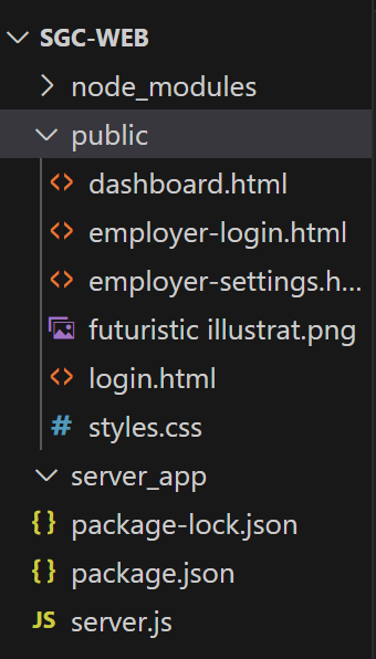
Figure 13: Visual Studio Code files layout. (Source: Mouser Electronics)
The following code establishes the web interface and the serial port connection to create and set up the server.
const express = require('express');
const http = require('http');
const { Server } = require("socket.io");
const { SerialPort } = require('serialport');
const { ReadlineParser } = require('@serialport/parser-readline');
const app = express();
const server = http.createServer(app);
const io = new Server(server);
The following code manages the data exchange between the push-button interface, the Nicla Vision, and the web application. The parser.on('data', ...) function listens for serial messages sent from the Nicla Vision to the Node.js backend. When input data representing the selected safety gear is received, the server emits a gear-list-update event to the web interface. After processing, the Nicla Vision sends detection results, indicating whether the selected safety gear was identified, which are then emitted as a detection event. These results control the corresponding visual indicators on the web interface and sound on the speaker.
parser.on('data', (data) => {
console.log('Data from Nicla:', data);
if (data.startsWith('GEAR_LIST:')) {
const listString = data.substring(10).trim();
io.emit('gear-list-update', listString);
}
});
parser.on('data', (data) => {
console.log('Data from Nicla Vision:', data);
if (data.startsWith('RESULT:')) {
const userMessage = data.substring(7);
io.emit('detection', userMessage);
} else if (data.startsWith('ERROR:')) {
io.emit('detection', data);
}
});
The remaining portion of the server.js file defines the server routes using Express. These routes specify which front-end files (such as the login page or employer dashboard) are served to the browser and what actions occur when users interact with the web interface (for example, submitting a username, logging in, or navigating between pages). The file also includes logic for initializing the server when you run node server.js, which starts the web interface. Console log statements are included throughout the code to verify that all functions, from user login and gear detection to logout, are executing correctly and that the system is running as intended. Before running the server, check the COM port assigned to the Nicla Vision in your computer’s Device Manager, and ensure it matches the port specified in server.js (for example, COM5). This ensures proper serial communication between the Nicla Vision and your PC.
Execution
Now you are ready to integrate all hardware and software components (Figure 14).
- In VS Code, open a terminal in the folder containing server.js and run npm init to create the package.json file. This will initialize the node.js environment.
- Run npm install express to install the Express framework (which generates the node_modules folder and updates package-lock.json).
- Run npm install to install any additional packages listed in package.json.
These dependencies enable the backend to communicate with both the web interface and the Nicla Vision.
- Save the OpenMV IDE code in OpenMV IDE for the Nicla Vision and all front-end and back-end files in VS Code.
- Unplug and reconnect the Nicla Vision to prevent port conflicts.
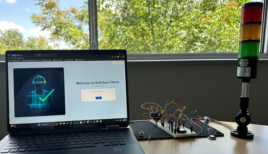
Figure 14: Final setup of SafeGear Check. (Source: Mouser Electronics)
In the following steps, you will run the server.js file to open the web interface, then sign in as the employer to configure the settings, and, finally, sign in as an employee to test the system functionality while wearing the PPE.
- Run node server.js on a VS Code terminal (Figure 15).
This provides a clickable link: http://localhost:3000.
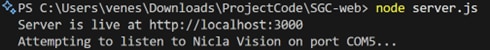
Figure 15: Running the server.js on VS Code terminal. (Source: Mouser Electronics)
- Click the link to open the web interface for SafeGear Check (Figure 16).
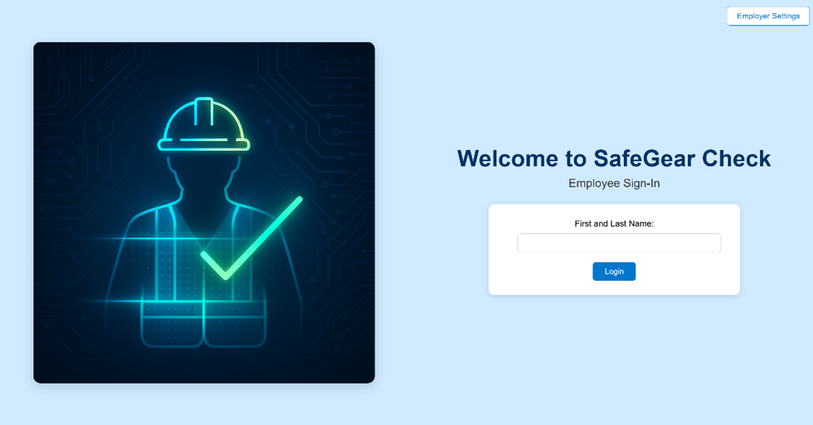
Figure 16: The Employee Sign-In page is also the main landing page. (Source: Mouser Electronics)
- Click the Employer Settings button in the upper-right corner of the page.
- On the Employer Sign-In page (Figure 17), enter “Mouser” as the Employer ID. If necessary, you can modify this field in the “employer-login” file in VS Code.
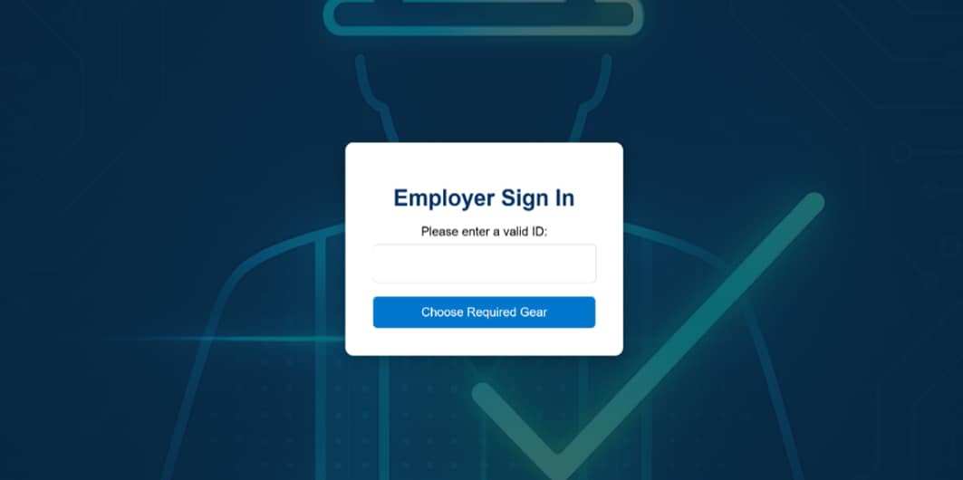
Figure 17: Employer Sign-In page. (Source: Mouser Electronics)
- The Employer Settings page (Figure 18) shows which buttons on the circuit correspond to which PPE. On the breadboard, press the buttons corresponding to the required PPE.
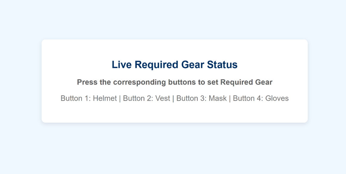
Figure 18: Employer Settings page. (Source: Mouser Electronics)
- As you press the buttons, the corresponding PPE names appear on the screen (Figure 19), establishing the selections as the required PPE that Nicla Vision will check for.
- After setting the required PPE, click Return to Sign-in Page to log out and return to the Employee Sign-In page.
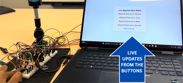
Figure 19: Setting the required PPE. (Source: Mouser Electronics)
- Sign in to the Employee Sign-In page (Figure 20) using your first and last name.
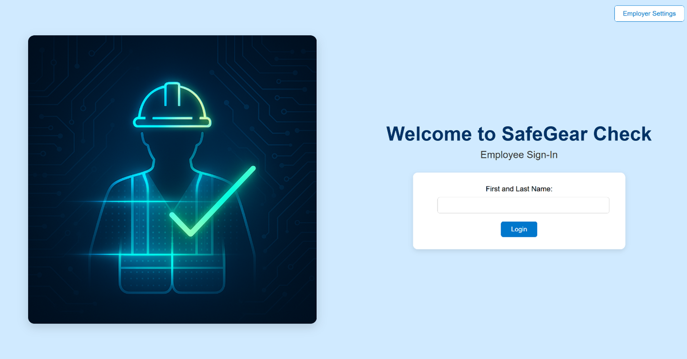
Figure 20: Employee Sign-In page. (Source: Mouser Electronics)
- Once you receive confirmation that you have signed in (Figure 21), click Start Safety Check. The proximity sensor should detect your presence and motion, triggering the yellow light to illuminate.
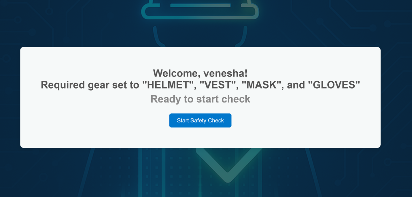
Figure 21: Start Safety Check page. (Source: Mouser Electronics)
- The Nicla Vision scans you, checking whether you are wearing all the PPE you selected on the Employee Settings page.
- If the Nicla Vision detects missing PPE, the red light illuminates (Figure 22), the speaker plays a “Missing Gear” audio message, and the web interface displays a “Missing Gear” message that itemizes the missing PPE (Figure 23).
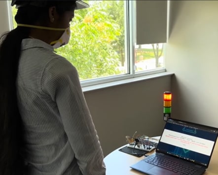
Figure 22: Red light, screen message, and voice message noting the missing PPE. (Source: Mouser Electronics)
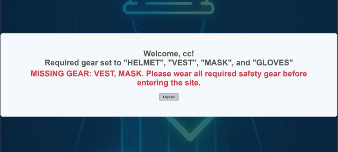
Figure 23: Missing gear message on web interface when worker is missing PPE. (Source: Mouser Electronics)
- If the Nicla Vision detects all required PPE, the green light illuminates (Figure 24), the speaker plays an “All Clear” audio message, and the web interface displays an “All Clear” message (Figure 25).
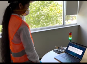
Figure 24: All Clear message, green light, and corresponding voice message when the required gear is detected. (Source: Mouser Electronics)
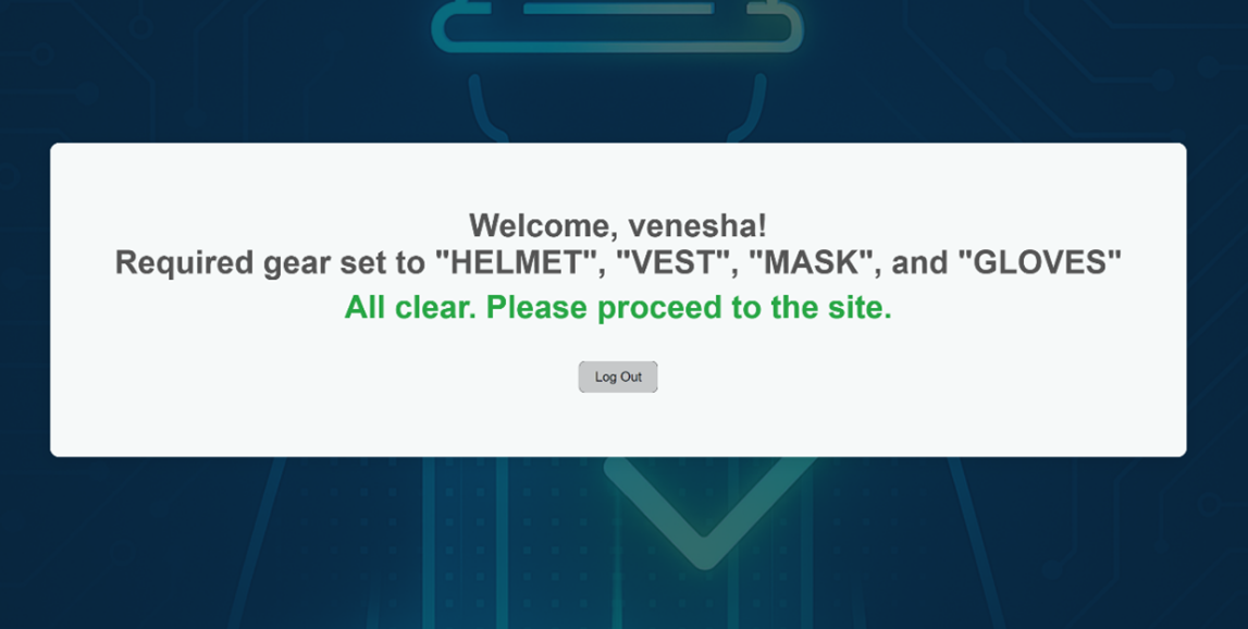
Figure 25: All Clear message on web interface when the required gear is detected. (Source: Mouser Electronics)
- Once you have received the “All Clear” message, click Log Out. The system will reset, allowing the next employee to sign in.
- The employees’ sign-in information and detection results are stored in the Systems_log.txt file (Figure 26).
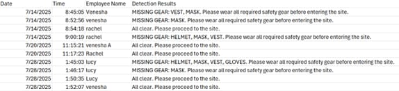
Figure 26: Date, time, employee name, and detection results in the system_log.txt file. (Source: Mouser Electronics)
Conclusion
The SafeGear Check project demonstrates how the Arduino Nicla Vision can effectively detect employees wearing the correct PPE to work in dangerous environments. Using a trained AI model from Edge Impulse, Nicla Vision can effectively identify the required PPE while also controlling external elements, such as a tower light and speaker, based on the detection results.
With the system’s web interface, employers can establish the required PPE, and employees can sign in to activate the detection system. SafeGear Check enables employers to ensure that employees are well-equipped and protected before entering hazardous environments, helping to decrease the number of workplace accidents.
Sources
[1]https://www.osha.gov/laws-regs/federalregister/1994-04-06