Building Deterministic Ethernet: A Hands-On Guide to TSN with the ADIN6310 Switch
Configure, Validate, and Compare Real-Time Performance Using VLAN Tagging, PCP Priority, and Time-Aware Shaping

Image Source: Grispb/stock.adobe.com
By Ricky Flores, Mouser Electronics
Published January 13, 2026
As industrial systems become more complex and time-critical, the limitations of conventional Ethernet are increasingly exposed. In applications such as robotic motion control, synchronized sensor networks, and industrial automation, even millisecond delays can lead to unacceptable results. To meet these demands, Time-Sensitive Networking (TSN) has emerged as a powerful extension to standard Ethernet.
TSN is a suite of IEEE 802.1 standards designed to enable deterministic, low-latency communication over Ethernet networks. By introducing features such as VLAN tagging (IEEE 802.1Q) for traffic prioritization and time-aware shaping (IEEE 802.1Qbv) synchronized via gPTP (IEEE 802.1AS), TSN ensures that critical packets are transmitted and received at precise, predictable times, every time, even under heavy network load.
These capabilities are essential in environments where real-time communication is non-negotiable. TSN enables multiple traffic classes to coexist on the same physical link while guaranteeing bounded latency for high-priority streams. For engineers designing the next generation of smart factories, autonomous vehicles, or synchronized control systems, mastering TSN is increasingly becoming a requirement, not a choice.
Project Materials and Resources
Project Bill of Materials (BOM)
- Analog Devices EVAL-ADIN6310EBZ Evaluation Board
- Ethernet cables (3)
- USB-A–to–Ethernet adapters (3)
- Unmanaged Ethernet switch
Other Hardware
- Windows 11 machine
- Linux (Ubuntu/Debian) machines (2)
Project Code/Software
- ADIN6310EVKSW Evaluation Software (Rev. 5.0.0)
- Wireshark
- iPerf3
- Tcpdump utility (if not included in Linux distribution)
Project Technology Overview
This hands-on project explores the real-world implementation and performance of TSN using the Analog Devices (ADI) EVAL-ADIN6310EBZ Evaluation Board (Figure 1), which serves as a pluggable TSN-capable switch. The setup includes three host machines: two running Linux and one running Windows.
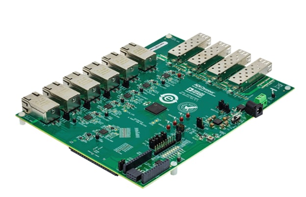
Figure 1: Analog Devices EVAL-ADIN6310EBZ Ethernet evaluation board. (Source: Mouser Electronics)
The Linux systems handle traffic generation and VLAN/PCP configuration, while the Windows machine is used solely for managing the ADIN6310’s TSN settings.
The project provides step-by-step instructions for the following tasks:
- Configure VLAN 10 on the two Linux machines
- Assign static IPs and set traffic priorities
- Use iPerf3 to generate high- and low-priority User Datagram Protocol (UDP) and Transmission Control Protocol (TCP) traffic
- Monitor packet flow using tcpdump and Wireshark
- Compare performance with and without TSN features enabled
- Evaluate the impact of traffic prioritization and TAS
Hardware Overview
The following are the key hardware components used in this project.
Analog Devices ADIN6310 Industrial Ethernet TSN Switch
At the core of this project is the ADI ADIN6310, a high-performance, six-port Gigabit Ethernet TSN switch designed specifically for industrial networking applications. Each port on the ADIN6310 can operate at configurable speeds and interfaces with external PHYs, such as the ADIN1100, ADIN1200, or ADIN1300, allowing flexible deployment across copper or fiber links. Its four SGMII/SerDes interfaces support backplane connectivity, SFP modules, and cascading between multiple switches. The architecture is optimized for low power and low latency, making it suitable for tightly synchronized applications.
In addition to TSN features, the switch includes hardware support for redundancy protocols such as Parallel Redundancy Protocol (PRP) and High-Availability Seamless Redundancy (HSR). These protocols offload redundancy management from the host processor, improving reliability without increasing system complexity.
USB-A–to–Ethernet Adapters
Three USB-A–to–Ethernet adapters were used in this project to provide Ethernet connectivity. While these adapters are not TSN-compliant, they allowed us to perform VLAN tagging and traffic-classification tests. Please note that these adapters may not be necessary for your machines; our Windows laptop lacked a built-in Ethernet port. Additionally, one of our Linux devices’ onboard network interface controllers (NICs) was over a decade old and did not support IEEE 802.1Q VLAN tagging or PCP markings, both of which are essential for TSN traffic classification.
Note that, in general, USB-to-Ethernet adapters are not TSN-compatible and cannot support features such as time synchronization or time-aware scheduling. They are suitable only for preliminary testing or demonstrations that focus on VLAN and QoS behavior, not full TSN validation.
Software Overview
This section introduces the software tools required to configure, generate, and analyze TSN traffic.
ADIN6310 TSN Switch Evaluation Software
The ADIN6310 Evaluation Software provides a graphical interface for configuring and evaluating the TSN capabilities of the ADIN6310 switch. It supports automatic discovery and management of up to 10 ADIN6310 or ADIN3310 devices connected via Ethernet and enables users to configure key features such as VLANs, PCP mapping, and scheduled traffic. The application includes a built-in web server and NETCONF server for each detected device, allowing configuration via web interface or YANG-based NETCONF clients. This tool serves as a bridge for users to familiarize themselves with switch operation before transitioning to the embedded driver library.
Note: At the time of writing, Rev. 5.0.0 was the current revision of this software. Since then, ADI has released Rev. 5.1.0-GA. Either version should function properly with this project.
iPerf3
iPerf3 is a widely used command-line tool for generating TCP and UDP traffic streams. It is used in this project to simulate deterministic and best-effort traffic and to measure throughput, jitter, and packet loss across the TSN-enabled network. By running targeted traffic between endpoints, iPerf3 helps quantify the performance benefits of TSN scheduling and prioritization under varying load conditions.
Wireshark
Wireshark is a powerful packet analysis tool for capturing and inspecting real-time network traffic. In this project, Wireshark is essential for validating VLAN tagging, PCP prioritization, and timestamp accuracy in TSN streams. It enables engineers to verify whether traffic is correctly tagged and prioritized as it passes through the ADIN6310 switch, ensuring compliance with IEEE 802.1Q and TSN protocols.
Developing the Project
The evaluation begins by assembling the hardware, installing the software, and setting up the devices.
Hardware Installation
This section describes how to connect the various hardware components for this project (Figure 2).
- Plug the 12V adapter into P2 on the eval board. Please note that some kits might come with a 9V wall adapter.
- Turn Switch S1 to the ON position. LED DS4 should light up.
- Plug one of the USB-to-Ethernet adapters into the Windows machine.
- Plug an Ethernet cable into that adapter and plug the other end into Port 0 on the eval board.
- Plug the second USB-to-Ethernet adapter into one of the Linux machines (sender).
- Plug an Ethernet cable into that adapter and plug the other end into Port 1 on the eval board.
- Plug the third USB-to-Ethernet adapter into the other Linux machine (receiver).
- Plug an Ethernet cable into that adapter and plug the other end into Port 2 on the eval board.
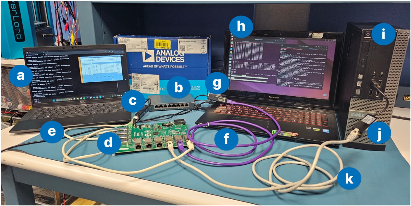
Figure 2: The hardware setup for this project: (a) Windows machine, (b) unmanaged switch, (c) USB-to-Ethernet adapter, (d) EVAL-ADIN6310EBZ eval board, (e) Ethernet cable, (f) Ethernet cable, (g) USB-to-Ethernet adapter, (h) Linux machine (sender), (i) USB-to-Ethernet adapter, (j) Linux machine (receiver), (k) Ethernet cable. (Source: Mouser Electronics)
Software Installation
The following steps outline the installation process for the software tools required for this project.
ADIN6310 Evaluation Software Rev. 5.0.0 (Rev. 5.0.0)
On the Windows machine, install and run the ADIN6310 TSN Switch Evaluation Software. The installer also provides options to repair or remove the software by rerunning the installer and selecting the desired action.
iPerf3
Both Linux systems are used for all traffic-generation and traffic-reception tests, including VLAN-tagged traffic, PCP prioritization tests, and baseline measurements.
Install iPerf3 on each Linux machine:
sudo apt update
sudo apt install iperf3
Verify the installation by running:
iperf3 --version
Wireshark
On the two Linux machines, run the following commands to install Wireshark:
sudo apt update
sudo apt install wireshark
Executing the Project
To ensure smooth communication between your Windows and Linux machines, we disabled the operating systems' firewalls to execute this project. Alternatively, you can configure port exceptions on both operating systems.
Note: Disabling the firewall entirely is recommended only in a controlled test environment. For production or secure systems, always add port-specific rules.
Disable Firewalls
In Windows, use the following steps (Figure 3) to disable the firewall:
- Open Windows Security.
- Select Firewall & network protection.
- Click on the active network (e.g., Private network).
- Set Microsoft Defender Firewall to Off.
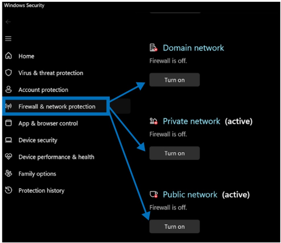
Figure 3: Windows 11 firewall settings. (Source: Mouser Electronics)
In Linux:
- Type sudo ufw status to check if the Linux uncomplicated firewall (UFW) is enabled.
- If UFW is enabled, type sudo ufw disable to disable it temporarily.
Linux VLAN and PCP Configuration
This section explains how to assign a static IP, create a VLAN interface, and verify that VLAN tagging is working correctly in Linux.
- Assign the base IP address (fallback mode)
You can assign a fallback/static IP address using either the graphical network settings or the command line.
- Option A: Using network adapter settings (GUI)
Navigate to your network adapter settings and manually assign a fallback IP address. In our setup, we used 192.168.1.2 (Figure 4) for the Linux sender and 192.168.1.3 for the Linux receiver.
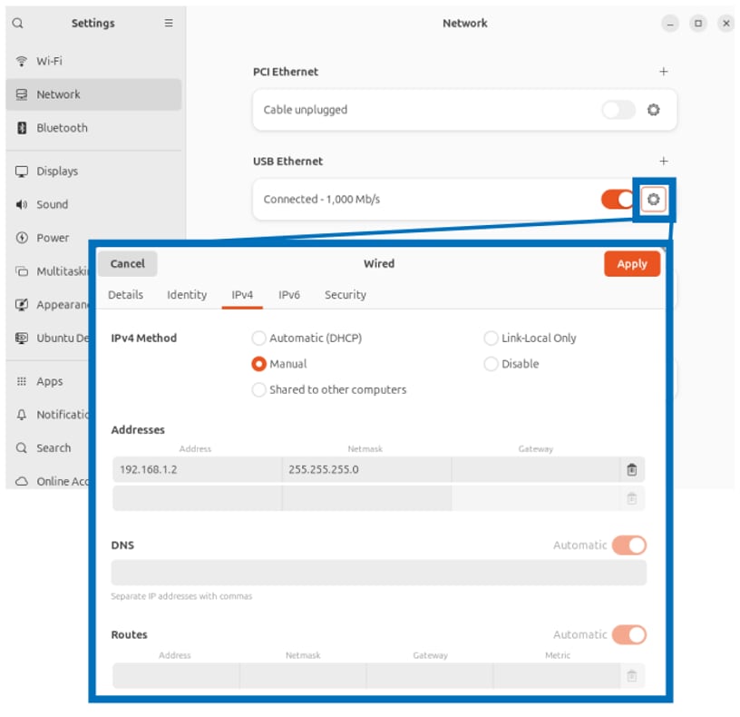
Figure 4: Assign a static IP in Linux. (Source: Mouser Electronics)
- Option B: Using the command line:
To identify your Ethernet device name, run sudo ip addr show on both the Linux sender and the Linux receiver. Look for the interface corresponding to your Ethernet adapter.
(In our project, the interface on the sender is enx8cae4ccd29a7, as highlighted in Figure 5.)
If you’re unsure which interface is the correct one, disable the adapter, run sudo ip link, then re-enable it and note which interface disappears and reappears.
Next, configure the interface on the Linux sender using the commands below, replacing <YOUR_DEVICE_NAME> with the correct adapter name for that device:
sudo ip addr flush dev <YOUR_DEVICE_NAME>
sudo ip addr add 192.168.1.2/24 dev <YOUR_DEVICE_NAME>
sudo ip link set <YOUR_DEVICE_NAME> up
Then, configure the interface on the Linux receiver using the commands below, replacing <YOUR_DEVICE_NAME> with the correct adapter name for that device:
sudo ip addr flush dev <YOUR_DEVICE_NAME>
sudo ip addr add 192.168.1.3/24 dev <YOUR_DEVICE_NAME>
sudo ip link set <YOUR_DEVICE_NAME> up
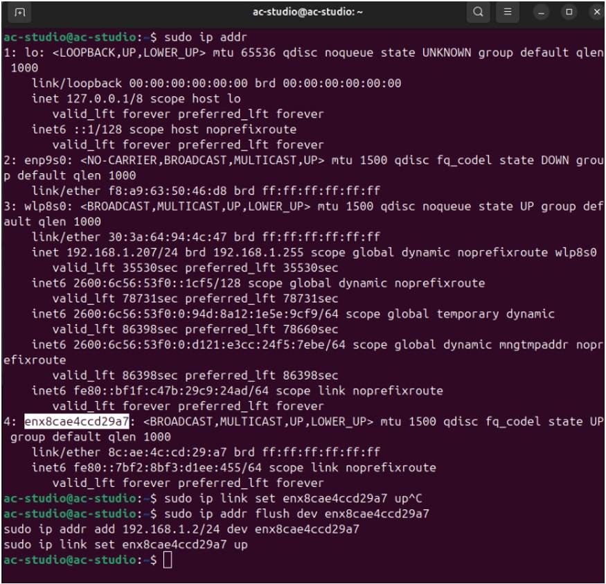
Figure 5: List of commands used to assign a static IP in the Linux sender. (Source: Mouser Electronics)
- Both Linux machines use a VLAN-tagged interface (VLAN ID 10). The receiver creates a standard VLAN interface, while the sender creates a VLAN interface and applies PCP settings for the outgoing traffic. Linux interface names are limited to 15 characters. If your base interface name is long (e.g., enx8cae4ccd29a7), use the code in the next step to create a shorter alias (e.g., vlan10).
- In the Linux machine acting as the receiver, enter the code below to create and configure a VLAN 10 interface. First, any existing interface named vlan10 is removed to prevent conflicts. The physical network interface is then assigned to a variable for easier reference. A new VLAN interface, vlan10, is created on top of the base NIC using VLAN ID 10, and an IP address is assigned to this VLAN interface. Finally, the interface is brought up to enable sending and receiving tagged traffic.
sudo ip link del vlan10 2>/dev/null
DEV=<YOUR_DEVICE_NAME>
sudo ip link add link $DEV name vlan10 type vlan id 10
sudo ip addr add 192.168.10.3/24 dev vlan10
sudo ip link set vlan10 up
You can confirm VLAN settings using:
ip -d link show vlan10
Note: Avoid assigning any other IP within the same subnet to VLAN 10, as it would mix tagged and untagged traffic and could lead to routing ambiguity.
- In the Linux machine acting as the sender, enter the code below to create a VLAN 10 interface and configure its PCP marking for outgoing traffic. This configuration ensures that Linux maps packet priorities to the correct VLAN PCP values, enabling proper traffic prioritization. The code first removes any existing VLAN interface and identifies the base network interface. It then uses egress-qos-map 0:0 7:7 to define how Linux socket buffer (SKB) priorities correspond to VLAN PCP values, mapping SKB priority 0 to PCP 0 and SKB priority 7 to PCP 7.
sudo ip link del vlan10 2>/dev/null
DEV=<YOUR_DEVICE_NAME>
sudo ip link add link $DEV name vlan10 type vlan id 10 egress-qos-map 0:0 7:7
sudo ip addr add 192.168.10.2/24 dev vlan10
sudo ip link set vlan10 up
- In the sender, enter the code below to apply PCP marking based on the UDP destination port on the sender. This code demonstrates how to use the clsact queuing discipline to manage outgoing traffic priorities. By applying tc filters that match specific UDP destination ports, you can assign different SKB (socket buffer) priorities, with UDP port 5201 mapping to priority 7 (PCP 7) and UDP port 5202 mapping to priority 0 (PCP 0). This ensures both traffic flows exit the same switch port while maintaining distinct priorities, allowing proper handling of high- and low-priority packets.
sudo tc qdisc del dev vlan10 clsact 2>/dev/null
sudo tc qdisc add dev vlan10 clsact
sudo tc filter add dev vlan10 egress protocol ip prio 1 u32 \
match ip dport 5201 0xffff action skbedit priority 7
sudo tc filter add dev vlan10 egress protocol ip prio 1 u32 \
match ip dport 5202 0xffff action skbedit priority 0
Configuring the ADIN6310EVKSW Evaluation Software
These instructions show how to launch the evaluation software and detect the connected board.
- Launch the ADIN6310EVKSW Evaluation Software.
- The software automatically detects available network adapters. However, if no adapters appear in the list, click Refresh Ethernet Network Adapters.
- Double-click the Ethernet adapter connected to the eval board.
- Click in the first row of the Ethernet Adapter column to assign the correct adapter to your ADI device. The GUI supports configuring multiple switches using either the same network adapter or individual adapters.
- Click Find and Configure SES Devices.
- A SES button turns green when the software recognizes a board (Figure 6).
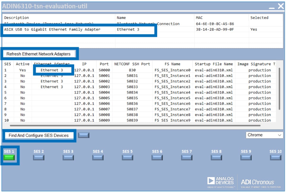
Figure 6: Set up the ADIN6310 Evaluation Software interface. (Source: Mouser Electronics)
On first launch, the application creates a local file system repository inside the FileSystemFolder folder (Figure 7).
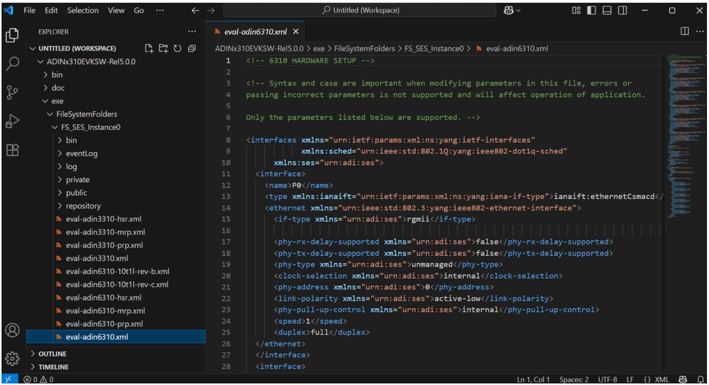
Figure 7: The directory containing the StartUpFileName xml file in the ses-configuration. (Source: Mouser Electronics)
Configuring the Board
The ADIN6310 Evaluation Software reads parameters from ses-configuration.txt (Figure 8), including the following:
- IP: 127.0.0.1 (loopback address)
- Unique port for each board (up to 10 supported)
- Folder location and XML config file
Each board starts with a default MAC address. The evaluation software assigns a unique MAC during configuration.
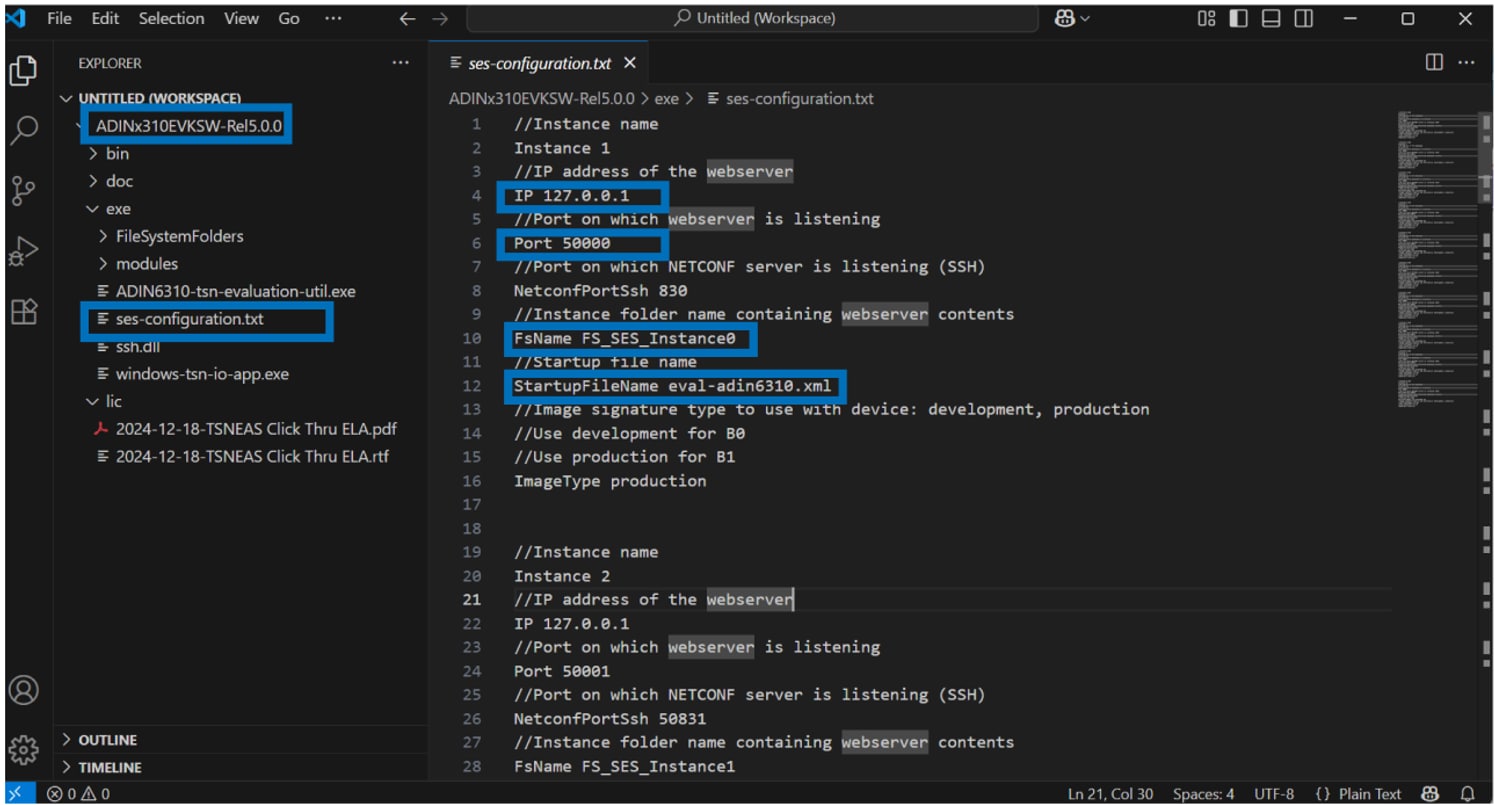
Figure 8: Configuration file used to initialize the ADIN6310 switch. (Source: Mouser Electronics)
Once the SES1 button turns green, only the first two Ethernet ports will remain lit (Figure 9). The RJ45 LEDs indicate active links, and since only two Ethernet cables are connected, only these two ports establish a link and light up.
Clicking the SES1 button opens the configuration webpage (the button will turn orange).
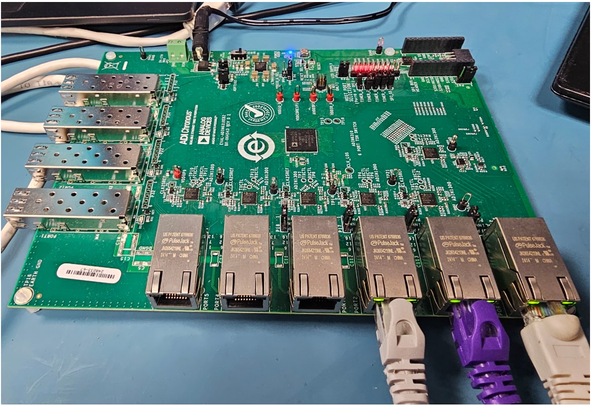
Figure 9: The ADIN6310 Evaluation Software detects the TSN switch and activates link indicators only on ports with active Ethernet connections on both ends. As shown, the LEDs on the three rightmost ports are illuminated, confirming successful link establishment. (Source: Mouser Electronics)
Managing Multiple Boards
The ADIN6310 Evaluation Software supports up to 10 simultaneous devices, each with a unique folder in FileSystemFolders. A background process (windows-tsn-io-app) launches automatically for each board. In this project, we connect only one board; when connecting more than one board, allow approximately one minute for each board’s repository to initialize. If you are daisy-chaining multiple boards, the software will try to find all connected boards. Once no more boards are found, an error message will appear (Figure 10).
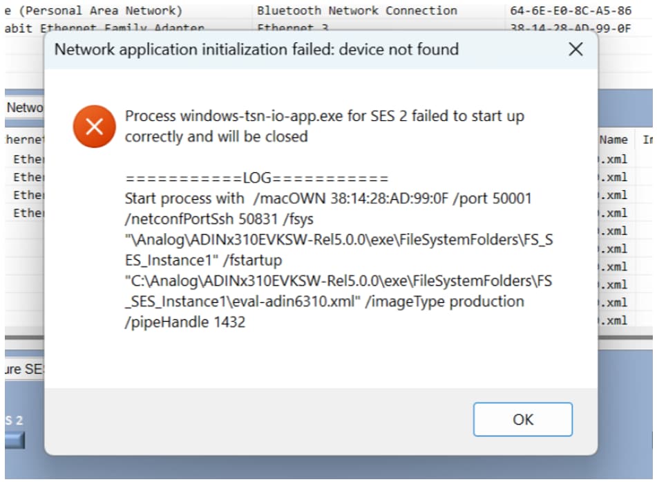
Figure 10: Expected error message that will appear when no more ADI switches are found in the ADIN6310 Evaluation Software interface. (Source: Mouser Electronics)
Troubleshooting Tips
If the LED doesn’t turn green within two minutes, close the evaluation software, power cycle the board, and try again.
When the boards are power-cycled, they revert to default MACs and may appear as new devices. To close old processes, press Ctrl and move the pointer to the Find And Configure SES Devices button. The button’s text will change to Close All Running Processes.
Configuring the Switch and Propagating VLAN
You can configure VLAN settings through the ADIN6310's web interface at http://127.0.0.1:5000. Here, you can assign VLAN IDs, set port modes, define priorities, and control VLAN propagation on each port. The configuration system uses a Candidate–Running–Startup model.
Use the tabs at the top of the interface (Figure 11) to switch between views.
- Candidate: Editable draft configuration
- Running: Active configuration applied to the switch
- Startup: Persistent configuration loaded at boot (must be saved separately)
- In the left menu, click VLAN Table.
- Set the VLAN ID for each port (e.g., 10).
- Choose the Port Mode (e.g., Learn & Forward).
- After making changes, click Save to store them in the Candidate
- Click Commit to activate the changes in the Running
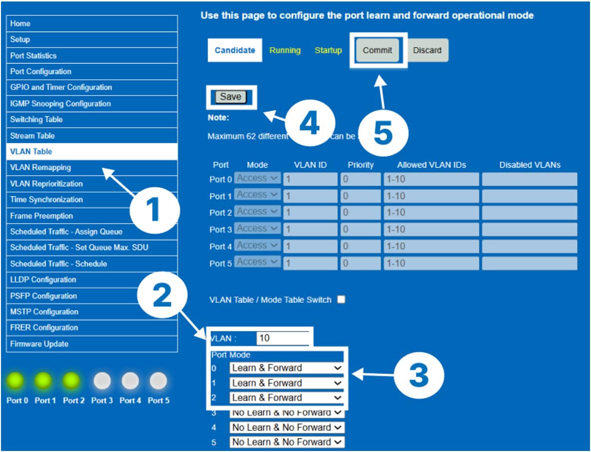
Figure 11: The web interface accessed via http://127.0.0.0:5000 contains settings that can be modified in the ADIN6310 switch. (Source: Mouser Electronics)
Verifying VLAN and PCP Tagging
Click the Running tab and ensure that port modes 0, 1, and 2 for VLAN 10 show as Learn & Forward (Figure 12).
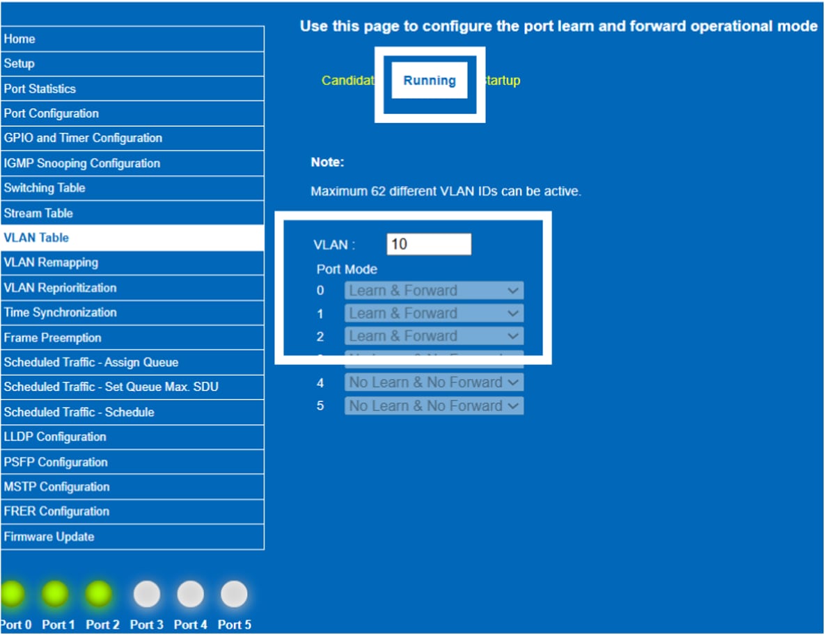
Figure 12: Verify the changes were committed and successfully run on the ADIN6310 switch. (Source: Mouser Electronics)
Packet Inspection with Tcpdump
To verify VLAN tagging and PCP priority values during the tests, packet captures were performed on both Linux machines, the sender and the receiver. This allows inspection of both the VLAN interface (vlan10) and the underlying physical network interface.
In a separate terminal on both Linux machines, type sudo wireshark, and then select the network you want to monitor (Figure 13).
Figure 13: Wireshark interface on Linux (sender) showing all networks with traffic. (Source: Mouser Electronics)
In Wireshark on both Linux machines, type “VLAN” to search only for VLAN traffic (Figure 14).
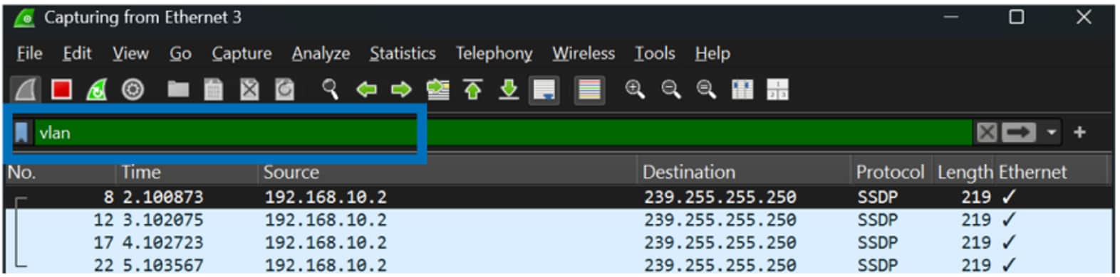
Figure 14: Wireshark interface showing how to filter VLAN traffic. (Source: Mouser Electronics)
Now that Wireshark can see VLAN tags on both machines, run this command on the Linux sender:
sudo tcpdump -i vlan10 -e -vvv
This shows the VLAN packets the computer has already sorted into the VLAN 10 box.
Alternatively, run the command below, which shows the actual packets on the network cable going in and out of the computer, including the VLAN tags.
sudo tcpdump -i <YOUR_DEVICE_NAME> -e -vvv
Results
- Captures were taken from both the VLAN interface (vlan10) and the underlying physical interface on each Linux machine.
- VLAN ID 10 was correctly detected in the 802.1Q header.
- Multicast and unicast UDP traffic appeared correctly tagged across both sender and receiver.
- Ethernet, IP, and UDP headers were properly encapsulated, confirming correct transmission through the ADIN6310 switch using VLAN tagging.
Traffic Prioritization and VLAN PCP Testing
To evaluate priority handling on the ADIN6310 TSN switch, two simultaneous UDP streams are generated from the sender to the receiver. Both streams exit through the same switch egress port, creating real queue contention.
Sender – Run Both Streams
# Best-effort traffic (PCP 0)
iperf3 -c 192.168.10.3 -u -p 5202 -B 192.168.10.2 -b 700M -t 60 -l 1200 &
# High-priority traffic (PCP 7)
iperf3 -c 192.168.10.3 -u -p 5201 -B 192.168.10.2 -b 280M -t 60 -l 1200
The two traffic flows combine to approximately 980 Mb/s, close to line rate.
Initializing iPerf3 Servers
To simulate concurrent traffic flows, initialize two iPerf3 servers on the Receiver:
iperf3 -s -p 5201 -B 192.168.10.3
# new terminal
iperf3 -s -p 5202 -B 192.168.10.3
Results
During the dual-stream test, the ADIN6310 consistently demonstrated clear and deterministic priority behavior. When both UDP flows were sent simultaneously, with approximately 280 Mb/s marked as PCP 7 (Figure 15) and approximately 700 Mb/s marked as PCP 0, the high-priority stream showed almost no packet loss across all five runs, typically ranging from 0 to around 200 lost packets (Figure 16). In contrast, the best-effort PCP 0 stream experienced approximately 0.15 percent packet loss (around 5,700 packets), and this behavior remained consistent each time the test was executed (Figure 17).
This result aligns exactly with how a TSN switch is expected to operate. Because both flows exit through the same physical egress port, they compete for the same transmit pipeline and queueing resources. The ADIN6310 applies IEEE 802.1Q strict-priority scheduling, which means that packets tagged with PCP 7 are always transmitted first. Only when the high-priority queue is empty does the switch serve PCP 0 traffic. Under near line-rate load, the best-effort queue naturally becomes the point of pressure, so any required drops occur only in the PCP 0 traffic while PCP 7 continues to flow with minimal disruption.
Another reason the results experience low packet loss is the ADIN6310’s per-port buffer architecture. Each switch port has its own dedicated frame buffer, rather than using a shared memory pool as many unmanaged switches do. As a result, congestion at one port does not affect traffic on another, and high-priority traffic flowing in the opposite direction has no impact on best-effort traffic in the forward direction. This design ensures that priority handling is deterministic and isolated, which is why the PCP 7 flow remained stable even during contention.
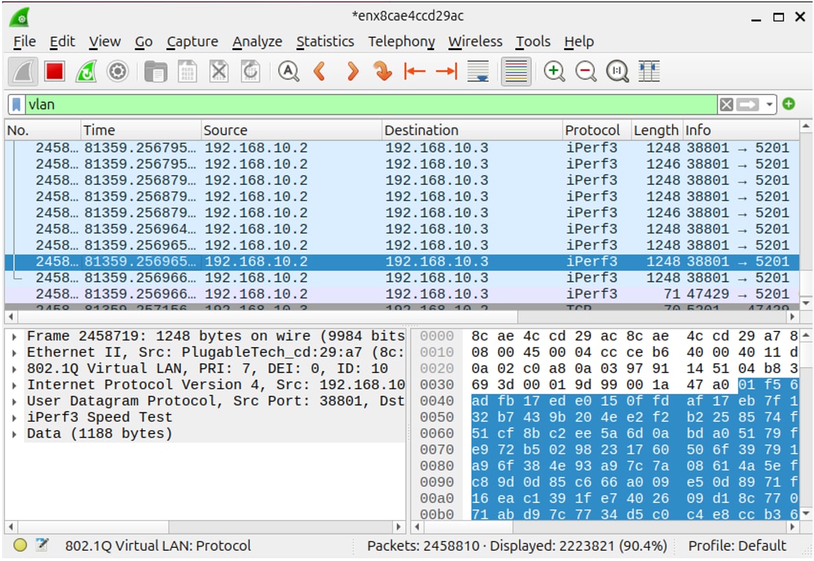
Figure 15: The Linux sender successfully transmits VLAN 10 traffic with PCP 7 using a USB-to-Ethernet adapter, verifying TSN priority marking. (Source: Mouser Electronics)
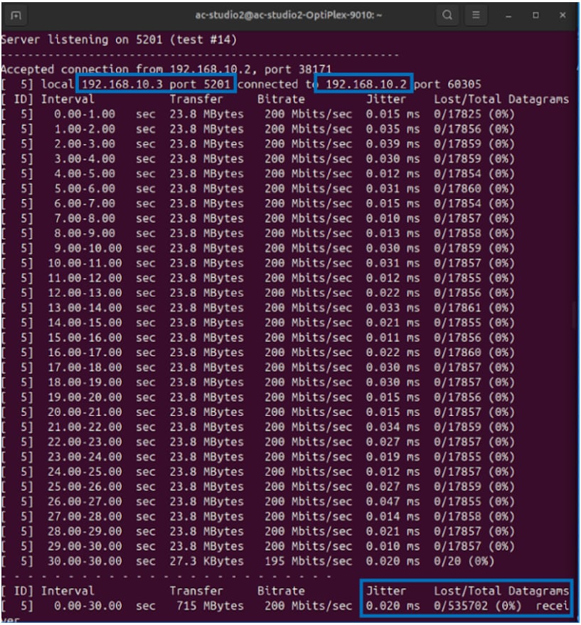
Figure 16: The ADIN6310 switch prioritized UDP traffic from the sender machine tagged with PCP 7, resulting in minimal jitter and zero packet loss. (Source: Mouser Electronics)
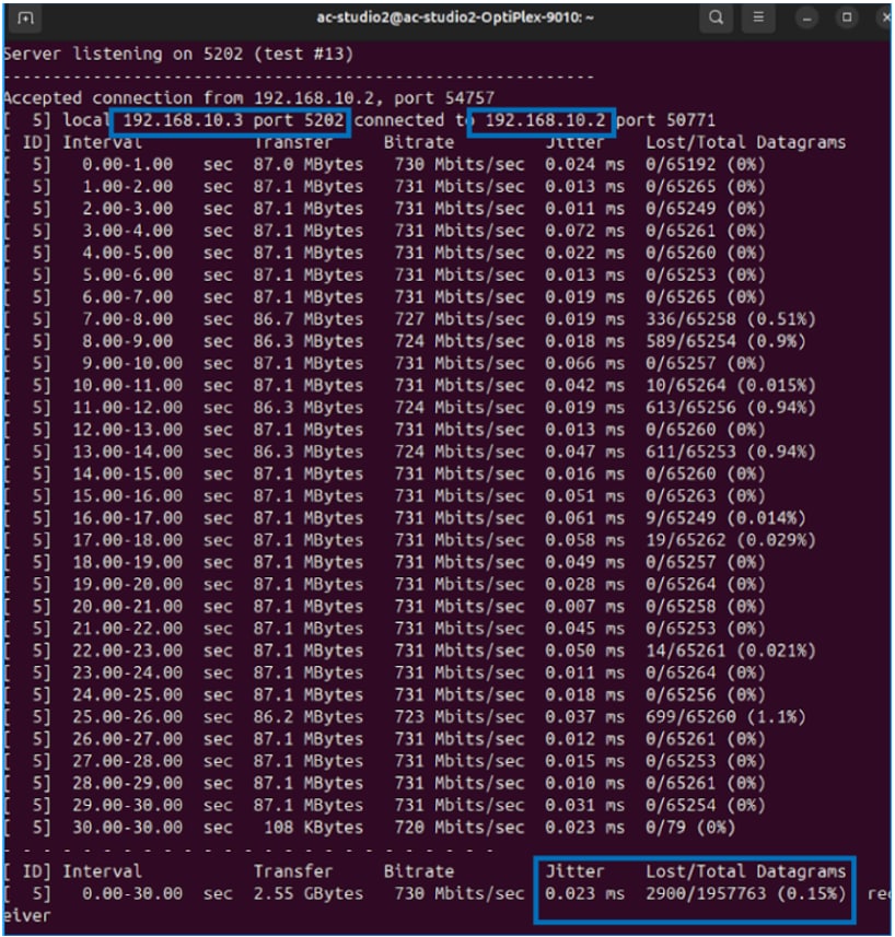
Figure 17: Traffic from the sender machine tagged with PCP 0 experienced higher jitter and some datagram loss due to a lack of prioritization. (Source: Mouser Electronics)
Debugging Tips
USB bandwidth limitations
Some USB-to-Ethernet adapters automatically fall back to USB 2.0 mode, which has a maximum theoretical bandwidth of 480 Mb/s and typically delivers ~300 Mb/s in practice. When both transmit and receive traffic share this link, iPerf3 may appear capped at around 150 Mb/s. Ensuring the adapter is connected to a USB 3.0 port (5 Gb/s) resolves this bottleneck.
NIC driver behavior on Windows (if sending traffic from Linux to Windows)
Although this project uses two Linux machines for traffic generation and reception, we also tested Windows-to-Linux traffic during early measurements. In those mixed-OS tests, we observed that Windows occasionally produced inconsistent high-rate UDP throughput due to NIC driver behavior and buffering differences. These effects can cause iPerf3 to report much lower send rates than the configured bitrate.
If your setup involves Windows as one of the iPerf3 endpoints, be aware that UDP performance may be limited by the Windows network stack or driver implementation, especially at near–line-rate traffic. In such cases, testing with Linux at both endpoints can help determine whether the bottleneck is OS-related rather than network-related.
Can’t ping the 2 Linux machines?
If you can't establish connectivity between the two Linux machines (e.g., ping fails), try resetting the network configurations on both systems. (Figure 18):
- Open Settings and select Network from the left menu.
- Under USB Ethernet, click the gear icon.
- In the dialog box that opens, click Remove Connection Profile.
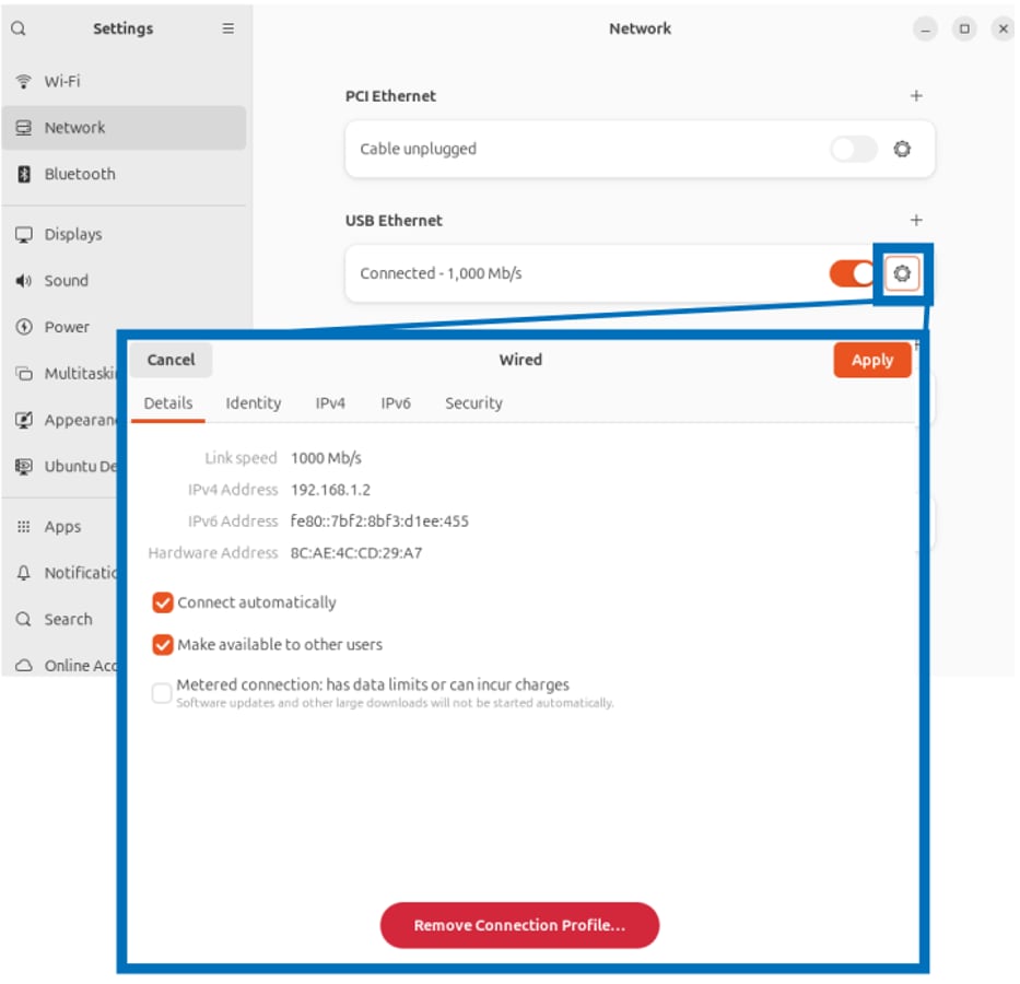
Figure 18: If necessary, remove a network adapter to reset network configurations in Linux. (Source: Mouser Electronics)
Additionally, restarting the iPerf3 server/client processes and power-cycling the ADIN6310 board often resolves persistent communication issues by reinitializing interfaces and clearing any stale settings.
Testing on an Unmanaged Switch
This section describes how to repeat the traffic test using a basic unmanaged switch to create a baseline for comparison. The goal is to observe how the same network load behaves without TSN features such as VLAN tagging or traffic prioritization (Figure 19).
Connect the two Linux machines exactly as follows:
- Sender: connects its Ethernet cable to Port 1 of the unmanaged switch
- Receiver: connects its Ethernet cable to Port 2 of the unmanaged switch
Only these two devices are used in the unmanaged-switch scenario. The ADIN6310 evaluation board and the Windows machine are not part of this test.
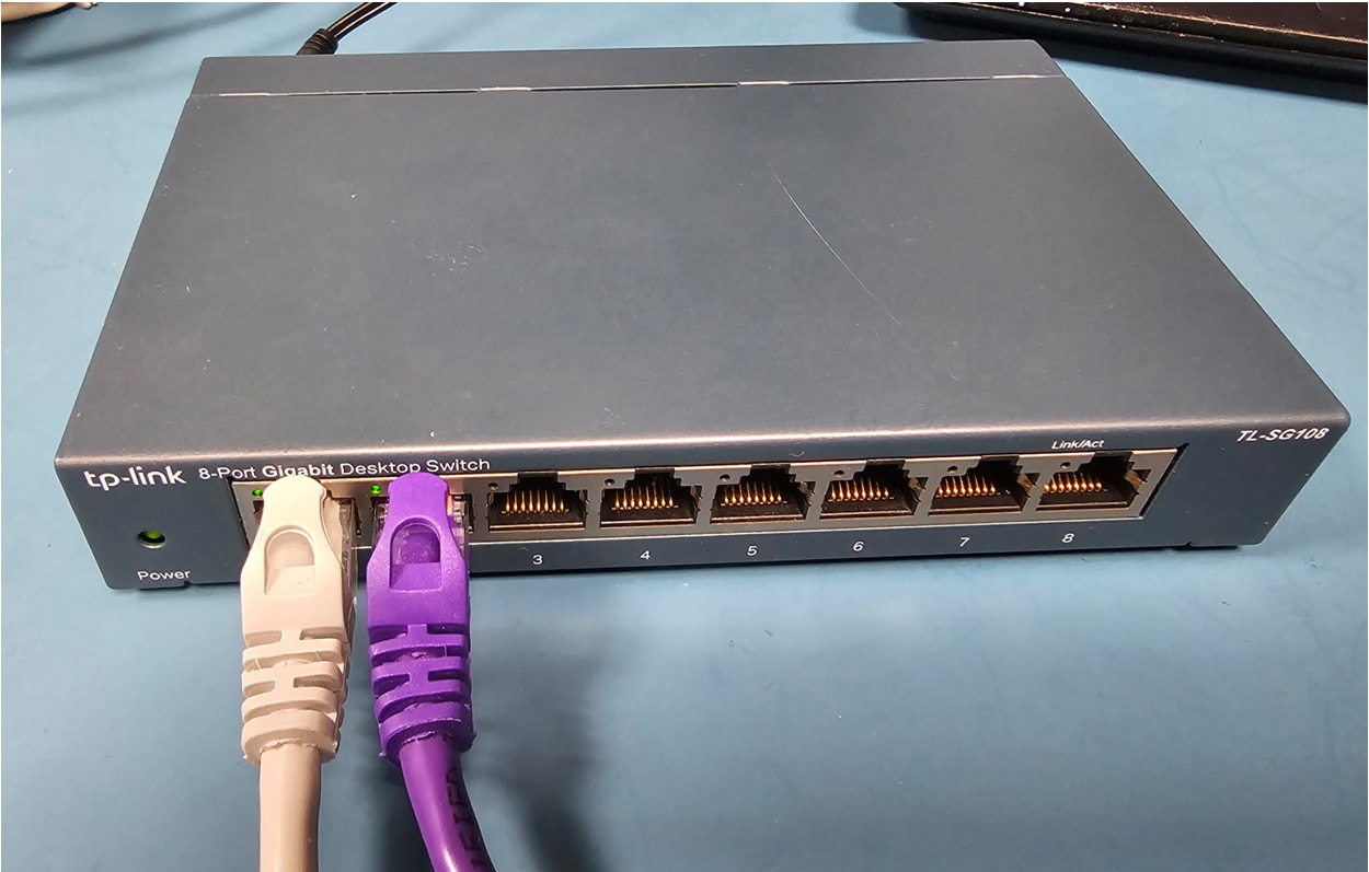
Figure 19: Unmanaged switch used for testing traffic without TSN prioritization. (Source: Mouser Electronics)
Remove VLAN Configuration
Because this baseline test is intended to run without VLAN tags or priority information, both Linux systems must operate on their plain Ethernet interfaces.
On each Linux machine, remove any previously created VLAN interface:
sudo ip link delete vlan10 2>/dev/null
After this, each machine uses its normal network interface (e.g., enx… or eth0), and both systems must remain in the same subnet (for example, 192.168.10.x).
iPerf3 Tests
Open two terminals on Linux B and run:
iperf3 -s -p 5201
New terminal:
iperf3 -s -p 5202
These two servers will receive the same dual-stream traffic pattern used in the TSN test.
From the sender, run the same combined 980 Mb/s traffic load as before, but this time it will not have VLAN tags or PCP values:
# Best-effort stream #1
iperf3 -c <Receiver-IP> -u -p 5202 -b 700M -t 60 -l 1200 &
# Best-effort stream #2
iperf3 -c <Receiver-IP> -u -p 5201 -b 280M -t 60 -l 1200
Both streams now have identical priority and no tags.
Tip: Replace <Receiver-IP> with your sender’s IP address (for example, 192.168.1.2).
Results
When the unmanaged-switch test was executed, the results differed significantly from the ADIN6310 test.
Because no VLAN tags were used in this scenario, both streams were forwarded as standard best-effort traffic, regardless of the switch’s internal capabilities. This ensures a neutral comparison where neither stream receives priority treatment.
Under this configuration:
- Packet loss appeared in both flows (Figure 20).
- The stream that experienced more loss varied from run to run.
- Jitter and delay were less predictable.
- No consistent priority behavior emerged.
- This inconsistency is expected in a non-TSN environment where both traffic streams share the same queue and are forwarded using simple best-effort logic.
It is important to note that the purpose of this test is not to evaluate the TP-Link switch itself. Instead, it provides a baseline showing how traffic behaves when no prioritization mechanism is present. When compared against this baseline, the ADIN6310’s TSN features, including strict priority queuing, clearly demonstrate how time-sensitive PCP-7 traffic remains protected even as the link approaches saturation.
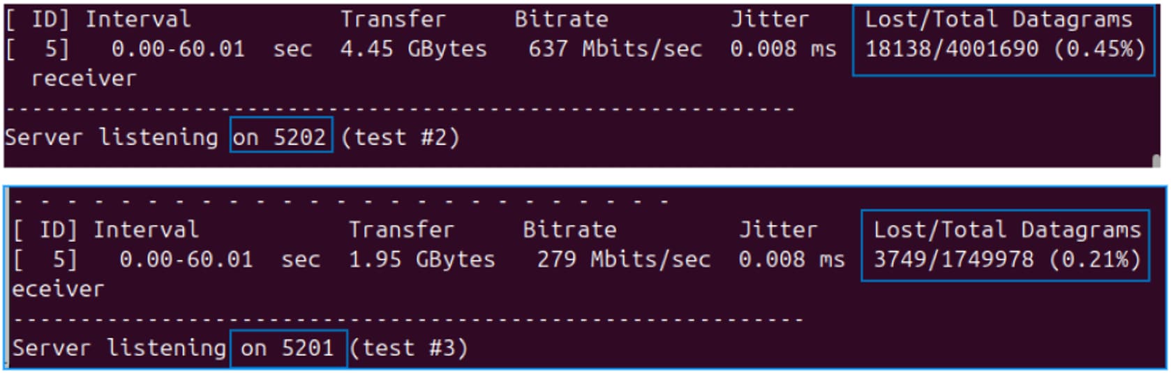
Figure 20: Comparison of packet loss using a non-TSN switch, showing inconsistent behavior with packet loss. The same test was performed five times, and similar results were observed. (Source: Mouser Electronics)
VLAN Reprioritization
To test the ADIN6310 switch's VLAN reprioritization feature, modify the default PCP mapping by remapping PCP 0 to PCP 5. This allows you to confirm that the ADI switch is automatically reclassifying incoming priority 0 traffic as priority 5 (Figure 21).
- Access the VLAN reprioritization menu.
- In the left sidebar, click VLAN Reprioritization.
- Ensure you are in the Candidate
- For each desired port, select the Enable Reprioritization
- In the VLAN Priority 0 row, set Remap priority to 5. Modify other VLAN priorities (i.e., PCP values) 1–7 as needed.
- Click Save Port [#] under each port you modified, then click the global Save at the bottom of the screen.
- At the top of the screen, click Commit to apply changes from Candidate configuration to Running This enables the new priority mappings in real time.
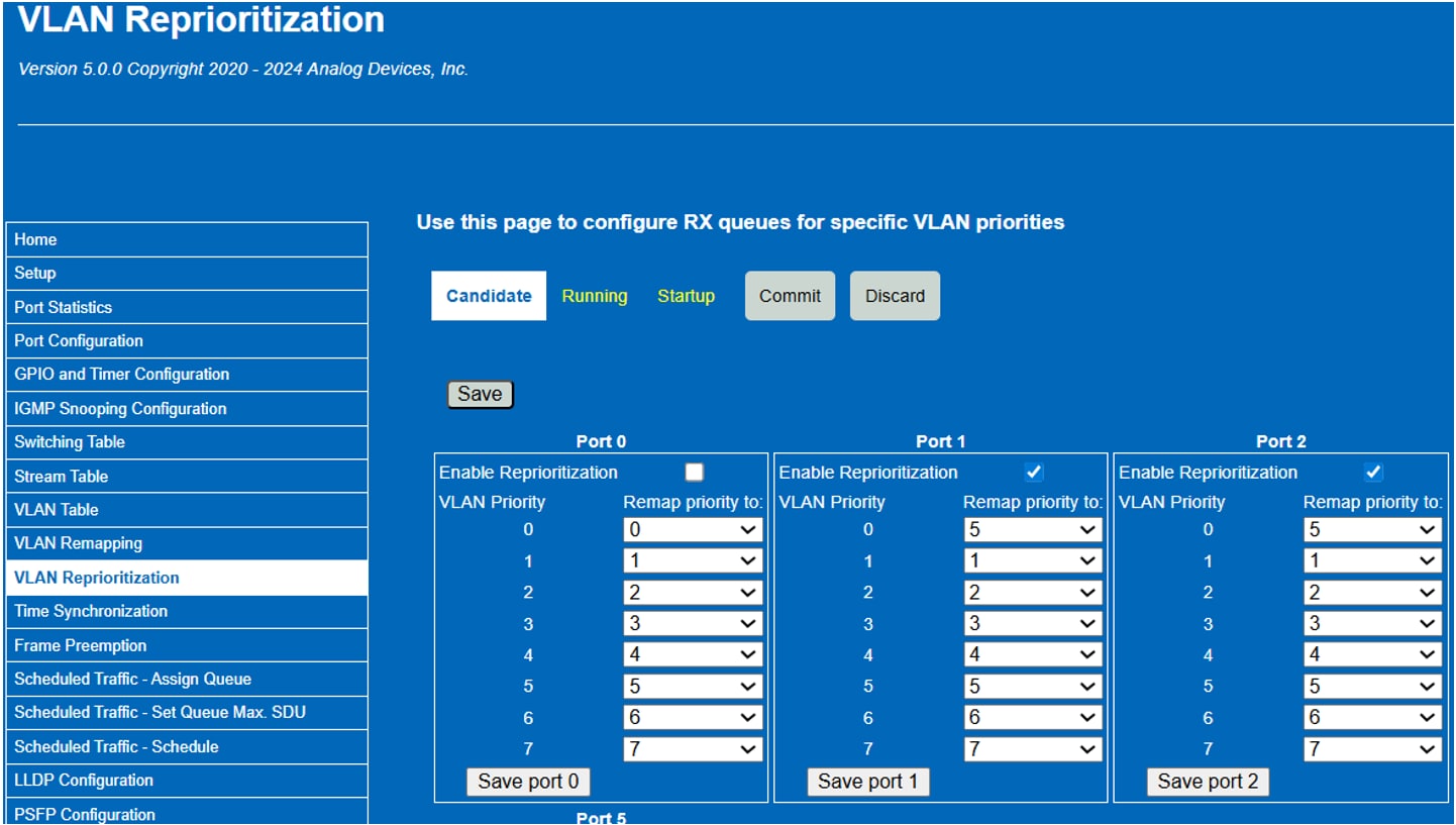
Figure 21: This interface shows the steps to configure VLAN Reprioritization on Ports 1 and 2. Frames tagged with VLAN priority 0 are automatically remapped to priority 5. (Source: Mouser Electronics)
- Verify with Wireshark (Figure 22) by capturing packets before and after the switch. You should see that traffic initially tagged with PCP 0 now appears as PCP 5 after passing through the ADIN6310.
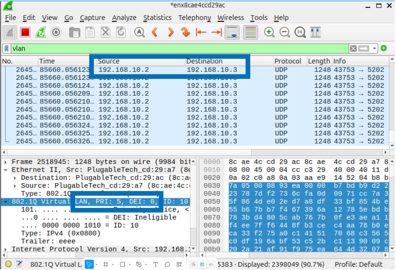
Figure 22: VLAN-tagged traffic sent by the Linux sender and captured after the ADIN6310 switch by the Linux receiver shows a PCP value of 5, confirming that the ADIN6310 switch dynamically elevated the priority from PCP 0. (Source: Mouser Electronics)
Scheduled Traffic (TAS)
The ADIN6310 TSN switch supports TAS to control egress queues based on a synchronized gate schedule. In this configuration, we enabled scheduling on Port 1 and Port 2 (Figure 23 (a)), using a 1ms cycle time set by Cycle Time Numerator = 1 and Denominator = 1000. This defines a periodic loop where gate states repeat every millisecond, which is suitable for real-time industrial applications.
Our gate schedule consisted of two entries for both ports (Figure 23 (b)):
- Entry 0 (100,000 ns)
- Entry 1 (900,000 ns)
In Figure 23, Entry 0 keeps all gates open while Entry 1 closes them, allowing all queues to transmit for a brief 100 µs window before halting traffic for the remainder of the 1 ms cycle. This configuration is not typical in a production environment. It only serves as a simplified demonstration to verify TAS functionality, clearly showing that traffic flows only when the gates are open and stops immediately once they close.
We tested the effect of the gate state settings using iPerf3. When all queues were enabled, UDP traffic was transmitted successfully. However, when we deselected the bit 7 (queue 7) leftmost checkbox in Port 1 (the queue used for our high-priority TSN traffic), iPerf3 continued running, but no packets were transmitted, as the closed gate prevented egress from that queue. This behavior confirms that gate configuration directly controls whether traffic can exit the port. Similarly, deselecting the checkboxes for all gate states halted all traffic, further verifying TAS behavior.
Although traffic was blocked at the port level, Wireshark on Linux still showed correct VLAN PCP tags (e.g., PCP 7), because tagging occurs at the source before hitting the switch. This confirms that tagging and scheduling are independent of each other. The switch does not alter tags but determines whether traffic is transmitted based on the gate state at the scheduled time.
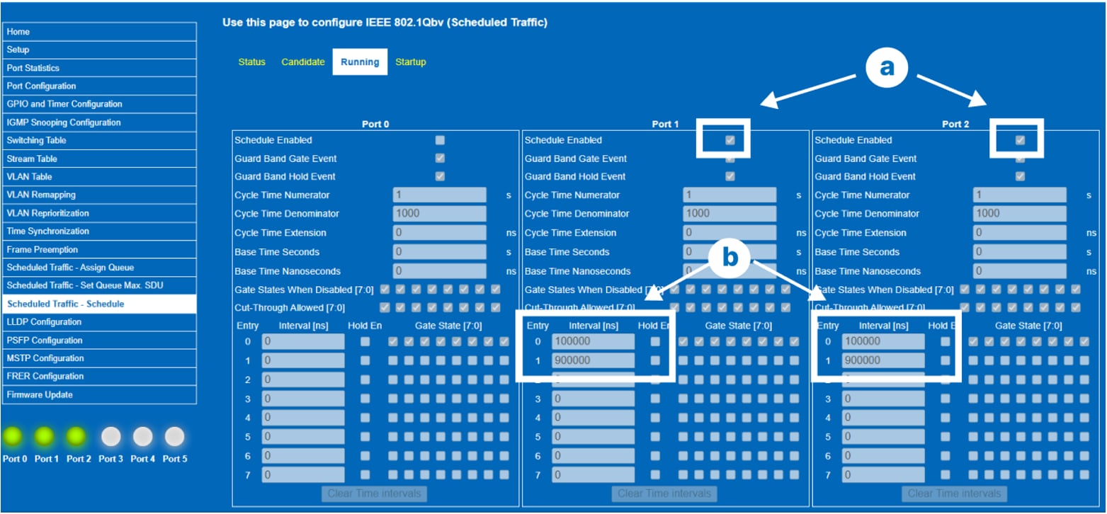
Figure 23: Scheduled traffic configuration on Ports 1 and 2, showing a 1ms schedule cycle with selective gate control for prioritized queue transmission. (Source: Mouser Electronics)
Conclusion
This project demonstrates how the ADIN6310 enables Time-Sensitive Networking (TSN) with reliable, low-jitter delivery of high-priority traffic compared to a non-TSN baseline. Using VLAN tagging, PCP prioritization, and controlled traffic generation between two Linux systems, we validated the switch’s TSN behaviors in a controlled setup. The results highlight how strict-priority queuing on the ADIN6310 protects critical traffic even under near–line-rate load, while best-effort traffic yields as expected. These findings underscore the importance of proper interface configuration, VLAN handling, and switch-side scheduling for industrial applications such as robotics, motion control, and real-time automation, where deterministic Ethernet performance is essential.