Modular Design with Floating Board-to-Board Interconnects
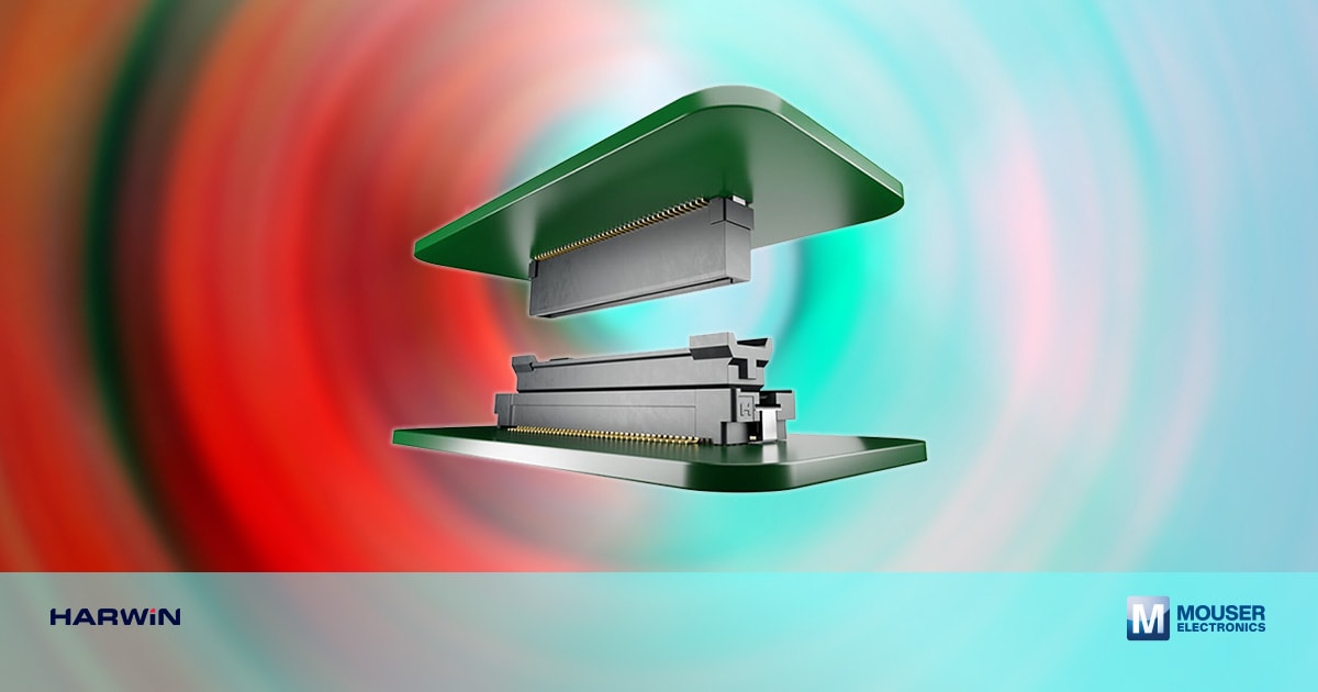
Image Source: Mouser Electronics
By Ryan Smart, VP of Product, Harwin
Design is a multi-faceted challenge. Not only are engineers expected to deliver products with higher performance and more features in ever-smaller form factors, they must also complete designs in short timeframes. Also, there is a growing need for designs to be manufactured at high speeds without compromising quality or operational reliability during product lifetime.
Meeting these requirements affects both the design process and the materials and components selected. Modular design, for example, has become more popular, allowing key sub-sections (such as I/O, processor, and analog signal processing) to be built onto separate boards that can be reused across several products. This reduces design risk and development time. However, careful consideration needs to be given to how to connect the various modular boards.
Single or Multiple Connectors
Using a single connector between boards is simple but can cause noise, crosstalk, and long trace issues. Multiple fine-pitch connectors improve signal separation and reduce trace lengths but require extremely precise PCB alignment. Even sub-millimeter misalignment—caused by manufacturing tolerances—can stress connectors, leading to damage, lower production yield, and reduced reliability in the field.
Mitigating Misalignment with Floating Connectors
A special type of board-to-board connectors have been developed to address these challenges. So-called 'Floating' connectors derive a degree of elasticity from a combination of a housing that can move laterally and longitudinally and a novel contact design featuring a spring-like mechanism. In this type of connector, the housing is suspended by the contacts, which are usually housed in the male half of the connector.
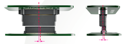
Figure 1: Floating connectors can accommodate misalignment during automated manufacture (Source: Harwin)
The degree of two-directional movement afforded by this arrangement generally exceeds the potential misalignment that can occur as a result of the manufacturing process. This movement allows pick-and-place processes to be deployed for boards with multiple connectors in cases where the sum of misalignments might, otherwise, present challenges for high-speed, high-precision mating. As a result, designers can focus on design rather than manufacturing requirements, leaving them free to deploy multiple floating board-to-board connectors per board pair. Decisions about the type and quantity of connectors can be based purely upon the needs of the circuit rather than any limits associated with interconnects.
The spring-based 'suspension' mechanism inherent in floating connectors will also contribute to connection integrity during operation, not least in applications that encounter some levels of vibration or shock, whether it be the daily use of a portable device, the operation of a moving vehicle, or a factory automation system. For example, floating connectors can mitigate the possibility of performance degradation or failure from 'fretting', when long-term vibration causes the plating to wear from rigid mating pins, exposing the underlying alloy to potential oxidation.

Figure 2: Innovative contact design provides benefits in floating connectors (Source: Harwin)
While floating connectors can be used universally, many applications remain where normal board-to-board connectors are more than adequate. In assessing which technology is more appropriate for a particular application, designers should consider the following:
- Would the design benefit from multiple connectors per board pair?
- What is the mechanical accuracy of the automated manufacturing process?
- How much will the final product be exposed to shock and vibration during normal use?
- How often will the boards be separated and replaced during the product's lifetime?
The answers to these questions should guide the designer as to which path to take.
The connector selection process should also consider the environmental aspects, especially the operating temperatures to which the connector may be exposed. This is particularly relevant for designs enclosed to protect sensitive electronics and where temperature changes can contribute to stress on connectors, especially if the materials differ or there are differences in board thicknesses.
Finally, it should be noted that almost all applications will require that the connector be made from materials that are fully RoHS-compliant, as well as free of REACH SVHCs (Substances of Very High Concern), lead, brominated flame retardants, red phosphor (PFOS/PFOA), or antimony.
Floating Connector Developments
Today's designers can choose from product families that offer a variety of connector pitches, usually in the sub-millimeter (0.5mm to 0.8mm) range, and contact counts up to and beyond 160 per connector. Options for vertical and horizontal female connectors allow boards to be connected parallel to each other or at right angles, while a broad spectrum of mounting heights down to as little as 6mm allows engineers to choose solutions that meet the inter-board space requirements of increasingly compact form factors.
Harwin has expanded its Flecto family of floating connectors, which are well-suited for high-performance applications with multiple micro-pitch interconnects. The mating area of the male connector can move by up to ±0.8mm from the centerline.
Among the latest advances have been the launch of connectors that support data rates up to 12Gbit/s, allowing them to deliver the performance expected by standards such as SAS (Serial Attached SCSI), which is widely used in enterprise server and storage applications. At the same time, technologies that mix signals and power in a single connector will support applications where traces need to carry heavier currents.
Along with their inherent spring-like structure, many of the latest floating connectors offer further support for accurate alignment and robust interconnects through location pegs (which eliminate movement during solder reflow) and retention tabs (which provide additional mechanical strength).
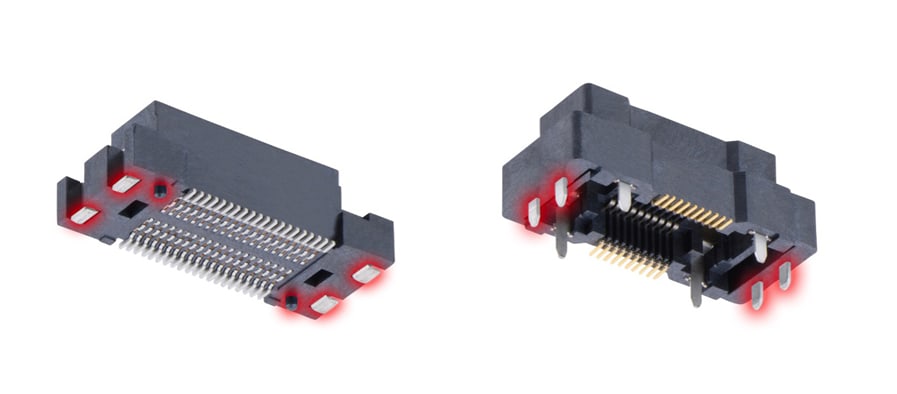
Figure 3: Retention tabs and through-board pins enhance the mechanical rigidity of floating connectors (Source: Harwin)
Conclusion
Early consideration of methods for connecting pairs of PCBs is essential. The right interconnect choice will ensure an optimised product compatible with modern production processes that can enhance reliability during lifetime operation in the field. In particular, the use of floating connectors that accommodate and absorb misalignments and small movements in multiple axes is becoming much more prevalent across various applications, ranging from industrial automation to electric vehicles and security systems to IoT devices.
Author
 Ryan Smart is Vice President of Product at Harwin, where he drives innovation and leads new product development. With over a decade in electronic components, he takes products from concept to launch, empowering engineers with cutting-edge connectivity solutions.