Connecting Renesas EK-RA6M3 to Medium One IoT Cloud

Image Source: Zapp2Photo/Shutterstock.com
By Greg Toth for Mouser Electronics
Published September 1, 2020
The Renesas EK-RA6M3 Evaluation Kit enables users to evaluate features of the RA6M3 MCU and develop prototype IoT applications with internet connectivity. The Medium One Internet of Things (IoT) Platform is a cloud-based IoT platform designed to help early-stage developers prototype IoT projects or connect existing hardware to the cloud. In this project, we’ll set up an IoT development environment using the EK-RA6M3 board to read a temperature and humidity sensor and send the data to the Medium One cloud through the internet to be processed and viewed using programmable workflows and configurable widget dashboards.
Project Materials and Resources
The project bill of materials lists components used in this project. Additional hardware and software development tools are also identified.
Project Bill of Materials (BOM)
- 968-K7EKA6M3S00001BU - Renesas EK-RA6M3 Evaluation Kit
- 932-MIKROE-2101 - Mikroe SHT click Temperature and Humidity Sensor
- 349-M1IOTPROTO – One-year subscription to the Medium One cloud environment
Hardware
- Personal computer (PC) running Microsoft Windows®
- USB Type A to Mini-B cable (included with EK-RA6M3)
- Ethernet LAN with Internet connectivity and DHCP server
- RJ-45 Ethernet patch cable (included with EK-RA6M3)
Accounts and Software
- Web browser for accessing software download sites and Medium One IoT Platform
- Login account for the Medium One IoT Platform
- Renesas e2 studio Integrated Development Environment (IDE)
- Renesas Flexible Software Package (FSP)
- Application project files available in a GitHub repository
- Serial terminal program such as Tera Term on the PC
Project Technology Overview
Renesas EK-RA6M3 Evaluation Kit
The Renesas EK-RA6M3 Evaluation Kit (Figure 1) provides a flexible development board for evaluating features of the Renesas RA6M3 MCU group. The onboard RA6M3 microcontroller features a 120MHz Arm® Cortex®-M4 core with 2MB code flash, 640KB SRAM, and various I/O peripherals, including GPIO, Ethernet controller, DMA, USB, CAN, SCI, SPI, I2C, A/D and DAC, capacitive touch sensing, and TFT controller/2D accelerator/JPEG decoder. The board has an Ethernet jack, USB high-speed and full speed host and device, 32MB external QSPI flash, multiple 5V input sources, onboard debugger, three user LEDs, and two user pushbuttons. Four types of ecosystem connectors provide standardized expansion capabilities, including MikroElektronika™ mikroBUS, Digilent Pmod™ (SPI and UART), Seeed Grove® I2C, and Arduino Uno R3. Four sets of 40-pin headers provide direct access to the native MCU pins for easy testing and debugging.
More detailed information about the kit can be found here and here.

Figure 1: Renesas EK-RA6M3 Evaluation Kit (Source: Mouser Electronics)
Mikroe 2101 SHT click Temperature and Humidity Sensor
The SHT click (Figure 2) is a sensor board containing a Sensirion SHT31 temperature and humidity sensor. The sensor is read digitally through an I2C bus, and the board plugs into the EK-RA6M3 mikroBUS connector. We'll use this as the main sensor for this project.
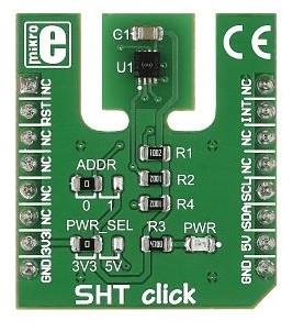
Figure 2: Mikroe SHT click Sensor Board (Source: Mouser Electronics)
Renesas e2 studio
Firmware programs that run on microcontrollers are typically developed and tested using an Integrated Development Environment (IDE) running on a personal computer. The IDE provides an editor, compiler, linker, debugger, and a mechanism for transferring binary program images to the microcontroller.
The EK-RA6M3 can be programmed using Renesas e2 studio, an Eclipse-based IDE that runs on Windows computers. It connects to the EK-RA6M3 using a USB cable that supports programming and debugging. e2 studio can be downloaded for free from the e2 studio site.
Renesas Flexible Software Package (FSP)
The Renesas Flexible Software Package provides a quick and versatile way to build secure connected IoT devices using the Renesas RA family of Arm microcontrollers. FSP provides various modular software components, including production-ready peripheral drivers, FreeRTOS and middleware stacks, Ethernet and Wi-Fi connectivity, TCP/IP and MQTT protocol stacks, USB middleware support for CDC, HID and Mass Storage Classes, secure connections through Mbed TLS, Arm PSA Cryptographic APIs and integrated hardware acceleration support, file systems, graphics processing, capacitive touch, and hardware drivers for a wide range of input/output peripherals.
Project Application Source Code Files
For this project, e2 studio was used to create a set of project source code files that have been modified and extended to work with the Medium One IoT Platform. The resulting files have been put in a GitHub repository that you can download and use for this project. The project files will be imported into e2 studio, where they'll be compiled and programmed onto the EK-RA6M3 board. The project files consist of a main application program and supporting functions for I/O and cloud connectivity.
Medium One IoT Platform
The Medium One IoT Platform (Figure 3) is designed to help early-stage developers prototype their IoT project or connect their existing hardware to the cloud. It offers an IoT Data Intelligence platform enabling customers to quickly build IoT applications with less effort. Programmable workflows allow you to quickly build processing logic without having to create your own complex software stack. Configurable dashboards allow you to visualize application data and view real-time data in various formats. Medium One’s iOS and Android apps will enable you to build simple mobile app dashboards to communicate with your devices through the IoT platform.

Figure 3: Medium One IoT Platform (Source: Mouser Electronics)
IoT devices can exchange data with Medium One through either a REST API or MQTT. More detailed information about the Medium One IoT Platform can be found here and on the Medium One site.
The Setup (Hardware)
While setting up the hardware, be sure to remember that electronic components are static-sensitive, so handle accordingly.
Personal Computer (PC)
Power up the personal computer and allow it to boot up.
Ethernet LAN
Make sure your Ethernet LAN has an active connection to the internet and a DHCP server that assigns IP addresses. The internet connection should allow MQTT communications to pass through without being blocked by a firewall.
EK-RA6M3 Evaluation Kit
On the EK-RA6M3 product info page, find the EK-RA6M3 Quick Start Guide and follow it to set up your board and development software. The main steps will include:
- Connecting the main board to your computer using the USB cable.
- Running the quick start example project.
- Downloading and installing e2 studio IDE, libraries, and example projects using the Flexible Software Package (FSP) bundle available via the "Download the Latest FSP" button on the Renesas FSP
- Customizing the quick start example project using e2 studio.
- Setting up the debug connection between the mainboard and your PC.
- Downloading and running the quick start example project using e2 studio.
Mikroe 2101 SHT click Temperature and Humidity Sensor
Unplug the EK-RA6M3 USB cable, so the board is disconnected and powered off. Unbox the SHT click and plug it into the EK-RA6M3 mikroBUS connector making sure the pin numbers match up correctly. Reconnect the USB cable to your PC.
Ethernet LAN Connection
Connect the EK-RA6M3 board to your Ethernet LAN using the RJ-45 patch cable.
The Setup (Software)
e2 studio
The EK-RA6M3 quick start guide explained how to download and install e2 studio on your PC. After going through those steps and importing the quickstart project, your e2 studio IDE should look similar to Figure 4.
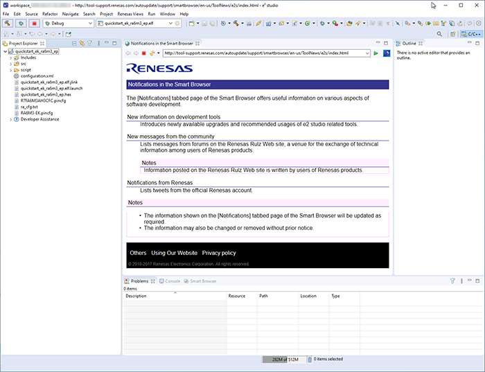
Figure 4: e2 studio With Quickstart Project Loaded (Source: Mouser Electronics)
Download and Open the Project Application Source Code files
Web browse to the GitHub repository https://github.com/Mouser-Electronics/ma17_files and find the EK_RA6M3_MQTT_Eth_MediumOne_1.0.0.zip file. Download that file to your computer, but do not unzip it.
In e2 studio, select File > Import… and then General > Existing Projects into Workspace, then click Next. Checkmark Select archive file and click Browse… to pick the EK_RA6M3_MQTT_Eth_MediumOne_1.0.0.zip file you downloaded from GitHub. Make sure the EK_RA6M3_MQTT_Eth_MediumOne_NOTLS project is check-marked and then click Finish. After a successful import, the Project Explorer window should look like Figure 5.
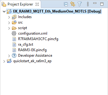
Figure 5: After Importing the Project Into e2 studio (Source: Mouser Electronics)
We'll come back to the source code files later after setting up Medium One.
Set Up the Medium One IoT Cloud
Web browse to the Medium One IoT Platform and log in, after which you should see an initial dashboard resembling Figure 3. If you have trouble logging in, check your Medium One credentials to make sure you're using the latest URL provided with your subscription. Click Setup > Manage Users > Add New User. Set Username to mydevice, create a password of your choosing and enter it in both password fields, then click Save. In the Manage API Users list, you should see a new user account having Login ID = mydevice and an auto-generated user MQTT ID like Figure 6.
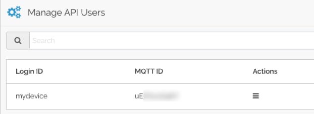
Figure 6: Newly created User ID (Source: Mouser Electronics)
Click Setup > MQTT, and you should see a Project MQTT ID and a set of port numbers like Figure 7.
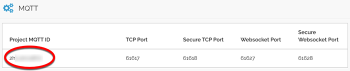
Figure 7: Project MQTT ID (Source: Mouser Electronics)
Medium One uses MQTT usernames and passwords for authentication. The MQTT username is created by combining the Project MQTT ID, a forward slash, and the user MQTT ID. For example, if the Project MQTT ID is “ZHxxxxxxx0Y” and the user MQTT ID is “sTxxxxxxx8w” the corresponding MQTT username would be “ZHxxxxxxx0Y/sTxxxxxxx8w”.
Next, we’ll create the MQTT password. Navigate to Setup > Manage API Keys > Add New API Key. Set the description to mydevice, make sure Enabled is check-marked, and click Save. The result should look like Figure 8.
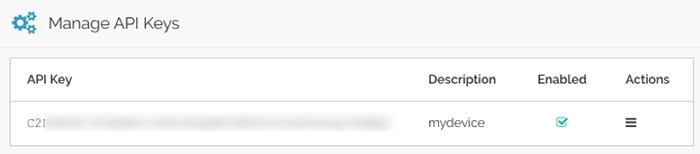
Figure 8: Newly created API Key (Source: Mouser Electronics)
The MQTT password is created by combining the API Key, a forward slash, and the mydevice user password. For example, if the API Key is “PZxxxxxxxxxxxxxxxxxxxxxxxxxxxxxxxxxxxxxxxxxxxMBQ” and the mydevice user password is “AaaaBbbb3” the corresponding MQTT password would be “PZxxxxxxxxxxxxxxxxxxxxxxxxxxxxxxxxxxxxxxxxxxxMBQ/AaaaBbbb3”.
The MQTT topic has the following format: “0/Project MQTT ID/User MQTT ID/Device ID”.
The Device ID field can be anything, and we’ll use "mydevice" as the Device ID. For example, if the Project MQTT ID is “ZHxxxxxxx0Y” and the user MQTT ID is “sTxxxxxxx8w” the corresponding MQTT topic would be “0/ZHxxxxxxx0Y/sTxxxxxxx8w/mydevice".
The MQTT username, MQTT password, and MQTT topic strings will be added to the project source code in the next step.
Update Application Source Code Files for Medium One Account Parameters
In e2 studio, expand the EK_RA6M3_MQTT_Eth_MediumOne_NOTLS project and open file src/medium_one.h. Find these string constants and set them to your own Medium One MQTT username, password, and topic strings as described earlier:
- clientcredentialMQTT_BROKER_USERNAME
- clientcredentialMQTT_BROKER_PASSWORD
- MQTT_TOPIC_PREFIX
Save the modified file and build the project. Verify the code compiles without errors. If you see compilation errors, check the changes you make to the source files. Note that the default project compilation settings have many categories of warnings enabled, so you'll likely see warnings during compilation of the FSP library files.
Run the Application
Make sure the EK-RA6M3 board is connected to the PC through the J10 DEBUG USB connection. Right-click on the EK_RA6M3_MQTT_Eth_MediumOne_NOTLS project under Project Explorer and select Debug As > Renesas GDB Hardware Debugging. In the pop-up dialog boxes that follow, select J-Link ARM and then R7FA6M3AH. Switch to the e2 studio Debug perspective and select Window > Show View > Other… > Debug > Renesas Debug Virtual Console. This will allow you to view printf() messages generated by the application.
At this point, the program should be loaded on the EK-RA6M3 board and paused in the debugger. Click the resume button (green arrow button in toolbar) one or more times to get the program running.
At this point, the EK-RA6M3 board should be running and periodically measuring temperature transmitted to Medium One through MQTT. The virtual debug console should show status messages being generated by the application.
How the Application Program Works
The high-level program flow includes:
- Initialize the board and sensor.
- Initialize the Ethernet connection and get an IP address via DHCP.
- Connect to Medium One MQTT broker. Note that this application as currently configured uses MQTT without TLS encryption, so the username, password, and sensor data are transmitted over the internet without encryption.
- Periodically read the temperature and humidity sensor and send data messages to Medium One MQTT broker.
MQTT Payload Format
MQTT messages are formatted as JSON strings according to the Medium One MQTT payload specification. Here’s an example message:
{"event_data":{"iteration":10,"timestamp":49104,"temp":71.26,"humid":52.31}}
Fields:
- iteration = counter that increments by 1 for each event_data message
- timestamp = milliseconds since board started
- temp = temperature in degrees F
- humid = relative humidity percentage from 0 to 100
Try heating or cooling the temperature sensor to see the data values change.
View Data in the Medium One Dashboard
In the Medium One dashboard, navigate to Data Viewer > Data Streams and click raw Events. You should see raw messages (Figure 9) being received. Click the “+” sign to view message details.
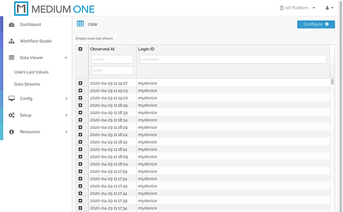
Figure 9: Raw message display (Source: Mouser Electronics)
Click Dashboard on the top left, then click Add Widget > Single User Real Time Events Stream to add an event stream widget to the dashboard.
In the Select user dropdown, select mydevice. You should now see messages appearing in the Real Time Events Stream widget (Figure 10). Click the dashboard save icon in the upper right corner to save your modified dashboard.
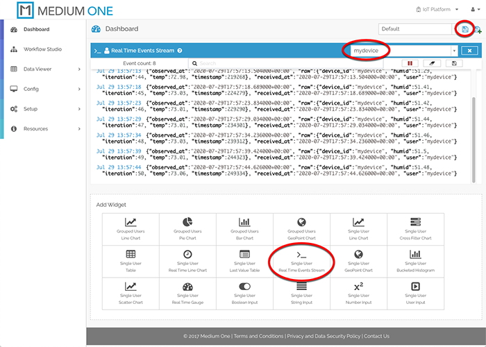
Figure 10: Real Time Events Stream Widget Display (Source: Mouser Electronics)
Add More Widgets
To display more widgets, we need to enable specific data fields contained in the message payload. Navigate to Config > Data Streams and click on raw Events. The Schema Map should be pre-populated with fields detected in the incoming messages, however, they are currently disabled. Check-mark the Active box on raw.humid, raw.iteration, raw.temp, and raw.timestamp, then click Save Data Stream. These fields are now available for use in other dashboard widgets.
Back on the dashboard, click the Single User Last Value Table widget and select the mydevice user within the widget. Click the widget’s Tag Config icon to the right of the mydevice user selection and check-mark raw:humid, raw:iteration, raw:temp and raw:timestamp, then click Save. The Last Value Table should now populate with the most recent received values for each field (Figure 11). Click the dashboard save icon toward the upper right corner to save the updated dashboard.
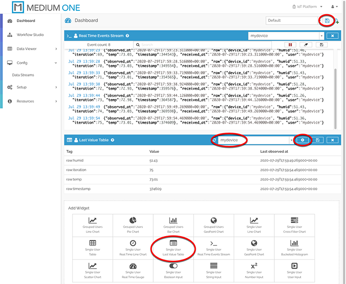
Figure 11: Last Value Table Widget Display (Source: Mouser Electronics)
Now let’s add dashboard widgets for the temperature, humidity, and iteration counter. Click Single User Real Time Gauge and select the mydevice user. Click the widget’s Tag Config icon and check-mark raw:humid, raw:iteration and raw:temp, then click Save. The updated dashboard should look like Figure 12. Click the dashboard save icon to save the updated dashboard. Try heating or cooling the temperature sensor to see the gauge values change.
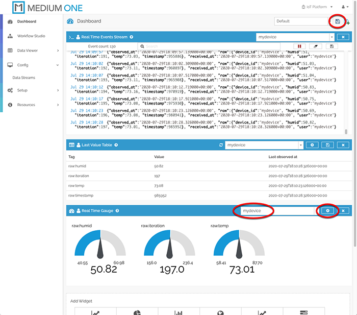
Figure 12: Real Time Gauge Widgets added to dashboard (Source: Mouser Electronics)
At this point, your board is running continuously, periodically reading the temperature and humidity sensor and transmitting data measurements to the Medium One cloud through the internet. Remember to power off the board when you’re done, otherwise, it will continue to send messages to Medium One and consume daily message allotments.
Troubleshooting Tips
- Make sure you've verified basic board operation as described in the quick start guide.
- Make sure e2 studio and Flexible Software Package (FSP) are installed and configured according to the instructions.
- Make sure you've set the correct Medium One parameters in your source code.
- Examine the informational messages generated by the application code in the Renesas Debug Virtual Console pane within e2 studio.
- Single-step through the code using the e2 studio debugger.
Conclusion and Where to Go Next
This project created an end-to-end sensor-to-cloud application that sends real-time sensor data to the Medium One IoT Platform. It can be modified and extended in a number of ways, and here are a few examples:
- Dive deeper into the application code and board hardware by reading the Renesas user guides and studying the source code.
- Explore other Renesas Flexible Software Package example projects.
- Add more widgets to the Medium One dashboard, such as a real-time line chart of temperature readings.
- Read other sensors on the Renesas EK-RA6M3 board or connect new sensors and include the data in messages sent to Medium One.
- Learn about the Medium One Workflow Studio, which lets you create data processing workflows to transform your sensor data.
- Experiment with the Medium One mobile apps.