How to Use Maxim Integrated Boards to Prototype Pulse Oximetry

Image Source: elenabsl/Shutterstock.com
By Greg Toth for Mouser Electronics
Published November 16, 2020
The Maxim Integrated MAX32620FTHR is a rapid development platform for quickly implementing battery-optimized solutions using the MAX32620 Arm® Cortex®-M4 microcontroller with a floating-point unit. When paired with a Maxim Integrated MAX30101WING pulse oximetry board, they provide a prototyping platform for taking heart rate and pulse oximetry measurements. The Medium One IoT Platform is a cloud-based Internet of Things (IoT) platform designed to help early-stage developers prototype IoT projects or connect existing hardware to the cloud.
In this project, we'll set up an IoT development environment using these boards and Medium One to collect heart rate and pulse oximetry data and send it to Medium One, where it can be processed and viewed using programmable workflows and configurable dashboard widgets.
Project Materials and Resources
The project BOM lists components used in this project. Additional hardware and software development tools are also identified.
Project Bill of Materials (BOM)
- 700-MAX32620FTHR# - Maxim Integrated MAX32620FTHR Feather Board
- 700-MAX30101WING# - Maxim Integrated MAX30101WING PulseOx FeatherWing Module
- 485-3619 - Adafruit HUZZAH32 ESP32 Feather Board with Stacking Headers
- 485-2886 - Adafruit Feather 12-pin and 16-pin Female Header Set
- 349-M1IOTPROTO – 1-year subscription to the Medium One cloud environment
Hardware
- 11 b/g/n Wi-Fi access point with a DHCP server, internet connectivity, and without a firewall or proxy that blocks outgoing traffic to the Internet
- Personal computer (PC) running Microsoft Windows®, MacOS or Linux
- USB Type A to Micro-B cable
Accounts and Software
- Web browser for accessing software download sites and portals
- Login account for the Medium One IoT Platform
- Mbed Online Compiler
- Free Mbed account for using the Mbed Online Compiler
- Application project files available in a Mbed code repository and a GitHub repository
- Arduino IDE for configuring the HUZZAH32 board
- Serial terminal program such as Tera Term on the PC
- Wi-Fi access point connection details including SSID and password
Project Technology Overview
Maxim Integrated MAX32620FTHR Feather Board
The MAX32620FTHR board is a rapid development platform to help engineers quickly implement battery-optimized solutions using the Maxim Integrated MAX32620 Arm® Cortex®-M4 microcontroller with a floating point unit. The MAX32620 MCU has 2048KB flash, 256KB SRAM, and various input/output peripherals, including USB, Serial Peripheral Interface (SPI), I2C, Universal Asynchronous Receiver/Transmitter (UART), 1-Wire, analog-to-digital converter (ADC), and General Purpose Input/Output (GPIO). The board features a MAX77650 power management controller and lithium polymer (LiPo) battery charger along with a MAX17055 fuel gauge for monitoring battery levels, allowing the board to be powered from either USB or battery sources. Two RGB indicator LEDs and two pushbuttons provide onboard indicators and user input.
Other sensors and I/O devices can be interfaced with the MAX32620FTHR through expansion connectors, including Feather-compatible board headers and two 12-pin Pmod™-compatible connectors.
Software development is supported using Mbed development tools or the Arduino IDE development environment. Code libraries are available for board initialization, input/output, and various processing functions to accelerate application development.
More detailed information about the MAX32620FTHR can be found here and here.
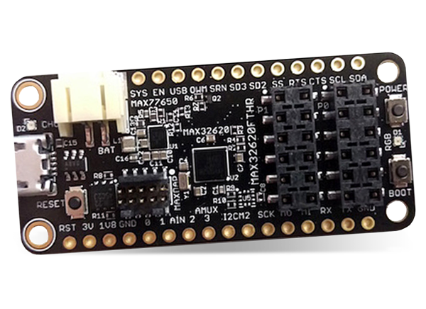
Figure 1: Maxim Integrated MAX32620FTHR Evaluation Kit for the MAX32620 (Source: Mouser Electronics)
Maxim Integrated MAX30101WING Pulse Oximeter FeatherWing Module
The MAX30101WING# is a rapid development board using the MAX30101 optical pulse oximetry sensor. It has a Feather-compatible pinout, which allows it to be directly connected to the MAX32620FTHR microcontroller board. The onboard MAX30101 sensor is a non-invasive reflective LED solution with an integrated glass cover. When combined with processing algorithms, the sensor can measure pulse rates and blood oxygen levels. The sensor features programmable sample rates and LED current for power savings. Power is controlled by the onboard MAX14750A power management chip, which sets the LED drive voltage and is programmable through an I2C interface.
More detailed information about the MAX30101WING can be found here and here.
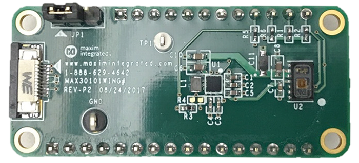
Figure 2: Maxim Integrated MAX30101WING Expansion Board (Source: Maxim Integrated)
Adafruit HUZZAH32
For this project, we'll use an Adafruit HUZZAH32 board to provide Wi-Fi connectivity and secure MQTT communications. The HUZZAH32 will be programmed with an application that provides AT-style commands controlled by the MAX32620FTHR through one of its serial UART interfaces.
Mbed Online Compiler
Software development for the MAX32620FTHR can be done using several tools, including Integrated Development Environments (IDE) and command-line tools:
- Mbed Online Compiler: a web-based compiler for quickly getting started
- Mbed Studio: a desktop IDE to create, compile, and debug Mbed programs
- Mbed CLI: a command-line tool that works with other editors
Information about these tools is available on the Mbed site (Figure 3).
For this project, we'll use the Mbed Online Compiler to edit and compile application code and download a compiled binary file programmed onto the MAX32620FTHR.
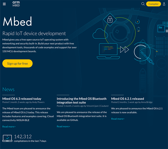
Figure 3: Mbed Development Site (Source: Mouser Electronics)
Project Application Source Code Files
For this project, the Mbed Online Compiler was used to create a set of project source code files that initialize the MAX32620FTHR and MAX30101WING, read the pulse oximeter sensor, and send the data to the Medium One IoT Platform through Wi-Fi. The project source code files are in a code repository on the Mbed site, where it can be pulled into your Mbed Online Compiler to modify it for your Wi-Fi and Medium One settings.
Software for the HUZZAH32 board is available in a second repository on GitHub that you will download and program onto the HUZZAH32 board using the Arduino IDE.
Medium One IoT Prototyping Platform
The Medium One IoT Platform (Figure 4) is designed to help early-stage developers prototype their IoT project or connect their existing hardware to the cloud. It offers an IoT Data Intelligence platform enabling customers to build IoT applications with less effort quickly. Programmable workflows allow you to promptly build processing logic without having to create your complex software stack. Configurable dashboards allow you to visualize application data and view real-time data in various formats. Medium One’s iOS and Android apps will enable you to build simple mobile app dashboards to communicate with your devices through the IoT platform.
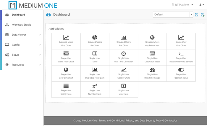
Figure 4: Medium One IoT Platform (Source: Mouser Electronics)
IoT devices can exchange data with Medium One through either a representational state transfer application programming interface (REST API) or Message Queuing Telemetry Transport (MQTT). More detailed information about the Medium One IoT Platform can be found here and on the Medium One site.
The Setup (Hardware)
While setting up the hardware, remember that electronic components are static-sensitive, so handle accordingly.
Personal Computer (PC)
Power up the personal computer and allow it to boot up.
Wi-Fi Access Point
Make sure your Wi-Fi access point runs with an active connection to the internet and a Dynamic Host Configuration Protocol (DHCP) server that assigns IP addresses. You’ll need to know the access point Service Set IDentifier (SSID) and security credentials to be used later when configuring the Wi-Fi connection.
MAX32620FTHR Feather Board
Unbox the MAX32620FTHR and lay out the components. Two boards are included in the kit: The MAX32620FTHR and a separate MAX32625PICO board used to program the MAX32620FTHR through its Serial Wire Debug (SWD port.
Solder the 485-2886 Adafruit Feather 12- and 16-pin female headers to the MAX32620FTHR board so that the sockets face up. Later, we will be plugging in two more boards on top in a stacked arrangement.
Follow the MAX32620FTHR Getting Started documentation to get the MAX32620FTHR and MAX32625PICO connected to your PC and running an initial Blinky program that blinks the onboard LED. It will walk you through the following steps:
- Connecting the MAX32625PICO to the MAX32620FTHR SWD port using the 10-pin cable
- Connecting the MAX32625PICO and MAX32620FTHR to your PC using USB cables
- Opening the MAX32620FTHR platform page in a web browser and creating a mbed account if you don't already have one
- Loading a Blinky program onto the MAX32620FTHR that blinks the onboard LED
The MAX32620FTHR is programmed by dragging and dropping a compiled binary file onto the USB drive provided by the MAX32625PICO. After a file is dropped onto this USB drive, it will be automatically programmed onto the MAX32620FTHR. After the programming has completed, press the RESET button on the MAX32620FTHR to get the program running.
After a program is loaded onto the MAX32620FTHR, the MAX32625PICO can be disconnected. However, we need to reprogram it in later steps, so keep it connected for now.
MAX30101WING Pulse Oximeter FeatherWing Module
Unbox the board and verify the headers are already installed. Do not connect the board to anything yet – first, we will need to set up the Adafruit HUZZAH32 and get its software installed.
Adafruit HUZZAH32
Unbox the HUZZAH32 and verify the stacking headers are already installed. Connect the board to your PC using a USB cable. Software setup will be covered in the next section.
The Setup (Software)
Set Up the Medium One Bridge Running on HUZZAH32
Web browse to here and follow the instructions for downloading the repository, installing the Arduino IDE and supporting libraries, and opening the application program in the Arduino IDE.
For the board selection, set BOARD_SELECT_HUZZAH32_SWAPPED to 1 and set the rest of the board select constants to 0. BOARD_SELECT_HUZZAH32_SWAPPED = 1 causes the HUZZAH32 serial port TX and RX lines to be reversed. This allows us to connect the HUZZAH32 headers to the MAX32620FTHR headers directly and have the TX and RX properly cross-connected.
Using the Arduino IDE, compile the program and upload it to the HUZZAH32 board. After the HUZZAH32 board is programmed, you can disconnect it from your computer.
Finish the Hardware Setup
Once the HUZZAH32 is programmed, disconnect it from the PC and remove the USB cable, as well as removing the battery if connected. Carefully bend the RST pin on the HUZZAH32 outwards, as shown in Figure 5. This will electrically isolate the HUZZAH32 RST signal from the Reset circuit on the MAX32620FTHR when the two boards are connected. Be sure to do this step. Otherwise, the HUZZAH32 won't start up properly.
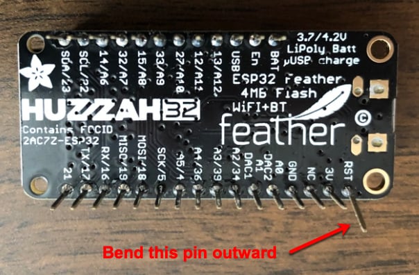
Figure 5: Bend HUZZAH32 RST Pin to Isolate Reset Signal (Source: Mouser Electronics)
Carefully plug the HUZZAH32 into the top side of the MAX32620FTHR, making sure that the bent RST pin on the HUZZAH32 does not connect to the MAX32620FTHR. Leave the 10-pin ribbon cable connected to the MAX32620FTHR.
Carefully plug the MAX30101WING into the top of the HUZZAH32 to form a stack of three boards resembling Figure 6. Note that Figure 6 shows extra pins extending from the bottom of the MAX32620FTHR, which you won't have.
Plug both of the USB cables from the MAX32620FTHR and MAX326250PICO to the PC. A DAPLINK USB drive should appear on the PC. This is the drag-and-drop programming interface.
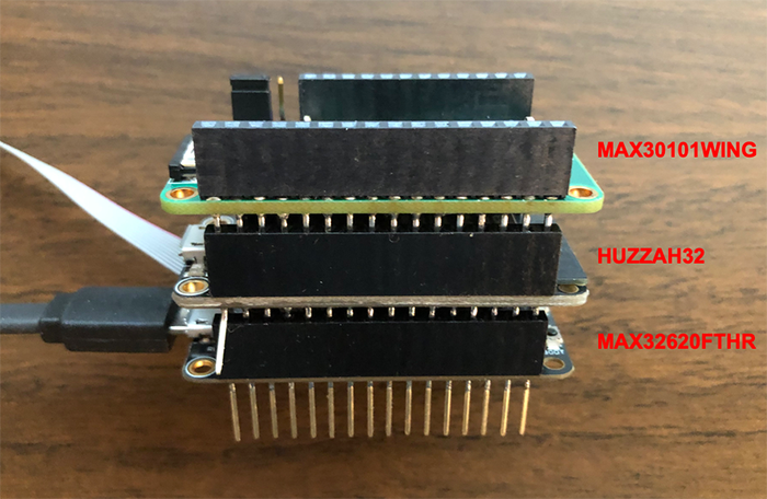
Figure 6: Board Assembly With Debug Cable Connected (Source: Mouser Electronics)
Set Up the Medium One IoT Cloud
Web browse to the Medium One IoT Platform and log in, after which you should see an initial dashboard resembling Figure 4. If you have trouble logging in, check your Medium One credentials to make sure you're using the latest URL provided with your sandbox subscription. Click Setup > Manage Users > Add New User. Set Username to mydevice, create a password of your choosing and enter it in both password fields, then click Save. In the Manage API Users list, you should see a new user account having Login ID = mydevice and an auto-generated user MQTT ID like Figure 7.
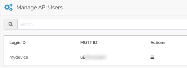
Figure 7: Newly Created User ID with Auto-Generated MQTT ID (Source: Mouser Electronics)
Click Setup > MQTT, and you should see a Project MQTT ID and a set of port numbers like Figure 8.
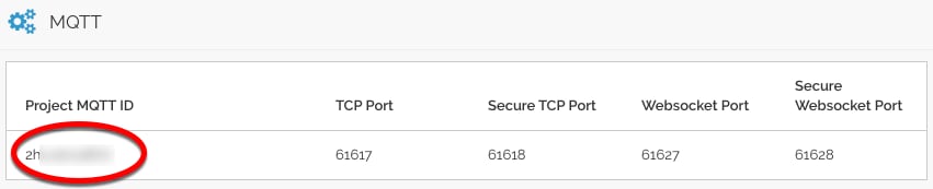
Figure 8: Project MQTT ID (Source: Mouser Electronics)
Medium One uses MQTT usernames and passwords for authentication. The MQTT username is created by combining the Project MQTT ID, a forward slash, and the user MQTT ID. For example, if the Project MQTT ID is “ZHxxxxxxx0Y” and the user MQTT ID is “sTxxxxxxx8w” the corresponding MQTT username would be “ZHxxxxxxx0Y/sTxxxxxxx8w”.
Next, we’ll create the MQTT password. Navigate to Setup > Manage API Keys > Add New API Key. Set the description to mydevice, make sure Enabled is check-marked, and click Save. The result should look like Figure 9.
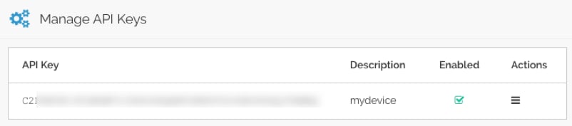
Figure 9: Newly Created API Key (Source: Mouser Electronics)
The MQTT password is created by combining the API Key, a forward slash, and the mydevice user password. For example, if the API Key is “PZxxxxxxxxxxxxxxxxxxxxxxxxxxxxxxxxxxxxxxxxxxxMBQ” and the mydevice user password is “AaaaBbbb3” the corresponding MQTT password would be “PZxxxxxxxxxxxxxxxxxxxxxxxxxxxxxxxxxxxxxxxxxxxMBQ/AaaaBbbb3”.
The MQTT topic has the following format: “0/Project MQTT ID/User MQTT ID/Device ID”.
The Device ID field can be anything, and we’ll use "mydevice" as the Device ID. For example, if the Project MQTT ID is “ZHxxxxxxx0Y” and the user MQTT ID is “sTxxxxxxx8w” the corresponding MQTT topic would be “0/ZHxxxxxxx0Y/sTxxxxxxx8w/mydevice".
The MQTT username, MQTT password, and MQTT topic strings will be added to the next step’s project source code.
Set Up the Main Application Program
Web browse to the Mbed site and click the Compiler button in the top right. Login using your existing Mbed account or create a new account. After logging in, you should see an initial workspace resembling Figure 10.
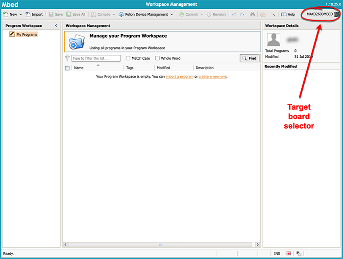
Figure 10: Initial Mbed Online Compiler Workspace (Source: Mouser Electronics)
In the upper right corner, click the target board selector (circled in red in Figure 10), click Add Board, and then search for MAX32620FTHR. Click on the MAX32620FTHR item in the search results and then click Add to your Mbed Compiler. Navigate back to the compiler, click the target board selector (upper right) again, and then select MAX32620FTHR from the registered platforms list. Click Select Platform to activate the selection. Afterward, the target board selector in the upper-right corner should say MAX32620FTHR.
Navigate here and click Import into Compiler. In the dialog that appears, select Import As Program, select the default Import Name of MAX30101WING_HR_SPO2, and leave Update libraries unchecked. Afterward, the Program Workspace area should show MAX30101WING_HR_SPO2 under My Programs.
Edit file main.cpp and set these constants to your Wi-Fi SSID and password:
- WIFI_SSID
- WIFI_PASSWORD
Set these constants to your own Medium One MQTT parameter strings as described earlier:
- MQTT_USERNAME
- MQTT_PASSWORD
- MQTT_PUB_TOPIC
Save the modified file and build the project by selecting Compile > Build Only. Verify the code compiles without errors. If you see compilation errors, check the changes you made to main.cpp. Some of the Mbed libraries can generate warning messages during the compilation.
Run the Application
In the Mbed Online Compiler, click the Compile button. At the end of compilation, a binary file should get downloaded to your PC. Drag and drop the downloaded file onto the DAPLINK USB drive to program it onto the MAX32620FTHR. Afterward, press the RESET button on the MAX32620FTHR to start the program. You might need to use a toothpick or pen to reach the RESET button in the board stack.
You can connect a serial terminal program such as Tera Term to the USB serial port on the MAX32625PICO if necessary to monitor debug messages from the MAX32620FTHR while it's running. Set the serial parameters to 115200,N,8.1. The MAX32625PICO connects to a UART on the MAX32620FTHR through the debug cable.
How the Application Program Works
This program was created using the Mbed Online Compiler and is derived from the Maxim MAX30101WING_HR_SPO2 example program. The high-level program flow includes:
- Initialize hardware
- Maintain processing state machine
- Initialize serial connection to ESP32 bridge
- Connect to Wi-Fi via bridge
- Connect to Medium One MQTT broker via bridge
- Periodically read sensor
- Generate JSON-formatted MQTT payload messages and send to Medium One MQTT broker via bridge
MQTT Payload Format
MQTT messages are formatted as JSON strings according to the Medium One MQTT payload specification. Here’s an example message:
{"event_data":{"iteration":25,"timestamp":31684,"valid":0,"hrbpm":0,"spo2":0}}
Fields:
- iteration = counter that increments by 1 each event_data message
- timestamp = milliseconds since the board started
- valid = 1 if MAX30101 sensor has valid reading, 0 if not
- hrbpm = measured heart rate in beats per minute, or 0 if no reading available
- spo2 = measured blood oxygen level in percent, or 0 if no reading available
When no finger is resting on the MAX30101WING sensor, the valid, hrbpm, and spo2 readings will be 0. You will see these values on the debug serial port, and they are also visible in Medium One (described below).
Place a finger on the MAX30101WING pulse oximeter sensor. After a short while, the valid indicator should change to 1 and spo2, and hrbpm should have non-zero values. You might have to move your finger around and try different amounts of pressure to get the readings to start. Take your finger off the sensor to return the readings to 0.
View Data in the Medium One Dashboard
In the Medium One dashboard, navigate to Data Viewer > Data Streams and click raw Events. You should see raw messages (Figure 11) being received from the MAX32620FTHR. Click the “+” sign to view message details.
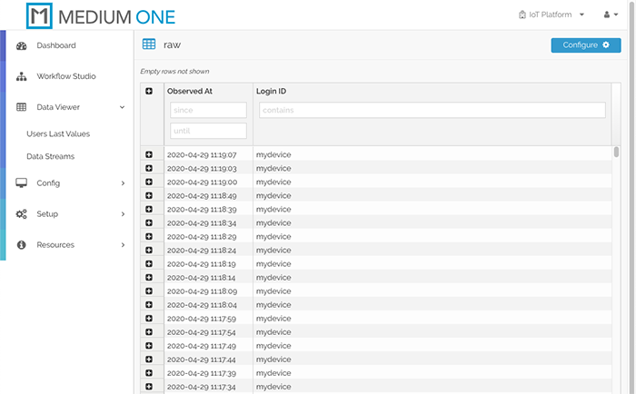
Figure 11: Raw Message Display (Source: Mouser Electronics)
Click Dashboard on the top left, then click Add Widget > Single User Real Time Events Stream to add an event stream widget to the dashboard.
In the Select user dropdown, select mydevice. You should now see messages appearing in the Real Time Events Stream widget (Figure 12). Click the save icon in the upper-right corner to save your modified dashboard.
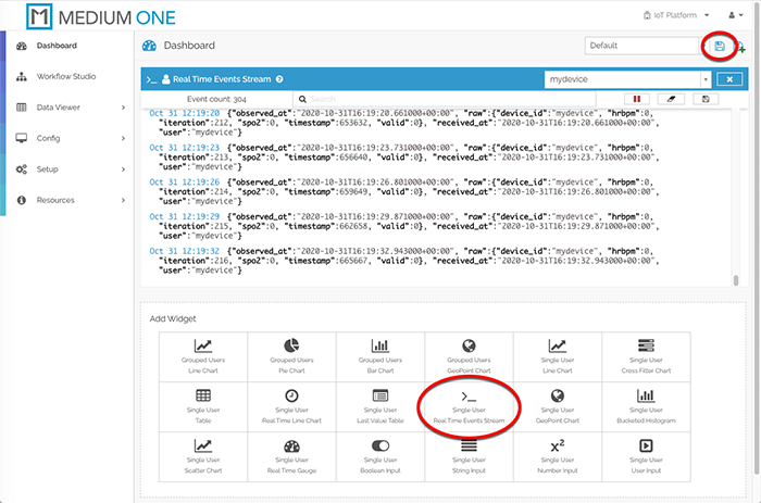
Figure 12: Real Time Events Stream Widget Display (Source: Mouser Electronics)
Add More Widgets
To display more widgets, we need to enable specific data fields contained in the message payload. Navigate to Config > Data Streams and click on raw Events. The Schema Map should be pre-populated with fields detected in the incoming messages. However, they are currently disabled. Check-mark the Active box on raw.hrbpm, raw.iteration, raw.spo2, raw.timestamp and raw.valid, then click Save Data Stream. These fields are now available for use in other dashboard widgets.
Back on the dashboard, click the Single User Last Value Table widget and select the widget’s mydevice user. Click the widget’s Tag Config icon to the right of the mydevice user selection and check-mark raw:hrbpm, raw:iteration, raw:spo2, raw:timestamp, and raw:valid, then click Save. The Last Value Table should now populate with the most recent received values for each field (Figure 13). Click the save icon toward the upper-right corner to save the updated dashboard.
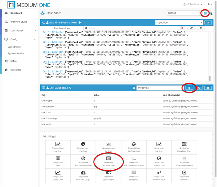
Figure 13: Last Value Table Widget Display (Source: Mouser Electronics)
Now let’s add dashboard widgets for the valid flag, iteration counter, hrbpm, and spo2 values. Click Single User Real Time Gauge and select the mydevice user. Click the widget’s Tag Config icon and check-mark the raw:hrbpm, raw:iteration, raw:spo2 and raw:valid rows, then click Save. The updated dashboard should look like Figure 14. Click the dashboard save icon to save the updated dashboard. Try placing your finger on the MAX30101WING sensor to see the spo2 value change.
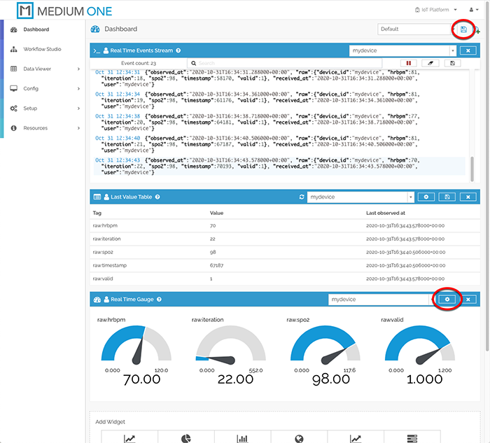
Figure 14: Real Time Gauge Widgets added to dashboard (Source: Mouser Electronics)
At this point, your MAX32620FTHR board is running continuously, periodically reading the sensor and transmitting data measurements to the Medium One cloud. Figure 15 shows the completed project running with the debug cable disconnected. Place your finger on the illuminated red/green sensor to take a measurement. Remember to power off the MAX32620FTHR board when you’re done. Otherwise, the board will continue to send messages to Medium One and consume daily message allotments.
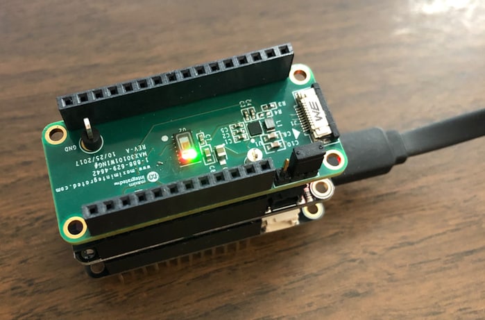
Figure 15: Completed Project (Source: Mouser Electronics)
Troubleshooting Tips
- Make sure the board setup is correct, and the HUZZAH32 RST pin is not connected to the MAX32620FTHR.
- Make sure HUZZA32 is set up and programmed according to the instructions.
- Make sure the Wi-Fi and Medium One settings are correct, including the MQTT port number.
- View information messages on the MAX32620FTHR debug serial port.
- View information messages on the HUZZA32 USB serial port.
- Move your finger around on the sensor and try different pressures to get a valid reading.
Conclusion and Where to Go Next
This project created an internet-connected pulse oximeter sensor that sends real-time sensor data to the Medium One IoT Platform. It can be modified and extended in several ways, and here are a few examples:
- Dive deeper into the application code and board hardware by reading the Maxim documentation and studying the source code.
- Add more widgets to the Medium One dashboard, such as a real-time line chart of sensor readings.
- Learn about the Medium One Workflow Studio, which lets you create data-processing workflows to transform your sensor data.
- Experiment with the Medium One mobile apps.
- Modify the sensor data publishing interval by modifying the application source code.