Not By MOSFETs and Processors Alone: Passive Components Also Critical to Advanced Motor Control
The internal-combustion car historically had only one high-current electric motor: the starter. This 12-V/100-A (typical) unit does not need sophisticated control, as it is just an on/off, "give it the full 12 V DC and let it rip" motor. The few other motors were small and easily controlled, such as for the windshield wipers.
Jump to the present: Today's cars have dozens of small and medium-size motors for power windows, seat adjustment, outside mirrors, and vent controls, for example. The number of wiring loops in a car for all these functions became so high that car motors are now networked, as individual wire runs were taking up too much space, adding considerable weight, hard to trace and debug, and exploding the BOM cost.
Featured Products
Featured Suppliers
Related Resources
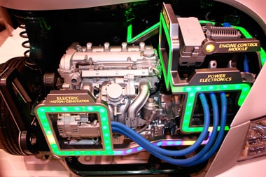
Further, motor demands have increased dramatically with electric vehicle (EV) and hybrid electric vehicle (HEV) automotive designs. The vehicle electric systems now must route power at many hundreds of amps and several hundred volts or more to the wheel motors (the Toyota Prius motors operate at 200 V), and these motors must be carefully controlled to meet performance requirements.
Motor control, however, is more than just the obvious MOSFETs that switch power to these motors, and the processors that execute the embedded motor control algorithms and energize/de-energize the MOSFETs. While active components are obviously critical, they are only a small part of the total picture. The need to power and control these numerous, widely disbursed motors, ranging from moderate to higher-power units, are placing difficult demands on two groups of passive components:
- Sense resistors for the motion-control loop, which allow the motor controller to know precisely what the motor is doing and how well it is doing it. The challenge of doing so increases with higher currents and voltages.
- Connectors that can handle the voltage and power, and are compact, cost-efficient, safe in use, easily disconnected/reconnected for factory test and field repair, and reliable despite the harsh automotive environment.
Sensing the Current Flow
When it is necessary to know what the motor is doing, to be able to compare with the commanded motor action (position, speed), some sort of feedback is needed. This can be obtained by using a shaft encoder (Hall-effect, optical, magnetic) or sensing current flow through the motor windings. Generally, designers like to start with the current-sensing approach alone, because it is less expensive and physically easier to implement than a shaft encoder.
For current sensing, the topology is simple at first appearance: a resistor is placed in series with each motor winding and the voltage across it is sensed and monitored by the motor controller (Fig. 2). This resistor is often called a "shunt," but this is a misnomer, as it is in series with the winding and not shunting the current flow. (Note that there are other ways to sense, including noncontact approaches such as a Hall-effect device or sensing coil on the motor lead, but these are beyond the scope of this article.)
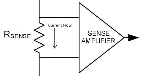
Figure 2: The easiest way to measure motor current, in concept, is by simply measuring the voltage drop across a suitably sized sense resistor, which is in series with the motor (sometimes called a "shunt" resistor).
The resistor value is usually chosen so that maximum voltage developed across it will be about 1 V, depending on the current value and the voltage rail of the sensing circuit, which is often not the same as the voltage supplied to the motor. In general, sensing resistor values are well below 1 Ω, to minimize drop, reduce resistor dissipation, minimize wasted power, and not affect loop stability. Since the resistor is in the motor-control feedback loop but separate from the inherent resistance of the motor windings, it can affect loop dynamics and stability. Further, basic math shows that for larger motor currents, the resistor value must be decreased to as small as possible to minimize the voltage drop across the resistor, especially critical in designs with low supply voltages.
Although selecting a sense resistor seems like a simple decision based on V = I x R, it is not. There are multiple conflicting factors to consider:
- Resistor value: Lower-value resistors minimize losses and impact on loop performance. However, these lower resistors produce lower voltages, which may be harder to accurately sense, especially in noisy environments. Therefore, the desire for larger voltages across the sense resistor is in conflict with the preference for a lower-value resistor. A high-current situation will actually use a resistor in the sub-milliohm range.
- Resistor power rating: Even though the resistor is usually a sub-ohm value, it can have significant current through it, and must be selected with an appropriate dissipation rating. A 0.1-Ω resistor carrying 10 A will dissipate 10 W; that's a lot of concentrated heat.
- Temperature coefficient of resistance: Like all components, resistors have a temperature coefficient (tempco). While this may seem like a negligible issue here, it is not. Often, the motor area gets fairly warm, so the resistor's value will change significantly. Given the level of measurement precision needed and the temperature swing, this may put accuracy of the reading outside of what is acceptable.
- Associated circuit traces: The resistance of the PC board traces and solder joints to and from the sense resistor may seem small, but they actually can be significant compared to the resistor itself. Therefore, exactly where the sensor-resistor picks off traces to make connections, and the tempco of these elements of the circuit path, will affect the initial and long-term readings.
- Packaging: At lowest currents, standard surface-mount (SMT) resistors are used; for moderate levels, the resistors are SMT or axial-leaded devices; and for the highest power levels, the resistors may be packaged for screw or stud mounting. Some high-current, low-ohm sense resistors look like small, all-metal tabs or miniature bus bars. An example of a medium-power sense resistor is the Vishay/Dale WSBM8518L1000JK, a 0.0001-Ω metal strip battery-shunt resistor rated for 36 W (Fig. 3). This is a surface-mount device with large tabs, measuring 12.7 (H) x 43.2 (L) x 38.1 mm (W), with ±5% tolerance and a temperature coefficient of ±225 ppm/°C. It also includes a connector to simplify the voltage-sensing connection.
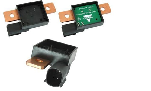
Figure 3: Sense resistors are available in many physical forms and resistance values and, in general, are in the milliohm range to minimize series loss of supply voltage to the load, and dissipation due to power loss. This Vishay/Dale WSBM8518L1000JK 0.0001-Ω unit with integral voltage pick-off connector and can handle up to 36 W. (Source: Mouser/Vishay Dale)
While this is a relatively large temperature coefficient, it is acceptable in many applications. Resistors are available with lower temperature coefficients, such as the Vishay/Dale WSMS3124L1000JK (Fig. 4), a 0.0001-Ω 3-W unit with drift of ±75 ppm/°C; this metal-strip unit measures 3.3 (H) × 55 (L) × 15 mm (W).
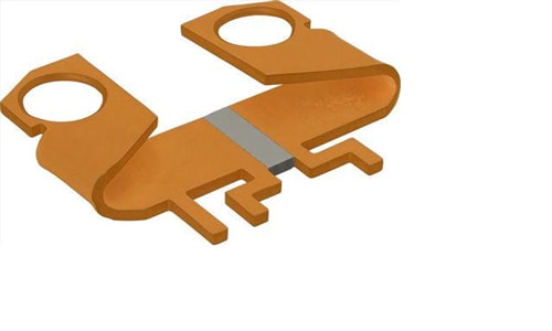
Figure 4: Some sense resistors are precision-value metal tabs, such as the 0.0001-Ω 3-W WSMS3124L1000JK from Vishay/Dale. (Source: Vishay Dale)
Sensing current: Go high (side) or go low?
Even after all the above items have been resolved, there is still one large issue that the designer must address: whether to use high-side or low-side sensing of the series resistor. Neither one is inherently better, but each brings tradeoffs and has implications that must be considered in the context of the application.
In low-side sensing (Fig. 5a), the resistor is connected between the motor as "load" and the system common (often called "ground" even if it not really connected to a true Earth ground). As a result, the circuit that senses the voltage across the resistor can also be grounded. This simplifies the design and implementation of the sensing-circuit design, as well as interfacing it with the next stage of the feedback subsystem.
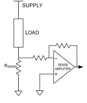
Figure 5A: Low-side sensing places the resistor between the load and ground.
However, low-side sensing also means that the load itself is no longer grounded. This has serious implications for the physical connections of the load and user safety. Since the load's low side is above ground, no part of it can be connected to ground such as the car chassis or grounded enclosure; instead, it must be electrically isolated from ground. Further, since the low side of the load is no longer at ground potential, the drive circuit to the load and any voltage measurements made across the load (which is not the same as readings across the sensing resistor) must be made differentially or via a circuit isolated from ground.
The alternative is high-side sensing, where the sense resistor is between the power rail and the load, while the load itself remains grounded (Fig. 5b). This is much better from a load installation and overall safety perspective, but it means that the circuit for the sensing resistor cannot have a direct ground connection. Instead, it must done using a differential amplifier based on an instrumentation amplifier, or even galvanically isolated using isolation components. This is somewhat more complex and costly than a circuit that can be connected to ground. Further, the sensing circuit must be designed to work at the common-mode voltage of the system, and have high CMRR (common mode rejection ratio) to sense and extract fairly small voltage variations (millivolt range) in the presence of tens or even hundreds of volts.
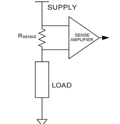
Figure 5B: High-side sensing puts the resistor between the supply rail and the load. Both low-side and high-side sensing offer well-defined electrical, safety, and installation attributes.
While every application is different, most designers now choose the high-side approach. This is because it solves or avoids some challenging electrical, safety, and installation issues that are inevitable with ungrounded loads. Also, the circuitry to do high-side current sensing via small voltages (using differential amplifiers and isolation components) is modest in cost and small in size.
Regardless of whether high-side or low-side sensing is used, the resistor decision must balance many factors: the correct ohm value (of course), sufficient power rating, and physical packaging matched to the application.
Connectors can't be overlooked, either
Designers who are selecting connectors for motors in cars must remember two basic facts. These apply whether the vehicle is an internal combustion design (gas, diesel, even hydrogen-powered), or an HEV/EV with higher currents and voltages:
- Higher currents require larger contacts to carry the current, minimize IR losses, and reduce I2R self-heating; these contacts, in turn, require more substantial connector bodies.
- Higher voltages, even at low currents, require greater separation between contacts to meet creepage and clearance safety requirements, so there will no sparking or flashover between contacts. (Note: creepage is the distance an arc may travel as measured over a surface, such as between two traces on a printed-wiring board or across the surface of a connector or IC. Clearance is the shortest distance an arc may travel through air, such as from pin-to-pin of a connector or IC.)
The factors of required contact size and mandated spacing define the available connector options. In addition, some multi-pin connectors are designed to mix various current/voltage specifications, to save space and cost. Some motor connectors are for power only, while the control-network bus uses another path and respective connector; other implementations combine both power and control functions into a single connector.
For example, the Molex ML-XT™ Sealed Connection System (Fig. 6) which offers superior reliability for critical automotive vehicle-wiring applications. This rugged sealed connection system is available in 2, 4, 6 and 18-contact positions with crimp termination. They are designed for use within the wiring architecture of a vehicle and carry an IP68 rating.
ML-XT connectors feature a one-piece housing and seal design, permanently bonded by two-shot LSR (liquid silicone rubber) molding technology and utilizes Molex proven XRC™ terminals with current ratings up to 13.0A and 500VDC. They also utilize Wedgelock / TPA (Terminal Position Assurance) to lock terminals in position for secure electrical contact.
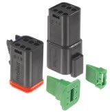
Figure 6: Molex ML-XT Sealed Connection System carries terminal current rating up to 13A and are IP68 rated. (Source: Mouser/Molex)
Regardless of the option selected, reputable vendors specify the maximum current and voltage ratings (at nominal and maximum temperature), and call out which regulatory standards the connector will meet under specific design-in circumstances. There are also temperature and flammability ratings that apply to specific motor applications and in-vehicle locations.
Today's cars have dozens of motors and hundreds of connectors, each chosen on the unique needs of the application as well as cost, availability, and sourcing options. Stepping back, it results in a complex wiring-diagram schematic, harness assembly drawings, installation instructions, and bill of materials.
Additional resources to read:
- "Optimize High-Current Sensing Accuracy by Improving Pad Layout of Low-Value Shunt Resistors" from Analog Devices
- "Choosing the right sense resistor layout" from Texas Instruments