Closed-loop motor control: An Introduction to Rotary Resolvers and Encoders
Introduction
Is your motor spinning at the intended rate? Closed-loop motor control systems continue to answer this question, as there tends to be a closed-loop system implemented wherever a motor spins. Whether the end system is an automobile (assisted parallel parking with computer controlled steering), a satellite (positions satellite to lock on to a specific signal), or factory floor machinery (a pick and- place machine), the position feedback sensor is an intrinsic element in the total motor-control system. There are many types of motor control, but this article discusses two that implement an analog signal chain around the position sensor: the resolver and the encoder.
Resolver
Before discussing the signal-chain solution for a resolver, consider its basic operation in Figure 1. The resolver (in this case, a transmitter unit), is made up of three distinct coil windings: the reference, the sine (SIN), and the cosine (COS). The reference winding is the primary winding that, through a transformer known as the rotary transformer, is excited by an AC voltage applied to the primary side of the transformer. Since the rotary transformer then passes the voltage off to the secondary side of the transformer, no brushes or rings are needed. This increases the overall reliability and robustness of the resolver.

The reference winding is mounted on the motor shaft. As the motor spins, the voltage output from the SIN and COS windings change according to the shaft position. The SIN and COS windings are mounted 90® from each other in relation to the shaft. As the reference winding spins, the angle of difference between the reference and SIN/COS windings change, represented as the theta rotation angle or θ in Figure 1. The voltages induced upon the SIN and COS windings are equivalent to the reference voltage multiplied by the SIN winding and COS winding of angle theta.
The induced output voltage waveforms are shown in Figure 2. They show the normalized voltage-output signals from the SIN and COS windings, divided by the reference voltage. Traditional reference voltages are anywhere in the 1- to 26-V range, and the output frequency range is 800 Hz to 5 kHz.1
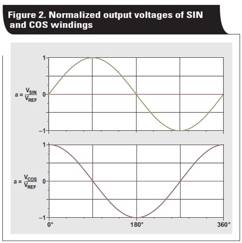
It is now possible to determine the requirements for the appropriate signal-chain devices. The signal chain needs to be bipolar because to the signal swings below ground (Figure 2). It must simultaneously sample two channels, convert up to 5-kHz signals, and supply AC voltage to the resolver for the reference winding. The optimum solution is to implement two delta-sigma modulators, one for each channel. The delta-sigma modulators sample at very high frequencies (in the 10- to 20-MHz range), so the deltasigma modulated outputs are averaged out and filtered to achieve an acceptable resolution.

For the reference voltage or AC-excitation source, a pulse-width modulation (PWM) signal applied directly to the resolver is preferred. TI has a recommended solution for this kind of implementation. A data converter such as the ADS1205 or ADS1209 is preferred for the delta-sigma modulator because both are designed for direct interface to the resolver's SIN and COS windings. The data converter also interfaces to a four-channel sinc filter/integrator with a PWM signal generator output for the reference winding, for example the AMC1210. Finally, a digital signal processor (DSP) or real-time controller is needed to handle all the various signals in addition to the motor control system. One such option is the C28x-based C2000™ Piccolo™ F2806x microcontroller from TI. Figure 3 illustrates a typical signal-chain solution.
Conclusively, a resolver is a very robust position sensor for a control system that offers high accuracy possibilities and long operating life. A disadvantage of the resolver is its maximum rotational speed. Because resolver signal frequencies tend to be less than 5 kHz, motor speeds need to be less than 5,000 revolutions per minute.
Encoder
As with the resolver scenario, before going into the signalchain implementation, is important to understand the physical and signal-output characteristics of encoders. Typically there are two types of encoders: linear and rotary. Linear encoders are used for items moving only in a single dimension or direction, and convert the linear position into an electronic signal. These often are used in conjunction with actuators. Rotary encoders are used for items moving around an axis, and convert the rotary positions or angles into electronic signals. Since rotary encoders are used with motors (as motors rotate along an axis) linear encoders are not covered in this article.
To understand the principle behind a rotary encoder, first consider a basic optical rotary encoder. An optical encoder has a disk with specific patterns mounted to the motor shaft. The patterns on the disk either blocks light or allows it to pass through . Thus, a light-emitting transmitter is used along with a photocel receiver. The receiver signal output can be correlated to the motor's rotary position.
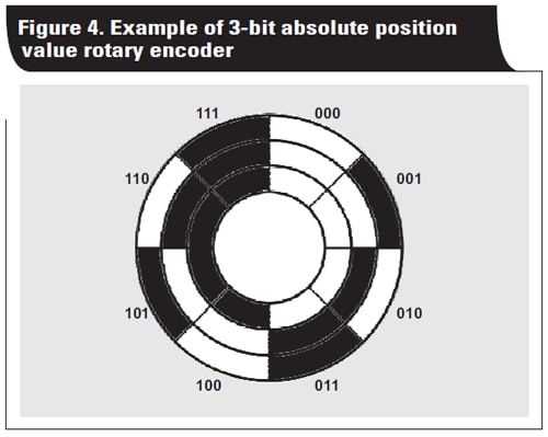
There are three common types of rotary encoders: absolute position value, incremental TTL signal, and incremental sinusoidal signal. For absolute position value rotary encoders, the pattern on the disk is broken up into a very specific pattern based on its location. For example, if the absolute position encoder has a 3-bit digital output, it would have eight different patterns, evenly spaced (Figure 4). Since this is on a disk and is evenly spaced out, the spacing between each pattern is 360°/8 = 45°. Now the position of the rotary motor is known to be within 45° for a 3-bit absolute position value rotary encoder.
The output of the absolute position value rotary encoder is already optimized for digital interfaces, so an analog signal chain is not required.
For the incremental TTL rotary encoder, the pattern on the disk outputs a digital high or low, which is a TTL signal. As shown in Figure 5, the TTL-output disk pattern is relatively simple compared to the absolute position value rotary encoder, because it needs to represent only one digital high or digital low. In addition to the TTL signal there also is a reference mark which is essential in determining the motor's current rotary position. The reference mark can be thought of as angle 0°. Thus, simply counting the digital pulses can determine the exact rotary position of the motor.
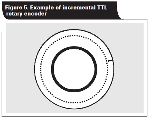
Figure 5 illustrates multiple periods in one revolution of the motor shaft. Encoder manufacturers offer incremental TTL rotary encoders (and incremental sinusoidal rotary encoders) with 50 to 5,000 periods per revolution. As with absolute position value rotary encoders, the output is already in a digital format, so no analog signal chain is required.
For the incremental sinusoidal rotary encoder, the output and disk pattern is quite similar to the TTL-signal encoder. Instead of a digital output, the output is what the name implies: a sine wave output. Actually, it has both sine and cosine outputs along with the reference mark signal as shown in Figure 6. These outputs are all analog, so an analog signal-chain solution is required.

Similar to the incremental TTL output, there are multiple signal periods in one revolution. For example, if the encoder with 4,096 periods in one revolution is selected and attached to a motor spinning at 6,000 revolutions per minute, the resulting sine and cosine signal frequencies can be calculated.
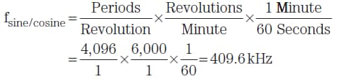
A signal-chain solution needs to have a bandwidth of at least 410 kHz for this example. Since this is a closed-loop control system, latency must be kept to a minimum or completely eliminated. Traditionally, the encoder output is 1 VP-P, and the sine and cosine output signals are differential.
The typical requirements for the analog signal-chain solution are:
- Two simultaneously-sampling analog-to-digital converters (ADCs): One for sine and one for cosine outputs.
- No system latency: More than 400 kHz of bandwidth are needed, thus an ADC must handle 800 kSPS per channel minimum.
- 1-VP-P differential input with a full-scale range of around 1 V to optimize the ADC's full-scale range, or amplification of the input signal to the ADC's full-scale range.
- A comparator for the reference-mark signal.
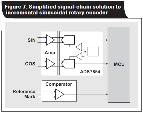
The optimum solution from TI is the ADS7854 family of successive-approximation register (SAR) ADCs (Figure 7). With two simultaneously-sampling channels, an internal reference and 1-MSPS per channel output data rate, this SAR-ADC meets the specified requirements. It can be used with a comparator and a fully-differential amplifier to drive the ADC.
Because the ADS7854 is a 14-bit ADC, and if the sinusoidal incremental rotary encoder has 4,096 periods in one revolution, the total number of measuring steps can be calculated.
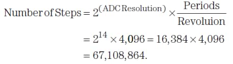
This gives the designer 26-bits of resolution when implementing this approach, or accuracy of the rotary position to within 5.36 × 10⁻⁶ degrees.
Conclusion
There are two common implementations of rotation/position sensors in a motor-control feedback path: a resolver and an encoder. The feedback path and output signal characteristics of several control systems were evaluated from the analog signal-chain perspective for either a resolver or encoder to ensure signal integrity and optimum performance.
References
- Advanced Micro Controls, Inc. (AMCI), "What is a Resolver?" Available: www.amci.com/tutorials/tutorialswhat- is-resolver.asp
- Texas Instruments. "Dual Channel Data Acquisition System for Optical Encoders, 12 Bit, 1MSPS," TI Prevision Verified Design. (06 June 2013). Available: www.ti.com/2q14-tipd117
- Delta Computer Systems, "Resolver Fundamentals" Available: www.deltamotion.com/support/
- HEIDENHAIN Brochure, "Rotary Encoders," November 2013, p. 13. Available: www.heidenhain.com/
Article written by Dwight Byrd, Precision Data Converters, Texas Instruments