The Wide Bandgap Road to Automotive Power Electronics
The Wide Bandgap Road to Automotive Power Electronics

Image Source: WStudio/Shutterstock.com
By Bonnie Baker for Mouser Electronics
Published June 29, 2021
The market for automobile power electronics continues to grow in electric vehicles (EV), hybrid, and gasoline autos where silicon (Si) and wide bandgap semiconductor devices, such as gallium nitride (GaN) and silicon carbide (SiC) devices, are attracting significant interest.
The voltage requirements for the hybrid-electric-vehicle (HEV) power systems range from 12V to 800V with hundreds of ampere currents.
The wide-bandgap semiconductor devices are excellent alternatives, providing high electric breakdown fields, thermal conductivity, and saturated electron drift velocity. But their cost overshadows their performance when it comes to automotive power electronics systems in consumer vehicles.
Wide bandgap SiC or GaN devices, compared to silicon (Si) and gallium arsenide (GaAs) processes, bring higher efficiency, switching frequency, operating temperature, and operating voltage to solve this power conversion problem. But, again, they are often too expensive to use in automotive applications.
The range of electronic vehicle options spans between the full hybrid electric vehicle (FHEV), plug-in hybrid electric vehicle (PHEV), and mild hybrid electric vehicle (MHEV).
The average car has 600 MOSFETs, high-end cars have 100 MOSFETs, and the 48V Mild-hybrid car has 400 MOSFETs. The silicon MOSFET devices address these high voltage and cost issues. After solving over-voltage imbalance issues, the lower voltage power semiconductor devices in a series-connected configuration create an effective power conversion systems solution, meeting cost and efficiency problems.
The following examines how to use standard silicon buck-converter MOSFET circuity in a 48V MHEV. This 48V battery system withstands high input-voltage load-dump transients while operating with low electromagnetic interference (EMI), low duty cycles, and high efficiency.
Parallel MOSFETs
Electric power steering, pumps, fans, and body applications drive applications using 48V MOSFETs vehicle systems (Figure 1).
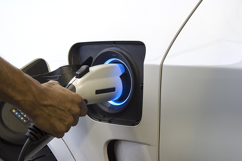
Figure 1: MHEVs provide better options for gasoline fuel emissions standards. (Source: Smile Fight/Shutterstock)
In these systems, MOSFETs experience a significant amount of mechanical stress during operation because a lot of expansion and contraction happening at any time. The materials in vehicles include copper, aluminum, and FR4. All these materials have different coefficients of thermal expansion.
The primary MOSFET devices must conduct high currents from the battery to the system. If the configuration of these MOSFETs is parallel, the system challenge keeps current and temperature imbalances under control (Figure 2).
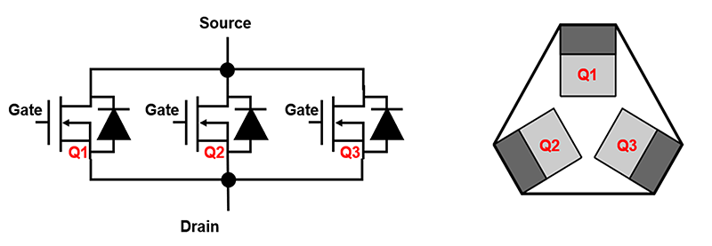
Figure 2: MHEV 48V system where three paralleled MOSFETs are in a symmetrical loop on the PCB face. (Image: Author)
Figure 2 shows three MOSFETs in a ring configuration. In this arrangement, the MOSFET sources connect to a star point. The symmetrical connections to the drain loop connect the electrical and thermal paths between the MOSFETs.
MOSFETs must have the ability to dissipate as much power as possible to optimize MOSFET performance and keep the junction temperature of the hottest MOSFET below the maximum safe temperature of 175°C.
To realize this goal, matching and minimizing the thermal resistance between each MOSFET's mounting base and the mounting bases of all the other MOSFETs is critical. The mounting of each MOSFET is symmetric and as close together on a thermally conductive surface.
A low thermal resistance path allows the easy flow of heat between MOSFETs. Heat flow can be analogous to electric current flow—so, the MOSFETs' thermal bonding points or drain tabs should be on a thermal ring main. The MOSFETs' mounting base temperatures track together closely when heat flows easily between all the MOSFETs in the group.
This arrangement promotes better die temperature matching, not equal current sharing.
Auxiliary 48V System
A braking action causes energy to flow from the combustion engine to the 48V battery, and engine torque to the Belt-Driven Starter Generator (BSG) which acts as a generator. A three-phase inverter via the silicon insulated-gate bipolar transistor (IGBT) or MOSFET intrinsic diodes rectifies the BSG electric waveforms to charge the 48V battery with direct current (Figure 3).
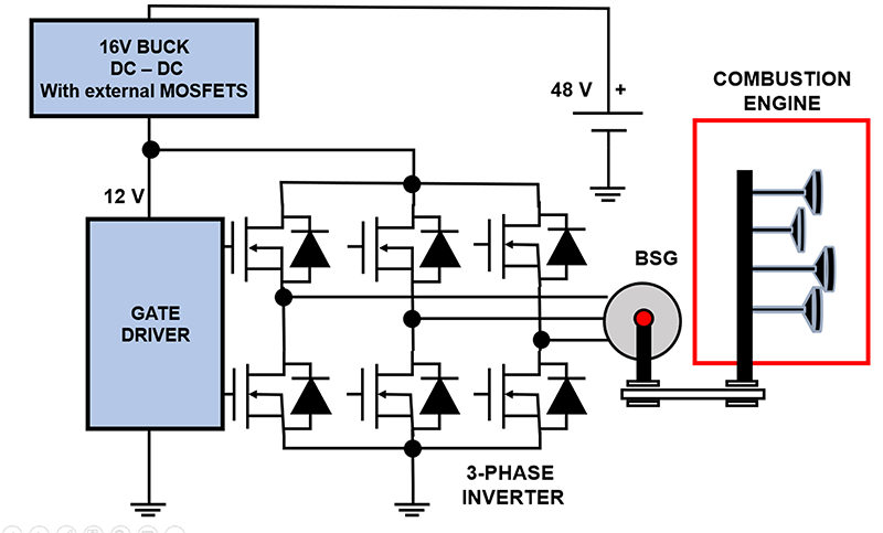
Figure 3: An auxiliary 48V system (Image: Author)
Energy flows to the BSG from the 48V battery during start-stop activities to act as a motor. During this time, the 48V battery provides power to the BSG and draws power by using three-phase silicon power transistor inverters. A DC-DC buck converter lowers the 48V to 16V, powering 3-phase inverter gate drivers. This provides the BSG with the proper motion sequence.
The BSG accomplishes three tasks by starting the engine during start-stop, improving acceleration performance by boosting the torque, and braking actions charge the battery. The 48V battery also powers pumps, fans, compressors, electric power steering racks, and aids start-stop systems. A 48V battery can deliver the same 12V battery power with a quarter of the current.
Using a 48V Battery
A lithium-ion MHEV battery specification can be 1kWh, 48V, 21Ah. The “VDA320: Electric and Electronic Components in Motor Vehicles 48V On-Board Power Supply” document recommends that the battery voltage operating range is between 36V and 52V. This specification allows limited operating modes between 20V and 60V and a dynamic overvoltage up to 70V. The 60V maximum operating voltage is the maximum permissible safe contact voltage for human operators.
DC-DC Buck Converter Robustness
The 48V buck converter in Figure 2 can be subject to voltage spikes as high as 70V and electrical stress up to 40ms. Operation above this limit can cause permanent device damage. Accordingly, the absolute maximum rating of the buck converter's input voltage needs a margin above 70V.
Auto Power Electronics Require Low EMI
EMI is a disturbance that originates in an external source. This coupled interference affects an electrical circuit by electromagnetic induction, electrostatic coupling, or conduction. Automotive power management electronics must have EMI protection.
In automotive environments, the 48V buck converter must meet the EMI's CISPR25 Class 5 specifications. Fixed-frequency converters usually attenuate spikes during both conducted and radiated testing. Adjustable DC-DC frequency allows engineers to filter specific frequencies when passing EMI tests. By distinction, constant on-time architectures exhibit those variable frequencies seldom have good EMI performance.
The 48V Front-End Buck Converter
Automobiles have numerous electronic control units (ECUs) with good EMI performance. The robust front-end 48V buck converter interface withstands the battery's static and dynamic voltage conditions. Additionally, this interface supports various 16V to 20V output voltage, motor-control gate drivers while providing MCU backup power if a 12V battery is disconnected.
The 48V buck converter versus the 12V buck tends to have higher switching loss (Equation 1).
PSW = ½ x C x V2 x f Eq. 1
Where C is the parasitic capacitances
V is the buck converter output
f is the operating frequency
By reducing the frequency of operation (f), the switching loss diminishes. Additionally, the adaptation of an advanced process with smaller minimum features lowers parasitic capacitances (C). The control technique leads to low-duty cycle operation. For example, a 16V output and a 48V input lead to Equation 2.
D = BUCK1/ BUCK2 Eq. 2
D = 16 / 48
D = 0.33
Where D is duty cycle
BUCK1 and BUCK2 rated output voltages
From this calculation, the high-side transistor of the buck converter conducts 33 percent of the time while the low-side transistor conducts 67 percent. This calculation can guide the sizing of the power transistors for optimum performance.
Conclusion
The silicon MOSFET devices address these high voltage and cost issues. After solving over-voltage imbalance issues, the lower voltage power semiconductor devices in a series-connected configuration create an effective power conversion systems solution, meeting cost and efficiency problems.
For these vehicles, lower voltage rating power semiconductor devices benefit by offering an efficient, low-cost power conversion solution. The inexpensive low voltage series silicon designs fit the bill in the automotive environment.