Home Automation with Microchip's IGaT
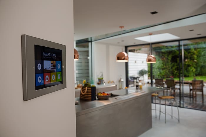
Image Source: KOTO/Stock.adobe.com
By Michael Parks, PE, for Mouser Electronics
Published April 14, 2022
Introduction
Time to market is a critical consideration in product development. First mover benefits can be substantial if the product is high quality and proves useful to customers. Rapid prototyping is a key enabler for projects that emphasize getting to market fast, and an essential rule of thumb of rapid prototyping is to avoid reinventing the wheel if possible. Microchip's Integrated Graphics and Touch (IGaT) Development Kit (Figure 1), powered by a single ARM Cortex M4 SAM E51 microcontroller, is an excellent solution for developing a product that requires a touchscreen.
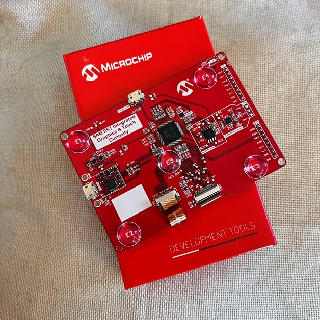
Figure 1: Microchip's IGaT Curiosity development board makes prototyping touch display applications as simple as drag-and-drop. (Source: GSG)
Home automation is one such application where a touch-based interface can be handy. Today, most people are comfortable with touch interfaces making them nearly universally accepted as a user interface. Moreover, they can be made dynamic to change based on context (i.e., having a day and night color palette). This project will show how to use Microchip IGaT hardware and their MPLAB X IDE and Harmony3 development tools to quickly create a graphical user interface. In addition, we will show how to get the dev board to interact with a relay and passive infrared sensor to create a proof-of-concept lighting control system.
Lastly, we will examine how machine learning technology can give our home automation device a bit of intelligence with a smart mode that can turn lights on and off without direct human interaction.
Project Materials and Resources
The project is centered around Microchip's IGaT Curiosity development board. Some of the key features of this particular board are the following:
Bill of Material (BOM)
You can click this Mouser project share link to access the BOM and the current pricing. As of the date this article was initially written, the BOM cost is about $175 (USD), before applicable taxes and shipping costs. Table 1 lists the items in the BOM.
Table 1: IGAT Home Automation BOM
|
Quantity |
Mouser P/N |
Description |
|
1 |
Touch Sensor Development Tools SAM E51 IGaT Curiosity |
|
|
1 |
Board Mount Motion & Position Sensors Wide Angle PIR Sensor |
|
|
1 |
Relay Control Board |
|
|
1 |
Hookup Wire, Solid |
Project Resources
All source files for this project are located at this GitHub repository. The repository is divided into two main folders:
Documentation
The Documentation folder contains graphic files of schematics and other necessary reference materials.
Software
The Software folder contains the source code. More details about these files can be found in the Software section below. The two main directories are as follows:
pir_motion_detection-v1: Contains the code that enables the machine learning algorithm for detecting a person within the field of view of a PIR sensor.legato_showcase_e51_igat_smarthome: Contains the display and touch interface logic powering the IGaT Curiosity development board.
Tools
This project assumes that you have access to the following tools:
- Computer with a high-speed Internet connection
- Desk lamp
- Digital multimeter (DMM)
- Wire stripper
- Small screwdriver kit
Building the Project
This section will examine the necessary steps to get your project up and running. The section is broken down into the following subsections:
- Hardware Setup
- Setting up the Software Development Toolchain
- Software Development
- Final Assembly and Installation
In addition to developing within the Microchip ecosystem of hardware and software tools, the project will also leverage the Edge Impulse suite of tools. This allows you to build a machine learning algorithm that leverages the data from the PIR sensor to give the device a "smart" mode to control the light automatically.
Hardware Setup
The IGaT Curiosity development board contains eight convenient GPIO pins to allow developers to interface with external devices for prototyping purposes. The eight pins are split across two sets of headers. Header J203 contains four GPIO pins assigned to PORTA. Header J205 contains four GPIO pins assigned to PORTB. In addition, each header has two ground pins, Vbus and Vcc_target pins. For our purposes, pin PB08 (also listed as ADC0_AIN[12]) will be utilized for the PIR sensor input (Figure 2). PA16 will be reserved for relay control of the desk lamp.
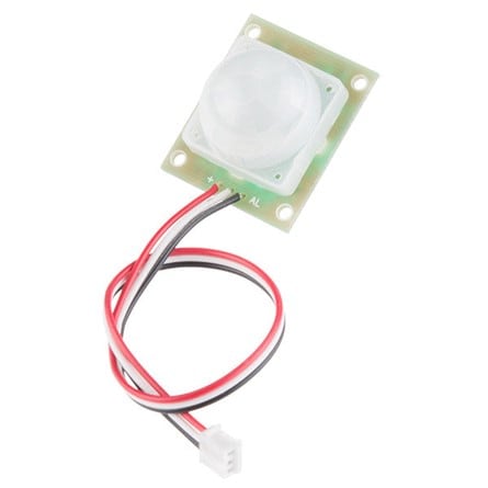
Figure 2: A Passive Infrared (PIR) sensor can be used to detect the presence of a person. (Source: Mouser)
The following procedure should be used to connect the various components of the project (Figure 3).
Figure 3: The pin header layout of the IGaT Curiosity development board. (Source: Microchip)
- Wire a
GNDpin of the Curiosity board to theGNDpin of the relay control board. - Wire the
PA16pin of the Curiosity board to theCONTROL INPUTpin of the relay control board. - Wire a
GNDpin of the Curiosity board to theGNDpin of the relay control board. - Wire the
PB08pin of the Curiosity board to theSIGNAL OUTPUTpin of the PIR sensor. - Wire the
VBUSpin of the Curiosity board to theVCCpin of the PIR sensor.
Setting up the Software Development Toolchain
To develop the firmware for this project, we will leverage the MPLAB X IDE (Figure 4) available to download for free from Microchip.
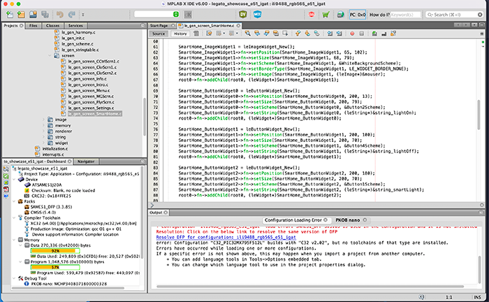
Figure 4: Microchip's MPLAB X IDE is an all-in-one stop for developing firmware for the IGaT development board. Source: GSG
To keep the download size smaller, Microchip packages their various compilers separately from the IDE. Be sure to download the MPLAB XC32 compiler, available for free here. After the software is downloaded and installed, a few housekeeping measures need to be completed before the source code can be edited. From within MPLAB X IDE, we will need to enable a few plugins as well. To do so, follow these steps:
- Click
Tools > Plugins > Available Plugins - Look for
MPLAB Harmony 3 Launcherand place a checkmark in the checkbox. - Look for
MPLAB Harmony Configuratorand place a checkmark in the checkbox. - Click
Install - Click through the wizards until you click
Finish. - Restart the MPLAB X IDE.
In addition, the Edge Impulse platform requires the following dependencies to be installed on your computer:
- Python (version 3.9 or greater)
- Edge Impulse Command Line Interface (CLI) Tool Suite. (NOTE: As of the time this article was written, installing via the npm package manager on Windows is giving errors. The suggested workaround is a PowerShell script available on Edge Impulse's CLI GitHub repository (https://forum.edgeimpulse.com/t/problems-installing-edge-impulse-cli/1954/6))
If you do not wish to use the data forwarder, you can instead write the data coming off the PIR sensor into a .CSV file and upload the raw training and test data via the web browser.
Now it's time to launch the Harmony3 configurator to generate the user interface (UI) and the software stubs that will be used to create the rest of the application.
To do so, click Tools > Embedded > MPLAB Harmony 3 Configurator. This will launch a new window that displays the various software components that make up the project in a graphical format referred to as the Project Graph. From here, click on Tools > Legato Graphics Composer. This will launch as WYSIWYG tool to generate a UI by clicking and dragging certain GUI elements such as buttons, radio boxes, checkboxes, text, graphics, etc. (Figure 5).
The GUI for this project is included and can be repurposed as needed. Microchip has more information on how to use this tool here.
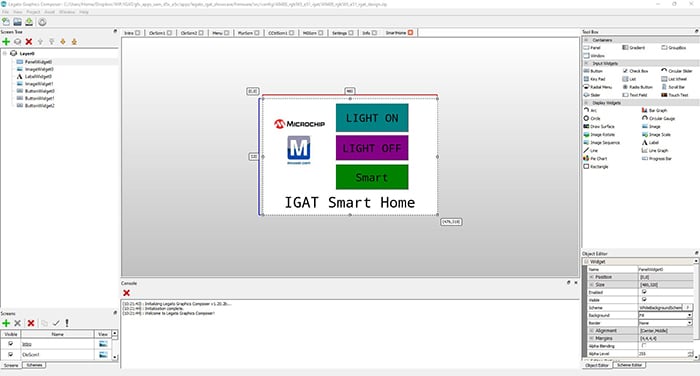
Figure 5: Legato Graphics Composer helps to generate not just touch-friendly GUIs but also application code to provide functionality such as interacting with GPIO pins. (Source: GSG)
Software Development
The codebase for this project is written in C. Before we begin to develop the application's unique software; we must first leverage the services of Edge Impulse to create a machine learning algorithm specific to our PIR sensor and operating environment. For this project, we will consider two operating states that the PIR sensor could be itself in at any given time. These states are:
Person Detected: This is the status indicator that will be triggered when a person passes the PIR sensor for a sufficient period of time, and thus, if the device is set to smart mode, the light will be automatically triggered.Person Not Detected: This is the status indicator that will be sent by the machine learning (ML) algorithm when there is no motion detected by the PIR sensor.
The EI data forwarder allows us to send data from the microcontroller to the training server in ten-second increments. Thus, we will create a few dozen sample sets while standing, walking, and otherwise being within the angle of detection of the PIR sensor for ten seconds for each sample. We will then record another few dozen samples without being in front of the PIR sensor.
Recording the sensor data during both night and day is recommended to account for ambient light and its effect on the sensor. This will make the results more robust to false positives. As with all neural network (NN) training, the more data, the better.
Let's visualize what the data stream will look like for the two states the PIR is set to detect (Figure 6).
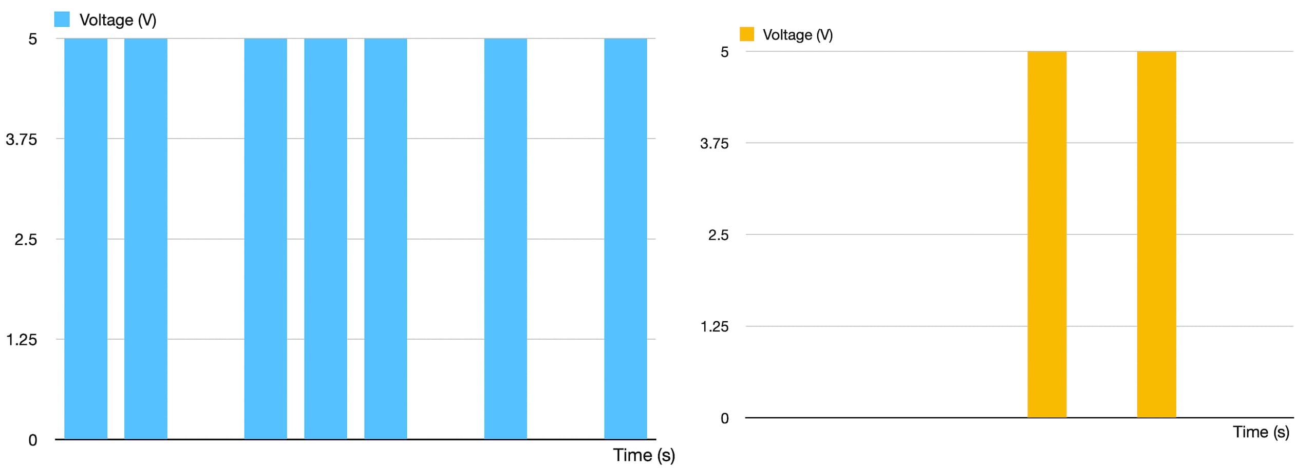
Figure 6: Left: The PIR sensor data when a person in in the room. Right: Data when a person is absent. (Source: GSG)
There are two variables in our dataset. Time is across is the x-axis, and the signal output voltage from the PIR sensor lies along the y-axis. Each dataset is comprised of a ten-second window. The PIR sensor is polled once a second within that ten-second window. Because the sensor output signal should be high only when a person is in range, the more 5V spikes per window should trigger the PERSON DETECTED output for the ML algorithm. Otherwise, the PERSON NOT DETECTED output will result.
After adding additional datasets and retraining the model, we were able to increase overall accuracy from 45% to 80% (Figure 7). The model achieves 100% detection rates but still has some issues with false identifications, likely due to ambient sunlight confusing the sensor. Adjusting the location of the PIR sensor and adding more datasets will likely reduce the false positives.
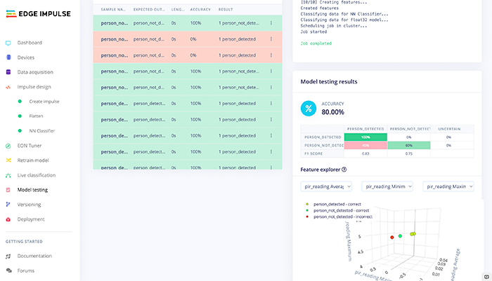
Figure 7: Testing results of the Edge Impulse neural network show 100% accuracy of detection, 80% accuracy of detecting an empty room. Meaning there is a minor potential for false positives. (Source:GSG)
Key Files
The critical files for this project include:
le_gen_screen_SmartHome.c: Contains the code that generates the UI and contains the callback code that triggers when an event occurs (such as screen open, button pressed, etc.)trained_model_compiled.h/.c: Contains the translated PIR person detection model generated by Edge Impulse.ei_run_classifier.c: Contains the classifier code that runs the new data generated by the PIR sensor through the ML algorithm generated by Edge Impulse.
Key Variables and Constants
You might want to be aware of a few variables and possibly tweak them depending on your design choices.
enum currentSystemMode {on, off, smart}: Establishes the three operating modes the device can be in:ON(light on),OFF(light off),SMART(let the PIR control the light status). If you wish to add additional modes, this is the place to add them.
Key Functions
The le_gen_screen_SmartHome.c file contains the initialization code, the main loop, and support functions for the project. The support functions include:
-
SmartHome_ButtonWidgetLightOn->fn->setPressedEventCallback(SmartHome_ButtonWidgetLightOn, event_SmartHome_ButtonWidgetLightOn_OnPressed): PORT_PinWrite(PA16, true); -
SmartHome_ButtonWidgetLightOff->fn->setPressedEventCallback(SmartHome_ButtonWidgetLightOff, event_SmartHome_ButtonWidgetLightff_OnPressed): PORT_PinWrite(PA16, false); -
SmartHome_ButtonWidgetSmart->fn->setPressedEventCallback(SmartHome_ButtonWidgetSmart,
            event_SmartHome_ButtonWidgetSmart_OnPressed):
                currentSystemMode = smart;
Final Assembly
Caution: Be extra careful when working with alternating current (AC). You should never modify a project while it's plugged into an electrical outlet. Instead unplug the device, make any adjustments necessary, and check that the wiring and connections are secure before plugging it back in.
To complete the assembly to test out the project, we need to do the following:
- Plug a desk lamp into the relay control board AC outlet.
- Plug the relay control board into a nearby wall AC outlet.
- Mount the PIR sensor in a way that it avoids direct sunlight to the greatest extent possible.
- Plug the Curiosity board into a DC power supply with a USB interface.
- Plug the DC power supply into a nearby AC outlet.
Project in Action
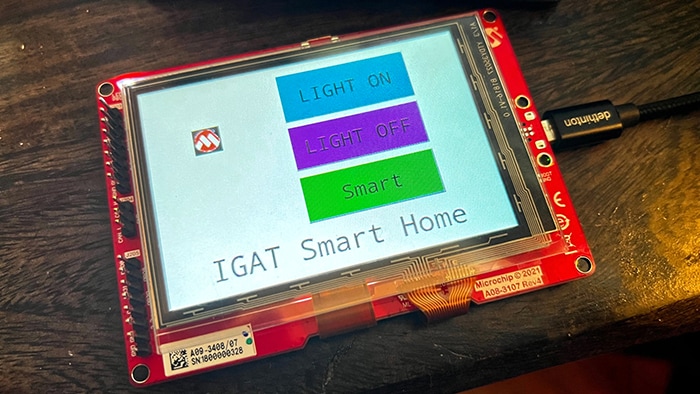
Figure 8: The IGaT Smart Home display in operation. Source: GSG
With the project assembled and firmware installed, it's time to verify the operation.
Pressing the LIGHT ON button will cause the relay to energize (Normally Open N.O.) and thus turn the desk lamp on.
Pressing the LIGHT OFF button will de-energize the relay (N.O.), causing the desk lamp to turn off.
Pressing the SMART button will turn control of the light over to the automation algorithm. It will keep the light on for ten minutes and then turn off if there hasn't been further detection of a person. Energy saver! Pressing any button while the device is in the smart mode will take the device out of smart mode.