Remote Dimming of LEDs to Very Low Light Levels with a Single-stage Off-line Driver
Dimmable LED drivers have stability problems at very low light levels. This article will examine the reasons and propose a solution to the problem.
The article will not cover triac dimming – instability at low settings is due to different mechanisms.
Dimming methods using a communication scheme to set LED current include DALI, 0-10V, Zigbee, and Powerline Carrier control. A signal received at the LED driver sets a reference current, and a control loop adjusts scaled LED current to match the reference. Tight control is required so that the light from adjacent fixtures appears the same.
We had been puzzled by flicker and “shimmer” that appears at low light levels.
Single-stage power factor correction
If a two-stage power converter is used, the low light level instability is never seen. The first stage (boost or PFC-Flyback) establishes a relatively steady voltage, and the second stage (usually inverse buck) closely regulates the current in the LEDs. The two-stage approach uses more parts and is less efficient than a single-stage converter.
For cost reasons, the single-stage PFC-Flyback converter is usually selected.
Figure 1 Typical PFC-Flyback LED driver with external control

The Problem
Dimming over at least a two-decade range is desired. Incandescent lamps have no problem delivering this range – they become dramatically less efficient at low power levels, so the power range needed for the two decade light range is fairly narrow. If 40% of voltage or current is delivered, light output drops to about 1%. Unfortunately, this sets the market’s expectations for LEDs.
LEDs have a much more linear response, and their efficacy actually increases at low currents. The eye can discern 5% differences between adjacent sources, and it responds to the percentage difference, not the absolute light level. This will require very tight control of the current, and the accuracy required gets even tighter at low light levels. Primary side control cannot be used if dimming to 1% is required.
LEDs have no self-filtering mechanism like incandescents. The thermal mass of the filament in a light bulb is a satisfactory filter for the AC line, but LEDs require external filtering. The usual solution is a large electrolytic capacitor directly across the LEDs, and it works well.
The size of the electrolytic is set by the requirement for ripple. If the current ripple is less than about 10% rms (about 28% p-p) the light quality is perceived the same as for pure DC. (Also, the Energy Star label requires a statement on the lamp if ripple exceeds 10%.)
LEDs have a dynamic resistance (slope resistance) of about 1/10 of the apparent V/I resistance. Figure 2 shows the V-I curve for a typical LED.
Figure 2 Typical LED V-I Characteristic showing Slope Resistance (dV/dI) varying with current

So, for ripple less than 10% RMS, the capacitor must hold the voltage across the LEDs within about 1%. The value needed is:
C = (0.707 * 100 * ILED) / (2π * 120Hz * Vstring)
The capacitor is also part of the control loop. The capacitor and LED dynamic resistance set a control pole at about 30Hz. So it adds a phase lag of 45 degrees and reduces loop gain by 6dB at that frequency. We’ll get back to this later…
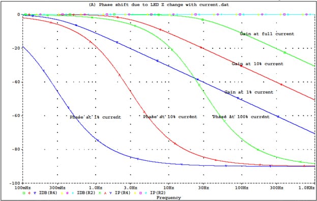
The graph below details gain and phase shifts due only to the LED-capacitor pole.
Figure 3 Shift of Control Pole with LED Current due to increasing dynamic resistance

Notice that the dynamic impedance of the LED increases as current is reduced. Unfortunately, this shifts the control loop pole to the left. At 10% current, the corner frequency is about 3 Hz. At 1% current it’s about 0.3Hz. Note that the typical control loop for a PFC stage has a crossover frequency between 3Hz and 20Hz.
It’s not reasonable to design a control loop with a movable pole of this range. The only possible solution is to design for a crossover in the 0.03 - 0.1 Hz range – and the loop would be very, very sluggish.
The Solution
There is another solution. It involves more parts, but efficiency is only slightly affected, and costs are still lower than the 2-stage driver.
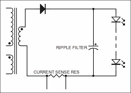
The current into BOTH the capacitor and LED string can be measured. This is the converter output current.
Figure 4 Eliminating phase shift due to movable pole

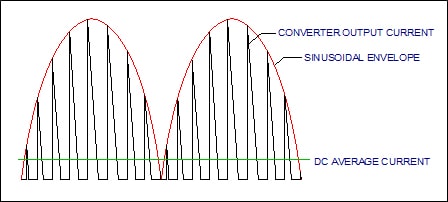
However, the current supplied by the PFC-Flyback converter is in triangular pulses, and the pulses are modulated by a 120Hz sine wave with a DC offset. The DC offset is what we are trying to measure. The high frequency and 120Hz components must be filtered out.
The pulsed current would also greatly increase the dissipation in the current sampling resistor.
The high frequency current feeding the film capacitor has the shape and envelope shown in Figure 5.
Figure 5 Output current from PFC-Flyback Converter (HF period exaggerated)

The RMS current of the sawtooth component is huge. At low line, for a wide-range converter (90Vac to 305Vac) the current at the peak is over 8 times the average DC output current, and the RMS current over twice the average DC output current. The sensing resistor would dissipate 4 times the power it would see if it were after the electrolytic capacitor.
To fix this, a small film or ceramic capacitor can be placed on the converter output. Not much capacitance is required, but the capacitor’s ESR must be low and the RMS current capability must be adequate. Several capacitors in parallel may be required. A small inductor in series with the current sampling resistor may also be useful.
To calculate the film capacitor value, we will assume a diode duty cycle of 50%, typical of worst-case low line operation at the waveform peak.
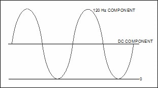
The film capacitor has a negligible effect on the twice-line-frequency component. This must still be removed.
Figure 6 Twice-Line-Frequency and DC components of Figure 5 (sawtooth component filtered out)

The heating effect of the sine component in the current sampling resistor is small, since it’s a small fraction of the total current. The relationship of DC and 120Hz components is constant – the AC peak-to-peak is twice the DC, so its RMS value is 0.707 of the DC current (LED current). The RMS currents add in the usual way, square root of sum of the squares:
Irms = √(Idc^2 + (0.707 * Idc)²) = √(1.5) * Idc = 1.225 * Idc.
Dissipation in the current sampling resistor would still be significantly higher than with the LED DC current measurement, rising by a factor of I2.
P[120+dc] = Pdc * I² = Pdc * (1.225)² = 1.50 Pdc.
But this is a lot better than with the switching frequency component present.
For the control loop, the 120 Hz component can be filtered out with a simple R-C filter made up of small SMT parts. It would have stable gain and phase shift characteristics that only varied with frequency, not with the load current. The 6 db breakpoint can be set the same as for the full LED DC current measurement, or slightly lower in frequency.
The final output circuit schematic is shown in Figure 7. Values are typical for a 60 Hz line frequency with an 18-LED string at 350mA.
Figure 7 – Output stage with stable control breakpoints
