Rotary Encoders Critical to Successful Motion-Control Implementation
In most motion- and motor-control designs, it's necessary to know the position, direction and speed of the motor shaft. This is especially true with brushless-DC (BLDC) motors, which are increasingly being used due to their efficiency and controllability, but which need the system controller to "know" precisely when to energize and de-energize the motor's coils to maintain proper rotation.
To determine the motor's parameters in real time, a shaft-mounted encoder is used. The encoder is an electromechanical component that translates the rotation of the shaft to electrical signals, which can then be fed back to close the loop via the motion controller. In this way, the system can control motor-shaft position, velocity, velocity profile, and torque, and also monitor for stalls or other fault conditions. Once the shaft position and direction of motion are known, the electronics can use analog circuitry or digital processing to determine the speed and even acceleration of the shaft motor. (Remember: Speed is the time derivative of position; acceleration is time derivative of speed.) Some installations mount the encoder further along the motion-transmission path, but this brings subtle issues of backlash, slop, flexing, and other mechanical problems that must be carefully factored into the design.
Although the sensing of the motor position is straightforward in concept, it is challenging in practice due to the difficult operating environment of most motors, ranging from modest vibration to start/stop impact, and more. In addition, users have differing priorities for accuracy, resolution, ruggedness and, of course, cost.
Note that not all motors need encoders. If position or speed accuracy is not critical— such as for a washing machine drum— it is possible to use "sensorless" motor control. (See Sidebar: "What About Sensorless Designs?")
Encoder Technologies Offer Trade-offs
To meet these needs, three encoder technologies are most commonly used based on optical, magnetic (also called resolver), and capacitive principles. Each of these is a non-contact device, so there are no issues with friction or wear, as could occur with simpler contact-type brush encoding.
Resolution is the primary encoder parameter to consider. Standard encoders offer between 48 and 2,048 pulses per revolution (ppr). Higher counts offer greater precision, but also require a more costly encoder and place additional calculation and processing burden on the system controller or digital processor that is closing the loop. As with all high-resolution devices, the excess precision can be rendered useless due to noise, vibration, and jitter in shaft position. The encoder output then goes to circuitry, which translates the raw signals into usable format and data, and then to a system controller. In some implementations, the translation is done by the system controller itself.
Optical encoders are based on a glass or plastic disk ("code wheel") with two sets of slots around the periphery. An LED light source and photodetectors are located on opposing sides of the disk. As the disk turns, the on/off passing of light through the slots provides pulses that indicate both position and direction of rotation. An optical encoder typically needs just a single low-voltage DC supply between 20 and 40 mA for operation.
Some optical encoders include only the electronics, while the user supplies the actual code wheel; other vendors offer the code wheel as an option, and larger code wheels ease achieving meaningful higher resolution. The encoder plus its code wheel require care in the mounting arrangement and alignment, and the code wheel's center opening must be sized to fit the motor shaft.
An example of an encoder with an optionally available code wheel is the HEDS-9040 and similar HEDS-9140 series of three-channel optical-incremental-encoder modules from Avago Technologies. Each module consists of an LED source with lens, as well as a detector IC enclosed in a small plastic package, and supports resolution up to 2000 ppr via TTL-compatible outputs.

Figure 1: The Avago Technologies HEDS-9040/9140 series of three-channel optical encoders can work with resolutions up to 2000 ppr, and the vendor offers a family of suitable code wheels as well, with different diameters to enhance the resolution readout.
In addition to the two output tracks, this encoder provides a third track for indexing, where the encoder generates a pulse once per revolution. Indexing is needed in some applications to align the motor shaft position to a known starting point, but may also require that the encoder and shaft be mechanically aligned in production as well, depending on the product design. Figure 2 shows the internal electronics of the HEDS-9040/9140 encoders, including LED, lens, photodiodes, and output comparators, plus the interposed code wheel.
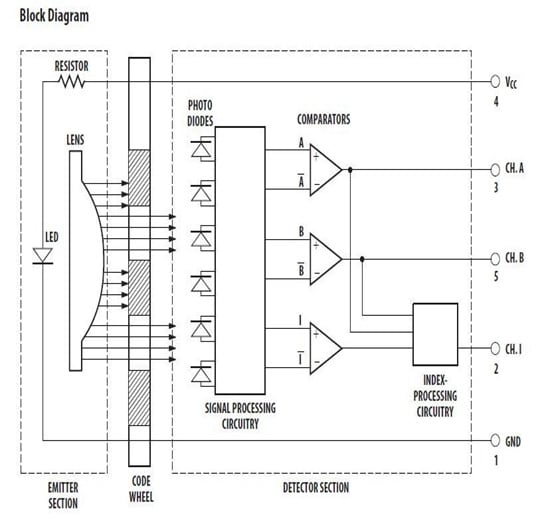
Figure 2: With the HEDS-9040/9140 optical encoders are a single-LED, multiple phototransistors, and circuitry for "squaring up" the phototransistor output signals; the code wheel is physically placed between the LEDs and the phototransistors.
Avago also offers AEDR-850x reflective encoders, which use a disk with reflective slots instead of transparent slots. This allows for a much thinner design since the LED source and photodetectors are located on the same side of the disk. The trade-off is lower maximum resolution, but that limitation is not an issue in many applications. This encoder is in a surface-mount leadless package measuring just 3.95 (L) Ô 3.4 (W) Ô 0.9562 mm (H), making it well-suited for applications where size and space are primary concerns.
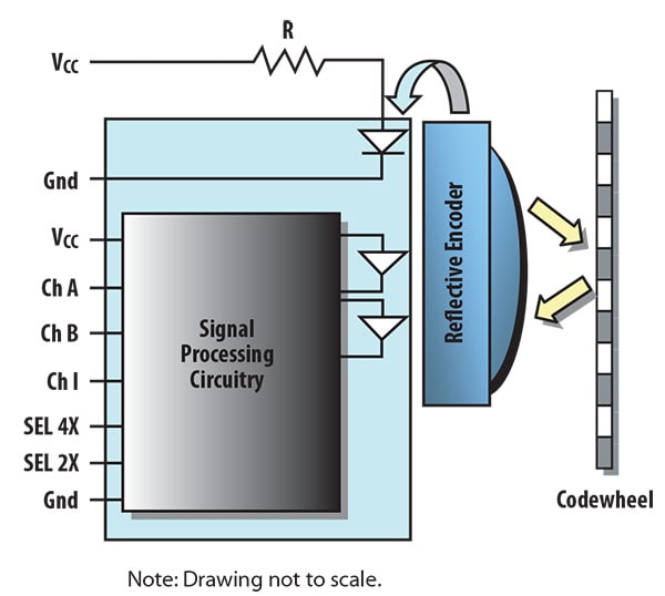
Figure 3: For an even-thinner optical encoder solution, the code wheel with transparent slots is replaced by one with reflective slots, such as the Avago AEDR-850x; this puts the light source and receivers on the same side and results is an encoder which is less than 1 mm thick. (Source: Avago Technologies)
Encoders using the optical approach are used extensively and quite successively, but they have to be matched to the harshness of the application. Dirt, oil and other containments, all of which are often present in the installed environment, can interfere with the disk and slots, and thus the encoder output. Further, the LED brightness can dim to half within 10,000 to 20,000 hours (roughly one to two years) and even LEDs eventually burn out. Some optical encoders use a plastic disk for lower cost, but it may warp at higher operating temperatures (a common situation in many industrial-motor installations), so an encoder with a more costly and more fragile glass disk may be needed. Regardless, the optical encoder is often a first choice that designers consider, due to its small size, low cost and the many available vendors and models.
The magnetic or resolver encoder uses a pair of special transformer-like windings, with a primary one on the shaft and a secondary on the surrounding pickup winding. A sinusoidal waveform is used to excite the primary winding, and this excitation induces a sine output on the secondary side. This secondary-side output signal is then demodulated with respect to the primary-side waveform. The phase difference between the two waveforms indicates the relative position of the shaft with respect to the fixed winding. One example of a contact-less magnetic encoder is ams' AS5145 12-Bit Programmable Magnetic Rotary Encoder. It is a system-on-chip, combining integrated Hall elements, analog front end and digital signal processing in a single device, with available evaluation/demo boards.
Figure 4: ams' AS5145 12-Bit Programmable Magnetic Rotary Encoder is a system-on-a-chip (SoC).
As basic transformer windings, encoders using this design are rugged, reliable, and consistent over a wide temperature range, but they require excitation and demodulation circuitry, which requires more power than the optical approach. The encoder is also relatively costly and large compared to the optical approach, and the installation must be planned to allow for both sets of windings. However, the encoder is "complete" and does not require a separately supplied code wheel or similar add-on.
A third alternative is the capacitive encoder, an adaptation to the capacitive-sensing operating principles of the standard linear-position encoder, developed for vernier calipers more than 30 years ago. It uses patterns of bars or lines, with one set on the fixed element and the other set on the rotating element, to form a variable capacitor configured as a transmitter/receiver pairing. As the shaft rotates, an ASIC-based electronics circuit in the encoder counts the line changes and also interpolates to find the position of the encoder and direction of rotation. This technique is not affected by dust, dirt, or temperature, and there is no LED to dim or burn out; operating current is under 10 mA.
A third alternative is the capacitive encoder, an adaptation to the capacitive-sensing operating principles of the standard linear-position encoder, developed for vernier calipers more than 30 years ago. It uses patterns of bars or lines, with one set on the fixed element and the other set on the rotating element, to form a variable capacitor configured as a transmitter/receiver pairing. As the shaft rotates, an ASIC-based electronics circuit in the encoder counts the line changes and also interpolates to find the position of the encoder and direction of rotation. This technique is not affected by dust, dirt, or temperature, and there is no LED to dim or burn out; operating current is under 10 mA.
In addition to optical, magnetic, and capacitive encoders, Hall-effect sensors can be used for shaft encoding. While effective and reliable, they are generally suitable only for relatively low-accuracy/resolution determination of shaft position, such as for indicating the passage of gear teeth on a driveshaft.
Encoder Outputs and Determining Direction
All of the encoder designs discussed are incremental types, meaning they indicate relative position of the shaft, but not its absolute position. Thus, at "power-up" the system will not know the angle or position of the shaft. The alternative approach is to use an absolute encoder, a more complex component that reports angle as soon as power is applied. Absolute encoders are more commonly needed on shafts that do not rotate a full circle or more, such as instrument bearings used to determine the angle of tilt in a surveyor transit. However, these are not conventional motor-rotation situations, and even on these instruments, the absolute encoders face competition from low-cost MEMS accelerometers.
Optical encoder vendors have fortunately standardized on encoder output-signal formats, which eases choosing among the different technologies. The "raw" outputs of the encoder are the primary or in-phase signal, often called the A signal, and a quadrature 90° signal offset from the primary track, often called the B signal.
For rotation in one direction, A leads B by 90°, for counter-rotation, B leads A by 90°. Thus, by looking at the two signals and their relative phase, the direction of rotation is determined. The encoder's associated electronics produce "count-up" pulses or "count-down" pulses that the system controller can then use to determine relative position, speed and even acceleration (the latter requires more real-time processing, and may be sensitive to signal jitter).

Figure 5: An optical encoder generates two signals in quadrature; by looking at their relative phase difference, the system can determine the direction of rotation. Not shown is the index pulse, if any. (Source: Robotoid, Robot Builder's Bonanza, 4th Edition - Application Notes & Bonus Projects; released under Creative Commons 3.0 SA License)
Increasingly, motor-shaft sensing designs that may have used absolute encoders in the past now use incremental encoders with the third index channel, to determine the shaft position on power-up if needed. This works because knowing the absolute position on start-up is not important in many applications, while the relative position and motion information is critical and the once-per-revolution index pulse is sufficient.
While the encoder's basic output A, B and index signal functions are standardized, these signals are provided at different levels and compatibilities depending on the specific encoder model. Users can choose among TTL, CMOS, single-ended, and differential A, B, and index signals, to match the interface requirements of the electronics that connect to the encoder output. Most vendors offer many of their encoders with a choice of interface options, so the user can first pick a unit with the needed encoding performance and then select the appropriate electrical interface.