For a Happier Office, Utilize Intelligent Commercial Lighting
A Lighting Solution with Variable Color Temperatures Designed for Human Circadian Rhythm
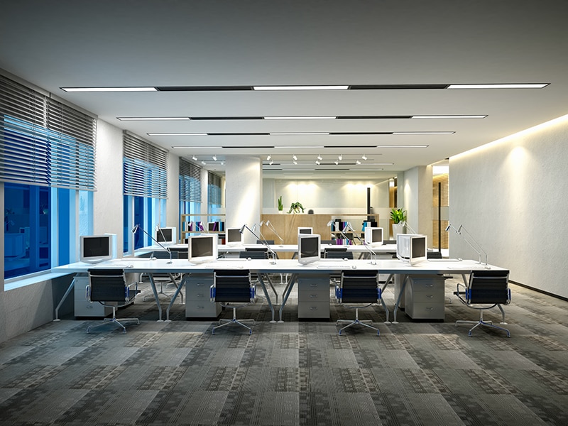
Image Source: Furkan Telliogluu/Shutterstock.com
By Anthony Dong, Mouser Electronics
Published August 18, 2021
The need for smart lighting is growing, as its market size is expected to reach around $36.84 billion (USD) by 2026. Some employers have already upgraded from fluorescent light bulbs to smart LED lighting systems, which offer customizable color temperatures and intensities. The reason these systems are becoming more popular is that LEDs save energy. LED lighting also has many health benefits in certain conditions.
Studies have shown that different light temperatures affect the human body differently. Warmer color temperature tends to be relaxing, while cooler color temperatures are likely to increase concentration. Therefore, it would be advisable to set a cooler color temperature in the office to help keep employees focused and productive. To maximize the benefits of different color temperatures, the system should dynamically control color temperatures and lighting intensity over time, enhancing physical and behavioral health.
Hence, this LED lighting project does exactly that. This lighting system automatically adjusts to different color temperatures and intensities based on the time of day. It can also detect insufficient lighting or human movement in the surrounding environment and change accordingly. The rest of this article will provide links to project code and schematics, and instructions on development environment settings and basic operations.
Project Materials and Resources
We recommend gathering the following project materials before getting started:
- Bill of Materials
- Code and schematic files
- Hardware
- Accounts and software
Project Bill of Materials (BOM)
Access the project’s BOM on Mouser.com for these required components:
- 579-DM182028–Microchip PIC18F47K42 Curiosity Nano Development Board
- 579-AC164162–Microchip Curiosity Nano Base for Click Boards
- 932-MIKROE-3601–MIKROE Ambient 7 Click Board
- 932-MIKROE-1990–MIKROE RTC 5 Click Board
- 932-MIKROE-4059–MIKROE Motion 2 Click Board
- 556-ATQT7-XPRO–Microchip Touch Sensor QT7 Xplained Pro Development Board
- 416-CSB172G026527900–New Energy 2700K to 6500K Linear Tunable LED Bar
- 675-SLE24S4803B01–SL Power Wall Mount AC Adapters (48.0V, 0.5A)
- 675-KT1001US–SL Power NA Contacts for AC Adapters
Project Code and Schematic Files
Hardware
- Soldering iron
- Jumper wire
- Solder
- Breadboard
- Digital Multimeter (optional)
- Oscilloscope (optional)
Accounts and Software
- MPLAB X Integrated Development Environment (IDE)
- MPLAB XC8 Compiler
- MPLAB Code Configurator (MCC; installed in MPLAB X IDE as a plugin)
Project Technology Overview
The intelligent commercial lighting system is an intermediate-to-advanced level project for those with experience in C programming language, soldering and wiring skills, and embedded systems development. The instructions provided have been completed using Windows 10 64-bit.
For this project, we have used the following products and technologies, described in the below sections:
- Microchip PIC18F47K42 Curiosity Nano Development Board
- MIKROE RTC 5 Click Board
- MIKROE Ambient 7 Click Board
- MIKROE Motion 2 Click Board
- Microchip Touch Sensor QT7 Xplained Pro Development Board
- MPLAB X IDE
Microchip PIC18F47K42 Curiosity Nano Development Board
The Microchip PIC18F47K42 Curiosity Nano Development Board (Figure 1) comes equipped with the Microchip PIC18F47K42. This chip integrates an abundant set of independent peripherals, intelligent analog peripherals, and large Flash memories. The on-board debugger makes it even easier for developers to prototype their products. By default, this development board provides access to I2C, SPI, UART, GPIOs, ADCC (Analog-to-Digital Convert with Computation Module), and PWM, allowing developers to design their projects flexibly. Enhanced by MPLAB X, this development board can be loaded with many auto-generated libraries for MIKROE Click Boards.
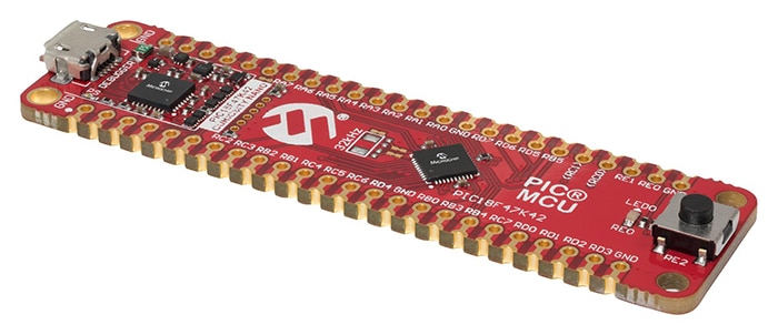
Figure 1: Microchip PIC18F47K42 Curiosity Nano Development Board. (Source: Mouser Electronics)
MIKROE Click Boards
We will use an RTC5 Click for this project (Figure 2), which carries MCP79510, a real-time clock/calendar with an SPI interface (mikroBUS MISO, MOSI, SCK, and CS pins), along with a programmable interrupt for system output. This module serves the purpose of providing real solar time for the MCU because it automatically compensates for leap years and months shorter than 31 days. A coin-cell Lithium polymer battery is used as backup power.
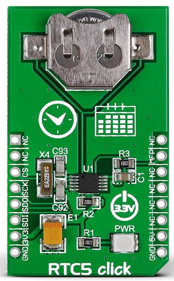
Figure 2: MIKROE RTC 5 Click Board. (Source: Mouser Electronics)
Ambient 7 Click (Figure 3) will be used to detect the intensity of ambient light, which features an accurate light-intensity sensor labeled as SFH 5701 A01, made by Osram Opto Semiconductors. It offers a high measurement accuracy in a wide range of the actual light intensity. The Ambient 7 Click outputs an analog voltage, which the ADCC module will sample on the MCU.
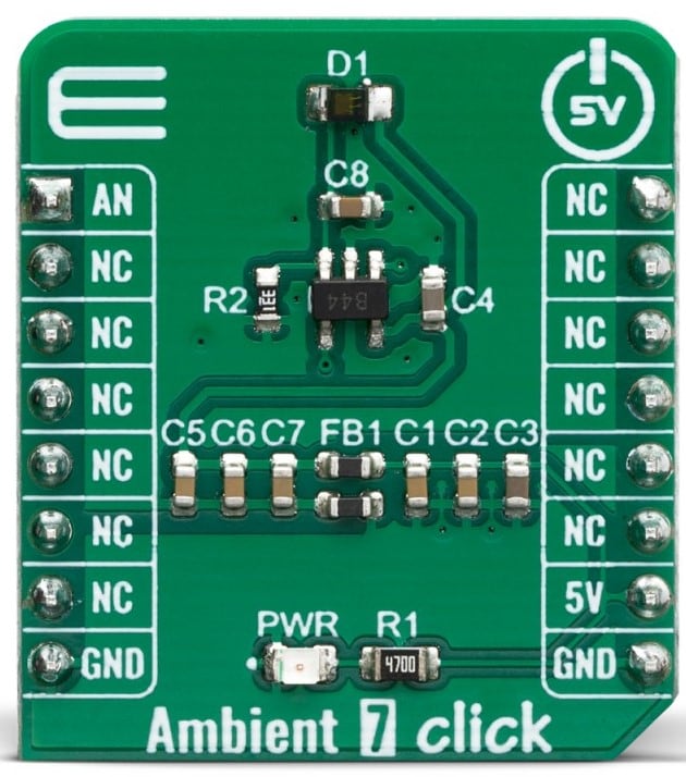
Figure 3: MIKROE Ambient 7 Click Board. (Source: Mouser Electronics)
Motion 2 Click (Figure 4) will be used to detect human movements, integrated with EKMC1607112, PIR motion sensor from Panasonic Corp. Toshina also has a TLP241A photorelay that provides a reinforced galvanic isolation for the external signals used to drive some external high-power electronic equipment when motion is detected. However, we will not use that for our project. The Motion 2 Click outputs an interrupt signal when motion is detected, which will trigger the IOC (Interrupt on Change) subroutine programmed in the MCU. To use this module, the EN pin needs to be set low.
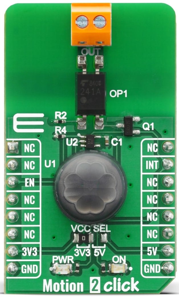
Figure 4: MIKROE Motion 2 Click Board. (Source: Mouser Electronics)
Microchip Touch Sensor QT7 Xplained Pro Development Board
This board (Figure 5) can evaluate self-capacitance touch—robust, water tolerant to the highest extend. It includes one board with one self-capacitance slider and two self-capacitance buttons, along with eight LEDs providing feedbacks for the buttons and the slider. We will only use the two buttons for this project, as our 8-bit MCU has limited GPIO pins.
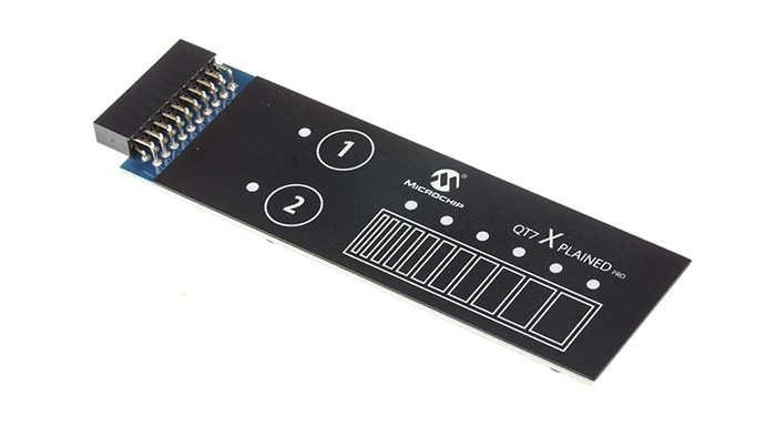
Figure 5: Microchip Touch Sensor QT7 Xplained Pro Development Board. (Source: Mouser Electronics)
MPLAB X IDE
Microchip Technology MPLAB® X Integrated Development Environment (IDE) is an expandable, highly configurable software program that incorporates powerful tools to enable designers to discover, configure, develop, debug, and qualify embedded designs for most Microchip Microcontrollers (MCUs) and Digital Signal Controllers (DSCs). MPLAB X IDE works seamlessly with the MPLAB development ecosystem of software and tools, many of which are completely free. For this project, we will heavily utilize MCC and downloadable libraries in the MPLAB X IDE.
Developing the Embedded Software
In the following sections, we will walk the readers through the process of developing the embedded software for the intelligent commercial lighting system:
- Install MPLAB X IDE (v5.50 or above)
- Install MPLAB XC8 Compiler (v2.3.2 or above)
- Install MCC (v4.2.1 or above with core v5.2.1 or above) as a plugin in MPLAB X IDE
- Create a standalone project for PIC18F47K42
- Install MikroElektronika Click Library (v1.1.2 or above) in MPLAB X IDE
- Install mTouch Capacitive Sensing Library (v2.90.1 or above) in MPLAB X IDE
- MCC Settings
- Generate example code from the libraries
Install MPLAB X IDE
- Download link: https://www.microchip.com/en-us/development-tools-tools-and-software/mplab-x-ide#tabs
Install MPLAB XC8 Compiler
- Download link: https://www.microchip.com/en-us/development-tools-tools-and-software/mplab-xc-compilers#tabs
Install MCC
- Figure 6: Tools → Plugins
- Figure 7: Select MPLAB Code Configurator and install
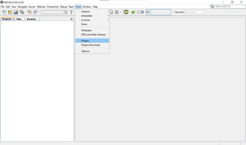
Figure 6: MPLAB X IDE plugin installation. (Source: Mouser Electronics)
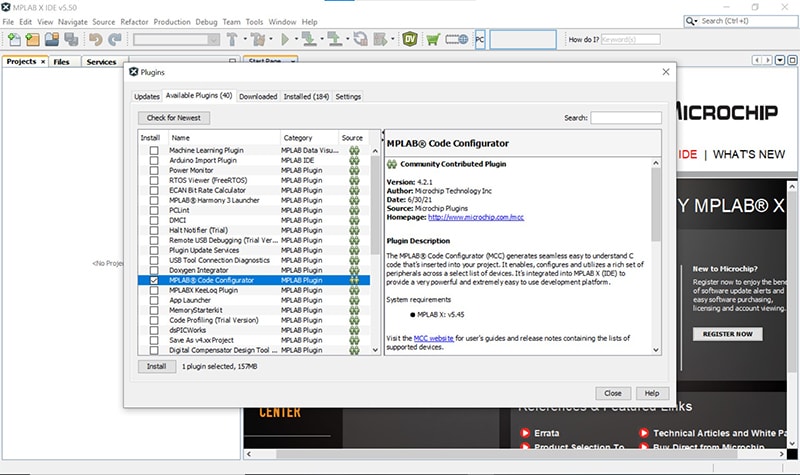
Figure 7: MCC installation. (Source: Mouser Electronics)
Create a Standalone Project
- File New Project → Microchip Embedded → Standalone Project → Next
- Family: Advanced 8-bit MCUs (PIC18) → Device: PIC18F47K42 → Tool: Choose MCU → Next
- Choose XC8 as compiler → Next
- Name your project → Finish
Library Installation
- Open MCC
- Go to Versions [MCC] on the bottom left
- Figure 8: Find MikroElektronika Click Library and mTouch Capacitive Sensing Library and Click to load
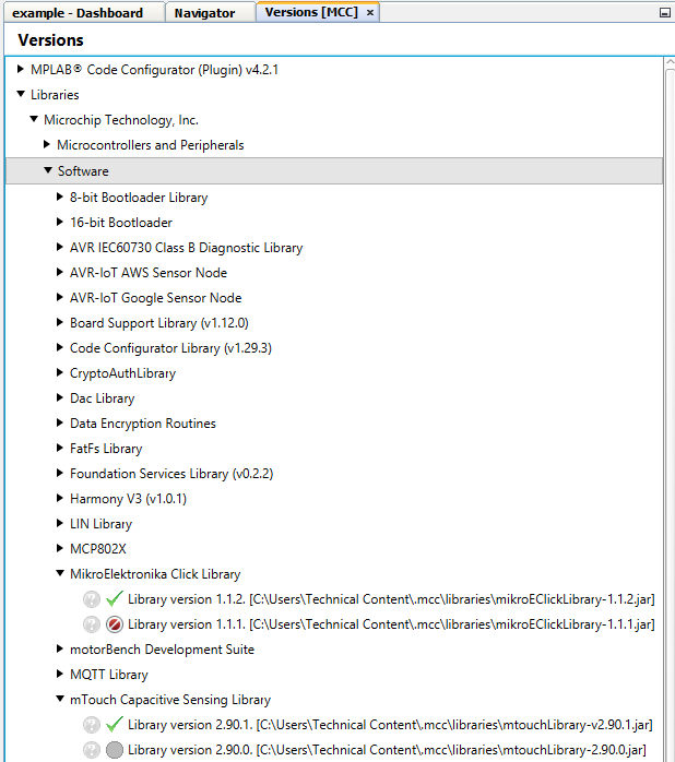
Figure 8: Load MikroElektronika Click Library and mTouch Capacitive Sensing Library. (Source: Mouser Electronics)
- Figure 9 to Figure 12: Above Versions [MCC], go to Device Resources and add mTouch, PWM6, PWM8, TMR2, and RTC5 (TMR1 and TMR3 are also added but not used; they can be used to detect the duration of a button press to handle various operations)
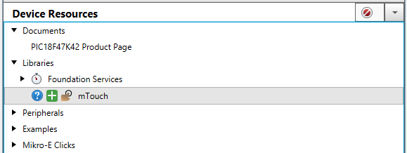
Figure 9: Add mTouch. (Source: Mouser Electronics)
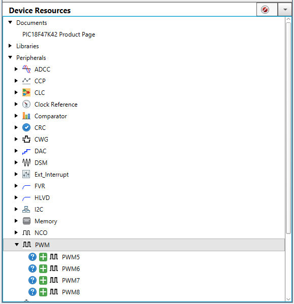
Figure 10: Add PWM6 and PWM8. (Source: Mouser Electronics)
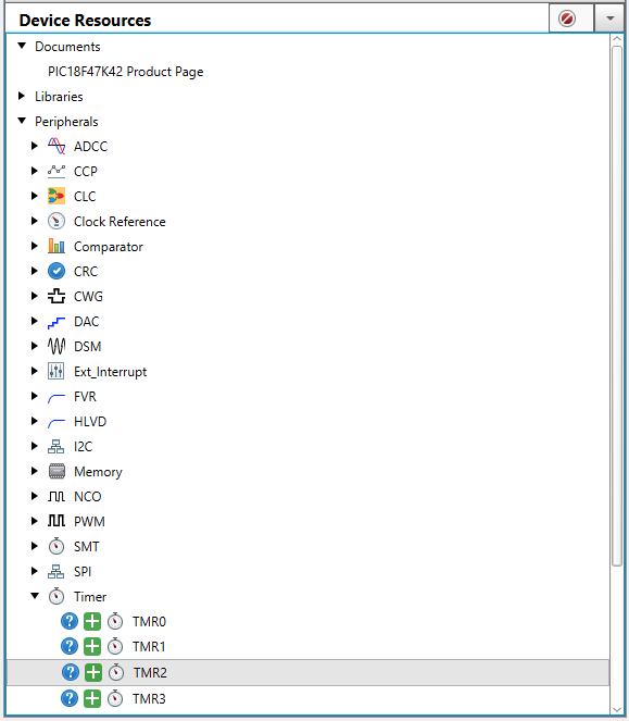
Figure 11: Add TMR1, TMR2, and TMR3. (Source: Mouser Electronics)
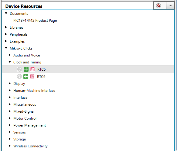
Figure 12: Add RTC5. (Source: Mouser Electronics)
MCC Settings
Follow the bullet points below, as they will help to set up the development environment correctly.
- Figure 13 shows System Module settings. We will choose HFINTOSC as our oscillator because it will provide us with the 64MHz clock. We need such a high-frequency clock because the touch bar needs to be sampled at a fast rate.
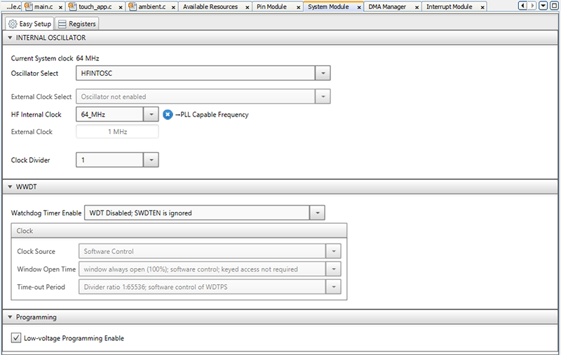
Figure 13: System Module settings. (Source: Mouser Electronics)
- Figure 14 and Figure 15 You will need to make sure all pins are properly assigned and configured using the Grid View Pin Manager and Pin Module.
- Assign RA1 to ANx to sample data from Ambient 7 Click.
- Assign RD0 and RD1 to PWM6 and PWM8, respectively.
- Assign RB5 to GPIO input in the Pin Manager and set the Interrupt on Change (IOC) to positive-edge in the Pin Module Settings to detect interrupt signals from Motion 2 Click.
- Assign RD2 to GPIO output to send EN signal to Motion 2 Click.
- Assign RB2 and RD5 are assigned to GPIO output for the feedback LEDs on the touch bar.
- RE3 is by default assigned to MCLR
- Assign RD4 to the CS pin on RTC 5 Click.
- Assign RC4, RC5, and RC6 to SDO, SDI, and SCK, respectively, as part of the SPI interface between MCU and RTC 5 Click.
- Assign RA2 and RD7 to the touch sensors (CS pins) on the touch bar (though they are by default output, you need to change them to input in the Pin Module manually; also, make sure they are in analog mode).
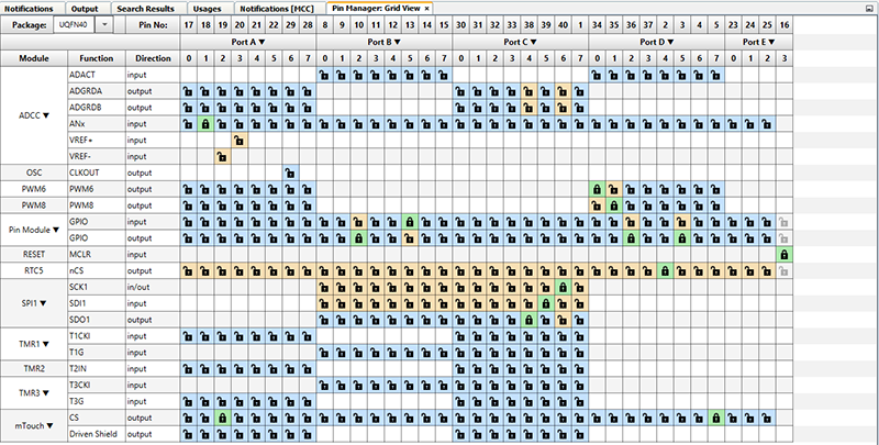
Figure 14: Pin Manager. (Source: Mouser Electronics)
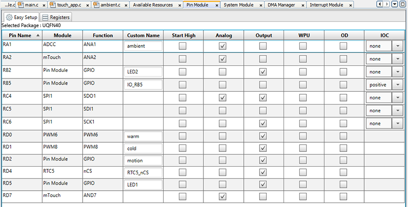
Figure 15: Pin Module settings. (Source: Mouser Electronics)
- Figure 16 shows Interrupt Module settings. Interrupts for TMR1, TMR3, and ADCC are automatically configured if the previous instructions are followed. The only interrupt that needs to be manually configured is Pin Module IOC interrupt. Simply tick the enable box.
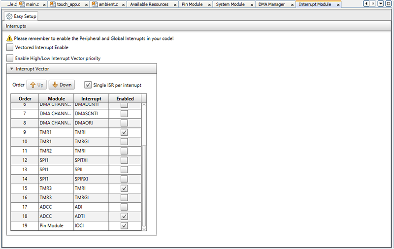
Figure 16: Interrupt Module settings. (Source: Mouser Electronics)
- Figure 17 shows TMR2 settings. The clock source needs to be set to FOSC/4 to use PWM6 and PWM8. We also need to set the prescaler to 1:128 because our LED drivers only detect PWM signals from 100Hz–1000Hz. By doing that, we will obtain PWM signals at around 500Hz.
Figure 17: TMR2 settings. (Source: Mouser Electronics)
- Figure 18 shows PWM6/PWM8 settings. Choose Timer2 as the timer and put any value as duty cycle because it can be changed later in the code.
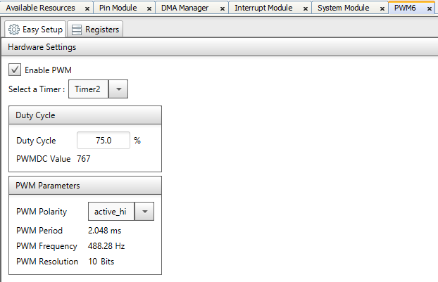
Figure 18: PWM6 and PWM8 settings. (Source: Mouser Electronics)
- Figure 19 to Figure 20 show mTouch settings.
- As Figure 19 indicates, we should click on Create New Buttons. Two buttons need to be created and named Button1 and Button2, respectively.
- As Figure 20 indicates, after the buttons are created, you will see them in the Buttons dropdown menu. Make sure Consecutive Decodes are set to 32.
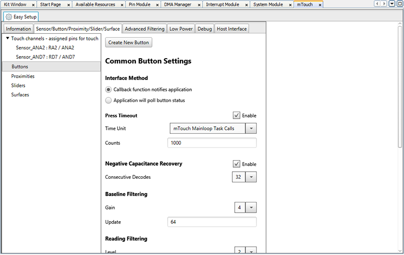
Figure 19: Create new buttons. (Source: Mouser Electronics)
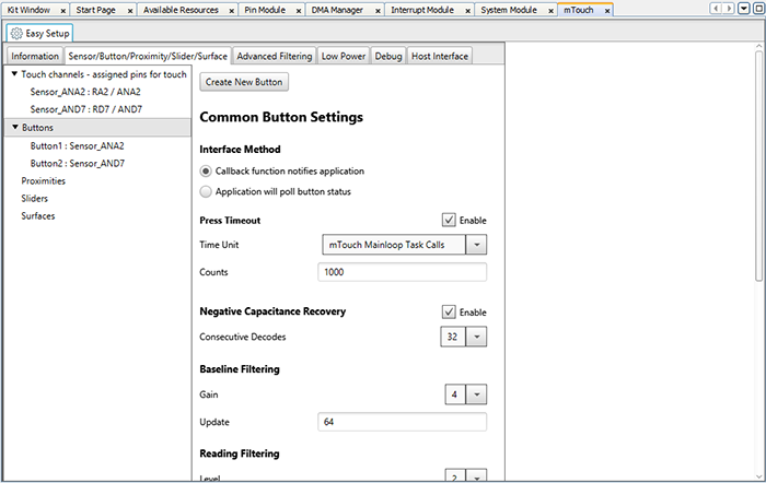
Figure 20: Set consecutive Decodes to 32. (Source: Mouser Electronics)
- Figure 21 to Figure 22 show TMR1 and TMR3 settings. We choose LFINTOSC as our clock source, and the prescaler is set to 1:2 so that we can input 4s in the time period. These timers are supposed to detect touches on the touch bar that are longer than 3 seconds. However, in this project, we are not using this functionality; we simply provide the settings here for the sake of compatibility, so feel free to experiment with them.
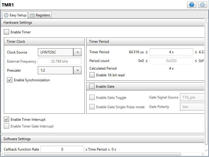
Figure 21: TMR1 settings. (Source: Mouser Electronics)
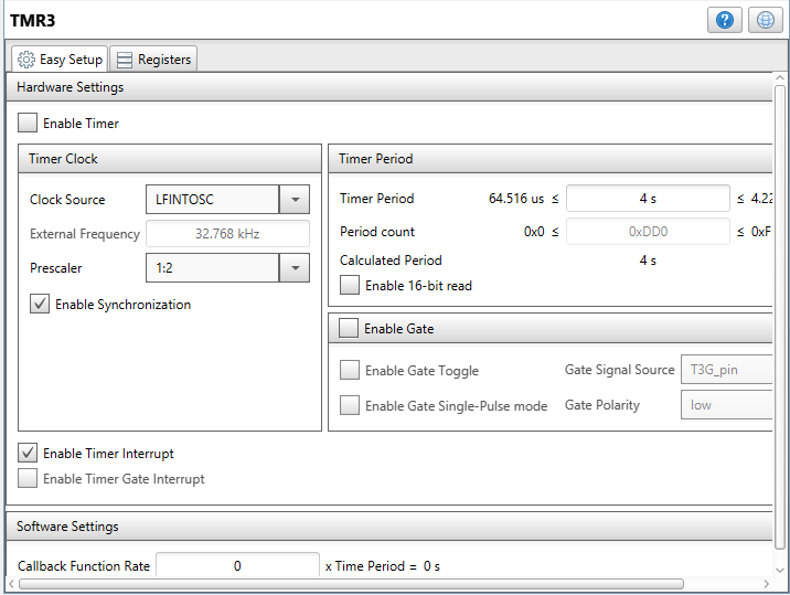
Figure 22: TMR3 settings. (Source: Mouser Electronics)
Putting the Hardware Together
After setting up the software environment, it is time to make hardware connections. The schematic is too wide to show on the webpage, but it can be found on the Mouser Electronics Github page. We used Autodesk EAGLE to develop the schematic. On the Github page, you will find both a PDF and a .sch file.
Important Notes:
- Very important: Make sure to connect Vin- on the LED power supply to GND on the MCU; otherwise, the LED power supply will not recognize the PWM signal from the MCU.
- The schematic will show all physical connections between the capacitive touch and the MCU, but we are really only using the following connections (the rest are left alone, though technically still connected):
|
QT7 Xplained Pro |
PIC18F47K42 Curiosity Nano |
|
PIN4–Y–LINE–1 |
RA2 |
|
PIN6–LED6 |
RD5 |
|
PIN10–Y–LINE–0 |
RD7 |
|
PIN11–LED7 |
RB2 |
|
PIN19–GND |
GND |
|
PIN20–VCC |
VDD |
- To avoid conflicting signals between the capacitive touch and Motion 2 Click (they both share RD7 on the Curiosity Nano), we will bend the EN pin on the Motion 2 Click and solder a wire on it, which will be rerouted and soldered onto pin RD2 on the Curiosity Nano.
Operation
- Power the board with a micro USB cable. Plug in AC adapters connected to the LED bar.
- Open the project file and load it into the MCU.
Figure 23: Set the current time in rtcc5_example.c by changing the highlighted portion; the time is in Unix Epoch Time format.
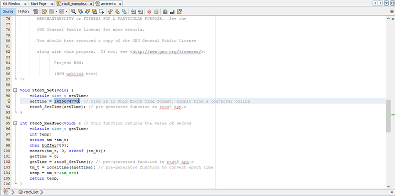
Figure 23: RTC function to set time. (Source: Mouser Electronics)
- If the time programmed into RTC is from 7:00 to 19:00, pressing button 1 will switch between automatic and manual modes. In automatic mode, the color temperature changes each hour based on the time, while in manual mode, pressing button 2 will cycle through different color temperatures, with the initial state switching off the light.
- Figure 24: Adjust the sensitivity of Ambient 7 Click in ambient.c by changing the highlighted portion; it might take a few tries to get it perfect. In addition, Ambient 7 Click will check the surrounding light once every 10 minutes if the time is from 7:00 to 19:00. If it detects that not enough ambient light is present, both cold and warm channels will be switched on at 100 percent duty cycle. By pressing button 1 twice, the system will go back to automatic mode; by pressing button 1 once, the system goes to manual mode. Button 2 is not programmed in this scenario.
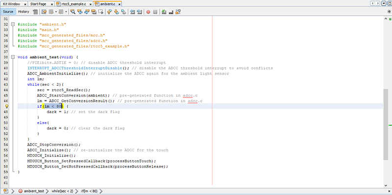
Figure 24: The finished project. (Source: Mouser Electronics)
- If the time programmed into RTC is from 19:00 to 7:00, Ambient 7 Click will be disarmed, while Motion 2 Click will be armed. If motion is detected, both cold and warm channels will be switched on at 100% duty cycle, which can be switched off by pressing Button 2. Button 1 is not programmed during these hours.
Conclusion
Figure 25 shows the completed prototype of the project. The main logic and the hardware connections could have been better crafted, but this project embraces the new era of smart lighting, not only in homes but most importantly, in offices, where most people spend eight hours a day, five days a week. With varying color temperatures based on solar time, this intelligent commercial lighting system sure will help workers stay focused and relaxed at the same time.
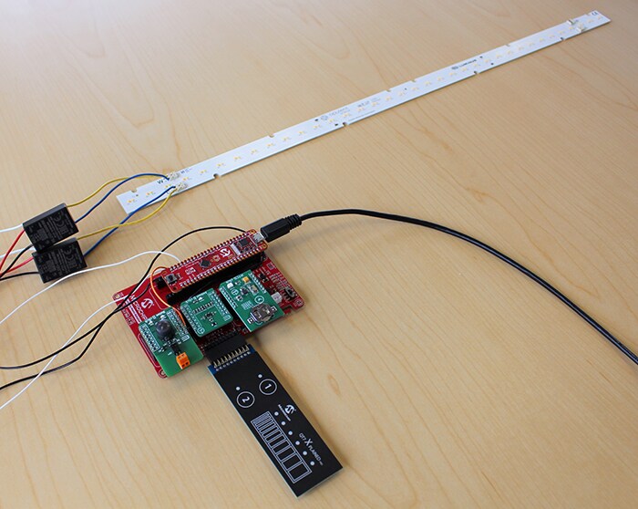
Figure 25: The finished project. (Source: Mouser Electronics)