MOSFET vs. IGBT: Choosing the Correct Switch for Your Power Application
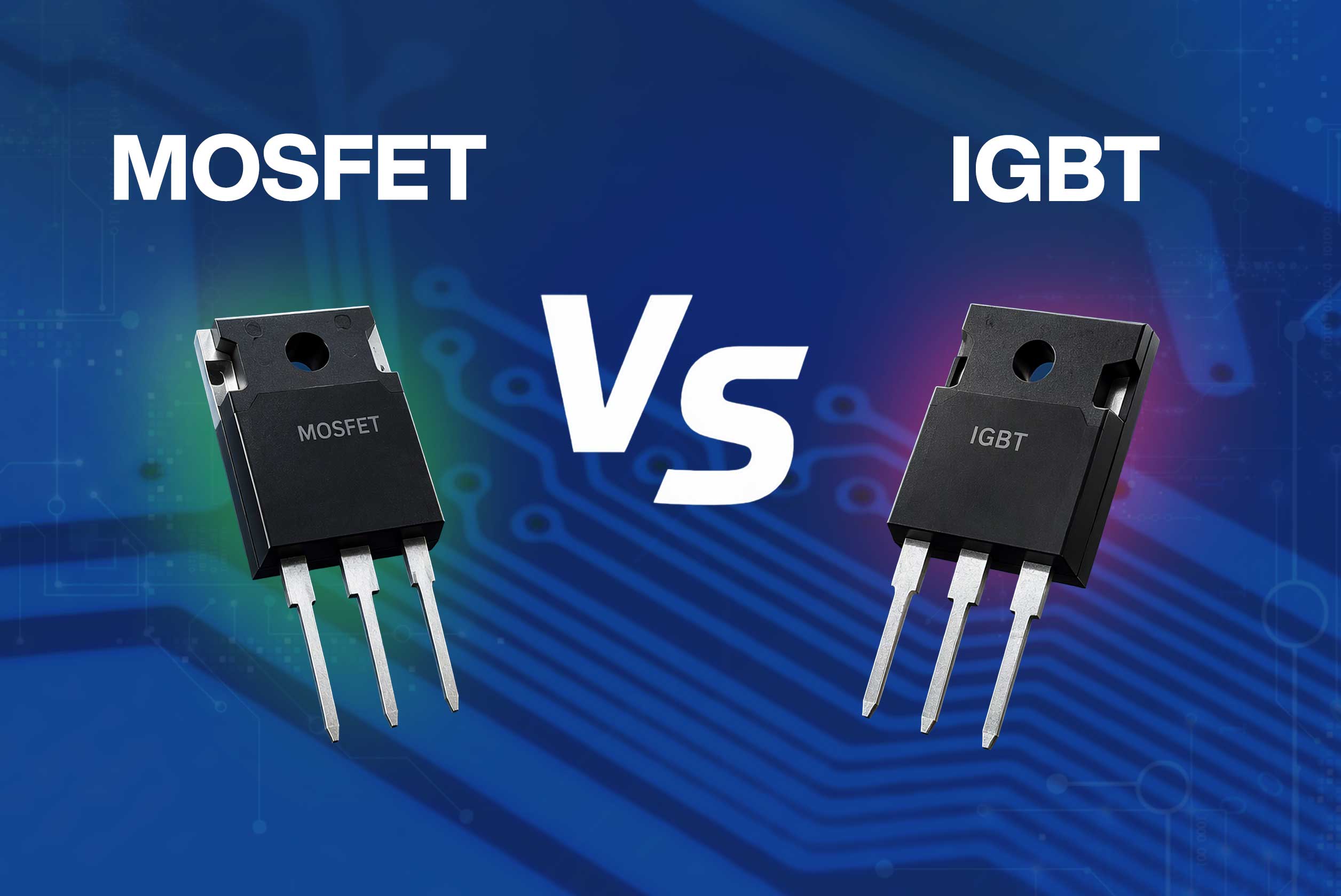
Image Source: Mouser
By Simon Duggleby, Mouser
Published November 20, 2026
Choosing between a metal-oxide-semiconductor field-effect transistor (MOSFET) and an insulated-gate bipolar transistor (IGBT) is one of the most important decisions in power electronics design. The selected switch influences efficiency, power density, thermal performance, system cost, and achievable switching frequency.
Why MOSFET vs. IGBT Switching Matters in Power Electronics
Power semiconductors form the backbone of modern power electronics design. MOSFETs and IGBTs are the two dominant options, each with distinct operating characteristics. Selecting the wrong switching device can result in failure to meet efficiency targets, thermal issues, or development cost overruns in inverters, motor drives, switching power supplies, and power converters. For foundational context, explore MOSFET FAQs: 10 Essential Questions Answered.
MOSFET vs. IGBT Device Characteristics
MOSFETs and IGBTs differ in several important respects:
- MOSFET: A voltage-controlled device that can achieve switching frequencies in the megahertz range. Silicon MOSFETs are deployed in applications ranging from low-voltage systems to systems operating at up to 900V, with devices rated at 1,200V and above available.
- IGBT: A voltage-controlled device that combines a MOSFET input structure with a bipolar transistor output. Designers select IGBTs for their robustness in higher-voltage applications (up to 6,500V) or where switching speeds of 20kHz to 50kHz are acceptable.
For device structural variants, explore Mouser’s Ultimate Guide to Silicon MOSFET Technology.
Voltage Ratings and Breakdown Voltage
While there are devices that support higher voltages, silicon MOSFETs are widely used from low-voltage applications through the 600V to 900V classes. Silicon MOSFETs rated at 1,200V and above are available, although their relatively high on-state resistance can limit their suitability for high-current applications. By comparison, IGBTs operate comfortably from 600V to 6,500V.
The blocking voltage range of 500V to 900V represents an application-dependent crossover region where other factors, such as robustness, thermal considerations, and space requirements, guide designers towards the optimal device.
Conduction Losses
Conduction losses are one aspect to be considered during the selection process:
- MOSFET: Conduction losses are dominated by drain-to-source on-state resistance (RDS(on)). Lower-voltage devices achieve milliohm on-resistance, but this rises sharply with increased voltage rating, penalising applications that handle high continuous currents.
- IGBT: Conduction losses are dominated by collector-emitter saturation voltage (VCE(sat)). Because the voltage drop increases less dramatically with voltage rating than MOSFET RDS(on), IGBTs often provide lower conduction losses in high-voltage, high-current applications.
Switching losses invert this balance. MOSFET switching losses are dominated by capacitive effects from gate charge and output capacitance, scaling linearly with frequency. IGBT switching losses arise from turn-on diode interaction and turn-off tail currents, which dominate total losses at higher frequencies. At low frequencies, IGBTs yield lower total losses; at high frequencies, the MOSFET's switching-loss advantage is decisive.
Body Diodes and Reverse Recovery
Bridge topologies impose strict demands on diode behaviour:
- MOSFET body diode: Incorporates an inherent antiparallel diode formed by the device structure. In bridge circuits, reverse-recovery charge and reverse-recovery time cause shoot-through spikes, switching losses, and electromagnetic interference.
- IGBT: Lacks an inherent body diode, requiring either an external antiparallel freewheeling diode or an integrated co-packed diode whose recovery characteristics dictate switching losses.
Reverse-recovery behaviour directly affects dead-time requirements, switching losses, and electromagnetic interference in half-bridge and full-bridge power converter topologies.
Thermal Performance, Paralleling and Fault Robustness
Operating conditions expose distinct thermal trade-offs:
- Thermal runaway and paralleling: A MOSFET’s room-temperature resistance can double during operation, helping balance current between paralleled devices and reducing the risk of thermal runaway. Conversely, higher temperatures increase IGBT tail currents, reducing switching efficiency. Paralleling IGBTs generally requires greater attention to VCE(sat) matching and current sharing.
- Cooling costs: Thermal management depends on electrical losses and operating conditions. Many high-power systems, regardless of the switch selected, require forced-air or liquid cooling.
- Short-circuit robustness: IGBTs often specify short-circuit withstand times of several microseconds, providing valuable response time for protection circuits. MOSFETs lack such saturation limits, so they require faster protection.
- Derating: Keeping operating temperatures well below the maximum junction-temperature rating preserves long-term reliability.
Quick Comparison of MOSFET vs. IGBT Device Characteristics
Table 1 provides an overview to help engineers apply these selection criteria across diverse topologies.
Table 1. Comparison of MOSFET and IGBT characteristics
|
Characteristic |
Silicon MOSFET |
IGBT |
|---|---|---|
|
Typical Voltage Range |
12V to 950V, with some reaching 1,200V |
600V to 6,500V |
|
Switching Frequency |
Tens of kHz to more than 1MHz |
Typically below 50kHz |
|
Conduction Loss Mechanism |
RDS(on) |
VCE(sat) |
|
Switching Loss Profile |
Switching-transition, gate-charge/output-capacitance, and reverse-recovery losses |
Switching-transition losses, with significant turn-off tail-current loss |
|
Gate Drive Requirements |
Typically +10V to +12V drive |
Typically +15V on, 0V to -5V off |
|
Short-Circuit Robustness |
Generally requires fast protection |
Often specified for short-circuit withstand time |
|
Typical Applications |
Power supplies, motor drives, switching regulators, amplifiers, computing devices, low-voltage automotive electronics |
Industrial motor drives, traction inverters, high-power inverters, welding, UPS, renewable-energy conversion, induction heating |
For common implementation questions, see MOSFET FAQs: 10 Essential Questions Answered.
Choosing a MOSFET or IGBT for Your Power Application
Application-Specific Recommendations
While device-level parameters help narrow the choice, final selection depends heavily on the intended application (Table 2).
Note: The ranges listed in Table 2 are representative. Final device selection requires loss calculations using the intended topology, bus voltage, load current, switching conditions, gate drive, diode behavior, cooling system, and worst-case junction temperature.
Table 2. Comparison of MOSFET and IGBT selection criteria
|
Application |
Voltage Range |
Switching Frequency |
Device Preference |
Selection Factors |
|---|---|---|---|---|
|
Switch-Mode Power Supplies (SMPS) |
12V to 800V |
50kHz to more than 1MHz |
Silicon MOSFETs are strongly preferred, while IGBTs are limited to high-power, lower-frequency designs. |
Designers prioritise low gate charge and switching losses, fast switching speeds, and low RDS(on). |
|
Industrial Motor Drives and Inverters |
230VAC to 690VAC systems |
2kHz to 20kHz |
IGBTs are favoured for high power levels, though silicon MOSFETs remain competitive in lower-voltage, higher-frequency setups such as small servo drives. |
IGBTs remain widely used at higher power levels because of their combination of conduction performance, robustness, and cost at higher voltage/current ratings. |
|
Renewable Energy Inverters and Grid-Tied Applications |
400V to 1500V DC bus |
5kHz to 50kHz |
IGBTs remain widely used in high-power solar and wind converters; silicon MOSFETs are common in lower-power and higher-frequency converters. |
Efficiency, power density, thermal management, switching frequency, and system cost are key selection factors. |
|
Automotive and EV Power Electronics |
12V/48V/400V/800V |
Varies considerably |
Silicon MOSFETs dominate low-voltage functions (12V and 48V systems). IGBTs have traditionally been widely used in high-voltage traction inverters, although SiC MOSFETs are increasingly used. |
Subsystem voltage and operating frequency dictate the choice, with MOSFETs generally preferred wherever high-frequency performance or lower system voltages are required. |
For drive-specific design rules, review the Basics of MOSFETs and IGBTs for Motor Control application analysis.
Emerging Alternatives to MOSFETs and IGBTs
Silicon carbide (SiC) MOSFETs represent a high-voltage, high-frequency alternative that challenges the traditional IGBT domain, offering lower dynamic losses. However, silicon MOSFETs and IGBTs remain the dominant, cost-effective choice for mainstream power conversion today. To evaluate whether next-generation materials change the calculation, review “GaN: Gaining Traction, But Still Short of Fulfilling Its Promise in Power Electronics.”
In summary, low voltage and high switching frequency typically favour MOSFETs, while high voltage, high current, and moderate switching frequencies often favour IGBTs. Selection should always be validated against loss calculations and thermal limits.
Explore Mouser’s comprehensive inventory of power semiconductors to configure your next power stage.