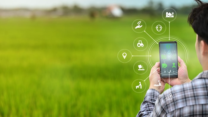
Enabling Smart Agriculture: Building a Better Farm with Microchip and LoRa
By Joseph Downing, Mouser Electronics
Understanding Environment and Soil Quality
Regardless of whether one is growing crops in their backyard or on a large-scale farm, understanding the quality of the environment and the soil is necessary to make informed decisions that affect the quality, nutritional value, and yield of plant-based foods.
Some of the crucial variables that must be monitored include:
Temperature
Extremely high and low temperatures can have adverse effects on the health of plants. High temperatures can cause an imbalance in the photosynthesis and respiration processes that can result in plant suffocation. Conversely, low temperatures can cause plant cells to freeze, which inhibits a plant from getting nutrients.
Humidity
High relative humidity levels prevent a plant from evaporating water as part of its transpiration process. It can also prevent the plant from drawing nutrients from the soil. If these conditions are permitted to continue the plant could rot or suffer bacterial or mold infections.
Moisture Content
The amount of water in the soil must be kept at optimal levels for ideal plant growth. Too much water can result in root rot, which prevents the plant from extracting oxygen from the soil. If there is too little moisture, nutrients cannot circulate through the plant.
pH Level
In chemistry class, we learned the pH scale is a way to indicate the acidity or basicity of a substance. The scale ranges from 0.0 for acids such as battery acid up to 14.0 for bases such as lye. A pH level of 7.0 is considered neutral. Although the ideal pH level can vary from plant to plant, optimum pH levels for soil is between 5.5 and 7.0.
CO2 Level
Plants of all types absorb carbon dioxide (CO2) as part of the photosynthesis process to synthesize food from water (H2O) and CO2. Oxygen (O2), is given off as a byproduct. As with the other factors, too much or too little CO2 can have adverse effects on plant growth and health. As a reference, 250 to 350 parts per million (ppm) is considered a normal concentration in an outdoor ambient environment. Indoor environments with decent air circulation should see a concentration from 350ppm to 1,000ppm.
Project Materials and Resources
This project design uses the Xplained board series from Microchip Technology, which is ideal for rapid prototyping, along with a suite of sensors that will allow the system to monitor the five environmental factors outlined in the previous section. These sensors include the:
- Microchip Technology ATSAMD10-based STEMMA soil moisture sensor
- Bosch BME280 temperature and humidity sensor
- DFRobot SEN0249 soil pH sensor
- DFRobot MG-811 CO2 sensor
Bill of Material (BOM)
Table 1 lists the bill of materials (BOM). Alternatively, you can grab all the parts you need from the preloaded shopping cart at Mouser.com.
Table 1: This plant health monitoring project BOM lists all the components you'll need.
| Quantity | Mouser P/N | Description |
| 1 | 556-ATMEGA328PBXMIN | Development Boards & Kits - AVR ATMEGA328PB Eval Kit |
| 1 | 932-MIKROE-4615 | Mikroe LR 2 Click |
| 1 | 932-MIKROE-1978 | Temperature Sensor Development Tools Weather click |
| 1 | 485-4026 | STEMMA Soil Sensor - I2C Capacitive Moisture Sensor |
| 1 | 426-SEN0249 | Analog Spear Tip pH Sensor / Meter Kit (for Soil and Food Applications) |
| 1 | 426-SEN0219 | Analog IR CO2 Sensor |
| 1 | 854-ZW-MM-20 | Jumper Wires ZipWire MI-MI 20cm 40 UnzippWires x20cm |
| 1 | 932-MIKROE-1097 | PCBs & Breadboards BREADBOARD CLEAR S/A 830 POINTS |
Resources
Computing Resources
- Windows-based computer running MPLAB X IDE
- Wi-Fi® network
- An account on Medium One, available for a fee
- Wi-Fi GitHub® Software Files
- LoRa GitHub Software Files
- AVR® and Arm® Toolchains (C Compilers)
- Microchip ATmega Series Device Support (2.0.12)
Software Files
The Microchip Technology Xplained board is programmable using MPLAB X IDE. In addition to the prebuilt libraries that the parts vendors provide, the project will require additional files already included in the main project file. The first is the firmware file that runs on the Microchip Technology Xplained board. AA header (.h) file to store any sensitive data such as passwords and application programming interface (API) keys (which are things one should avoid sharing with the entire world on GitHub), is in the ArduinoCore/Include folder. Lastly, an included library project (ArduinoCore) should be attached to the main project file that will include everything necessary for each of the devices. The original project file was created utilizing Atmel Studio 7 and was imported into MPLAB X IDE. To build this program, you will need to incorporate the AVR toolchain as well as a device support pack, both linked above. The primary project file can be found in the SmartAgFirmware folder.
Tools and Other Resources
Finally, these tools are recommended to help complete the project:
- Wire strippers
- Digital multimeter
- Needle nose pliers
- Breadboard
- Pull-up resistors if needed for I2C bus
Project Technology Overview
Sensor boards used in this project communicate back to the Xplained microcontroller board in two ways: By digitally utilizing the Inter-Integrated Circuit (I2C) serial communication protocol or via an analog signal that is read by the microcontroller’s analog-to-digital converter (ADC).
STEMMA Soil Moisture Sensor
The STEMMA Soil Moisture Sensor communicates via I2C. The sensor measures the capacitive difference between the two probes and reports and has an integer value from 300 to 500 based on the moisture content of the soil.
BME280 Temperature Sensor
The BME280 Temperature Sensor communicates via I2C. It reports a floating-point number with a unit of measure of degrees Celsius. The value is convertible to degrees Fahrenheit using the formula:
F = Cx 9/5 + 32
BME280 Humidity Sensor
The BME280 Humidity Sensor communicates via I2C. It reports a floating-point number with a unit of measure in the percentage of relative humidity.
SEN0249 Soil pH Sensor
The output of the SEN0249 Soil pH Sensor is an analog signal from 0 to 5VDC. The pH is a unitless measure that will range from 0 to 14. The formulas to calculate the pH level are:
Voltage = ADCx (5V/1,024)
where ADC is the value read by the microcontroller’s ADC pin connected to the pH sensor.
The formula assumes the microcontroller has a 5V operating voltage and 10-bit ADC. These numbers may require an adjustment if you use an alternative microcontroller with a different operating voltage and/or ADC resolution. Then calculate the pH level:
pH Value = (3.5x Voltage) + Offset
The offset is a variable that is determined during the calibration process for the pH sensor. Note that this sensor must be recalibrated every two hours. Find more information on the calibration process on the DFRobot site.
MG-811 CO2 Sensor
The output of the MG-811 CO2 Sensor is an analog signal from 0 to 5VDC. The unit of measure is the concentration of CO2 ppm. The following formulas are used to translate the analog voltage value to a CO2 concentration in ppm:
Voltage = ADCx (5V/1,024)
where ADC is the value read by the microcontroller's ADC pin connected to the MG-811 CO2 sensor.
The formula assumes the microcontroller has a 5V operating voltage and 10-bit ADC. These numbers might require an adjustment if you use an alternative microcontroller with a different operating voltage and/or ADC resolution. If the calculated voltage is less than 0.4V, then the sensor has not yet warmed up enough and no readings should occur at that time. Once the voltage rises above 0.4V, the following formula can be useful to make the final CO2 concentration calculation:
CO2 Concentration (ppm) = [(Voltage − 0.4) x 5000]/1.6
Building the Electronics
Assembling this project is straightforward. A small breadboard is useful, as there are two devices that require access to the I²C serial communications bus. The nice thing about development boards is they come with the required pull-up resistors for the I²C bus to work. However, when making a custom printed circuit board (PCB) integrating these devices, remember the resistors on the serial data line (SDA) and serial clock line (SCL) wires. For more tips on I2C customizations check out Mouser’s Chip To Chip: Tips For Using I2C Bench Talk blog.
STEMMA Soil Moisture Sensor
- Plug the 4-wire JST cable assembly into the JST connector on the signal transmitter board.
- Connect the Vin (red wire) pin of the sensor to the 3.3V rail of the breadboard.
- Connect the GND> (black wire) pin of the sensor to the ground (GND) rail of the breadboard.
- Connect the SDA (white wire) pin of the sensor to the SDA pin of the Xplained board.
- Connect the SCL (green wire) pin of the sensor to the SCL pin of the Xplained board.
Mikro Weather Click BME280 Temperature and Humidity Sensor
- Solder a set of female headers to the Mikro Weather click sensor board.
- Place a wire from the 3.3V pin to the 3.3V rail of the breadboard.
- Place a wire from the GND pin to the GND rail of the breadboard.
- Connect the SDA pin of the sensor to the SDA pin of the Xplained board.
- Connect the SCL pin of the sensor to the SCL pin of the Xplained board.
SEN0249 Soil pH Sensor
- Plug the 3-wire JST cable assembly into the JST connector on the signal transmitter board.
- Connect the GND (black wire) pin of the signal transmitter board to the GND rail of the breadboard.
- Connect the +V (red wire) pin of the signal transmitter board to the 5V rail of the breadboard.
- Connect the analog output (blue wire) pin of the signal transmitter board to the A0 pin of the Xplained board.
Analog Infrared CO2 Sensor
- Plug the 3-wire JST cable assembly into the JST connector on the signal transmitter board.
- Connect the GND (black wire) pin of the signal transmitter board to the GND rail of the breadboard.
- Connect the +V (red wire) pin of the signal transmitter board to the 5V rail of the breadboard.
- Connect the analog output (blue wire) pin of the signal transmitter board to the A1 pin of the Xplained board.
LoRa 2 RF Development Click Board
- Place a wire from the 3v3V pin of the LoRa board to the 3.3V rail on the breadboard
- Place a wire from the GND pin of the LoRa board to the GND rail of the breadboard
- Place a wire from the TX pin of the LoRa board to pin PD2 of the Xplained board
- Place a wire from the RX pin of the LoRa board to pin PD3 of the Xplained board
- Place a wire from the RST pin of the LoRa board to pin PB0 of the Xplained board
Microchip Xplained Board
- Place a wire from the 5V pin to the 5V rail of the breadboard.
- Place a wire from the 3.3V pin to the 3.3V rail of the breadboard
- Place a wire from the GND pin to the GND rail of the breadboard.
- Insert the micro USB cable into the micro USB port of the Xplained board.
- Insert the other end USB cable (Type-A port) into the USB port of a computer.
Software and Programming
In this section, details for the software side of the project are provided. This will include the firmware and support files essential for the Microchip Xplained board.
Setting up the Microchip Xplained Board Firmware
Project Files
Table 2 identifies the Microchip Xplained project files in this project’s GitHub repository:
| File Name | Contents |
sketch.cpp |
The project-specific code for this effort is stored in this file. It is based upon an example Medium One provides to demonstrate how embedded devices can interact with the Internet of Things (IoT) platform backend. |
secretstuff.h |
When working on a project that is made publicly available, there is always a risk of exposing sensitive data like passwords or API keys. Instead of hardcoding such information directly into the firmware and having to remember to alter the code prior to each "git commit," we can instead create an unpublished header file to store this information. Note that we have provided an example of the header file in the GitHub repository. The example is named mysecretstuff.h. Be sure to rename the file to secretstuff.h before attempting to compile the code on your computer. |
co2_sensor.h |
This is a custom header file written for interacting with the CO2 sensor. A header file is where the functions and variables are declared. The #include preprocessor directive is used to include this library in the main sketch.cpp file. |
co2_sensor.cpp |
The source code used to interact with the CO2 sensor is found in this file. |
Libraries
The preprocessor directive #include lets us add libraries into our projects. This promotes code reuse; unless you have very specific needs, reinventing the wheel is not necessary. This project uses the following libraries:
<RN2xx3.h>:This library enables communication with a LoRa (Long Range) network on a sub-gigahertz frequency utilizing the RX/TX lines for communication. This library will work for either the RN2903 or RN2483.<Wire.h>:Thewire.hlibrary provides foundational code necessary to interact with the I2C hardware. The BME280 temperature/humidity sensor and the soil moisture sensor occur over the I2C serial communications protocol. Component-specific libraries will build upon this library to provide functionality for their respective parts.<Adafruit_Sensor.h>and<Adafruit_BME280.h>:These libraries provide support functions essential to interact with the temperature/humidity sensor. These libraries are available for download here.<Adafruit_seesaw.h>:This library provides functions to interact with the STEMMA soil moisture sensor. The library can be found here."SoftwareSerial.h":TheSoftwareSerial.hlibrary allows for a software-based serial communication channel on any two general-purpose input/output (GPIO) pins (RXandTX). Although not as fast as the hardware serial port, it does allow for separate serial channels for debugging and interacting with a Wi-Fi chipset."secretstuff.h":This header file contains sensitive information such as Wi-Fi passwords and the Medium One passwords and API keys. Notice that this header file is encapsulated by quotation marks and not < and > that the other header files utilize. This is because thesecretstuff.hheader file resides in the project-specific firmware folder and not in the header files library that all projects can use. This file location makes this header file only accessible to the project’s firmware.
Variables and Constants
These are variables one might want to tweak to accommodate your specific design choices:
static int heartbeat_timer = 0:A timer to ensure communication connectivity between the microcontroller and the Medium One sandbox dashboard even if a sensor fails.static int sensor_timer = 0:A timer to track the length of time since the last packet of sensor telemetry was sent to the Medium One dashboard.static int heartbeat_period = 60000:The amount of time, in microseconds, between heartbeat signals sent to the Medium One dashboard.long lastReconnectAttempt = 0:The storage location of the timer value of when the last connection was made.static int sensor_period = 5000:The interval between taking readings from the sensors.const float vref = 5.0:The operating voltage of the microcontroller, which is an essential verification for analog-to-digital conversion calculations. This voltage might require an adjustment with the use of a 3.3V operating voltage microcontroller.const float phOffset = 0.0:The offset added to the pH calculation formula. This value is determined during the calibration process of the pH sensor.const int phSensorPin = A0:The analog input (A0) pin to which the pH sensor connects.const int co2SensorPin = A1:The analog input (A1) pin to which the CO2 sensor connects.
A quick note on the const and the static keywords:
Placing the const keyword in front of the variable type ensures that value will not change during execution. In effect, creating a constant instead of a variable. The advantage of const versus #define is that since the variable is declared with a type, the compiler ensures that the variable type is respected throughout the code.
The static keyword ensures that the value stored in the variable remains the same (unless specifically changed by the code), even as a functions call goes out of scope. When the function is called again later, the value that was held previously in the static variable will still be there, versus declaring and initiating the variable as if it was the first time the function was called.
Objects
SoftwareSerial soft(2, 3):This creates a software-defined serial port with microcontroller2pin serving as the RX pin and microcontroller3pin serving as theTXpin.Adafruit_BME280 bme:This creates an object to interact with the temperature and humidity sensor.Adafruit_seesaw soilSensor:This creates an object to interact with the STEMMA soil moisture sensor.co2_sensor co2sensor:This creates an object to interact with the CO2 sensor.
Functions
void setup():This first function to run will initialize many of the hardware and software components required such as the serial communications, Wi-Fi connection, sensor interface, and interactions with theGPIOpins.void loop():This is the core of the functionality that will run continuously. Care is taken to ensure the main loop has minimal code and that functionality is handed off to specialized functions that are each responsible for individual tasks needed to make this project work.void sensor_loop():This function handles polling the BME280 environmental sensor for temperature and pressure data and transmits it to the Medium One sandbox dashboard.float getPHlevel():This function requests the pH level from the pH sensor. A floating-point number (from 0.0 to 14.0) is returned.void heartbeat_loop():This loop provides a heartbeat to the Medium One server. A heartbeat is a consistently repeating packet that lets the server know that our device is still alive and able to communicate even if there is no data to pass. This is very useful for applications that only transmit data once an event occurs in the real world.
Getting Started with Your Project
Before getting started, take time to do some testing and calibrating, and then start monitoring your horticulture project!
Check for Errors
Hook up the Xplained board to a computer and fire up a serial terminal. Telemetry from the various sensors should be flowing down the screen every few seconds. If not, check for any error messages. Some common errors include:
- Reversing power and ground wires to sensors.
- Reversing the data (
SDA) and clock (SCL) wires to the sensors. - Not wiring the
TX/RXpins correctly between the Xplained microcontroller board and the LoRa 2 Click Board. TheTXpin from one board should connect to theRXpin on the other board. - If powering the device, not ensuring the power supply can deliver at least 1A of current.
Calibrate the Sensors
Calibrating the sensors is essential. Despite the best intentions of manufacturers, no two sensors that come off the assembly line are quite the same, thus the need for the calibration process. One common method employs a potentiometer that can adjust the output signal to a prescribed voltage or current when a specific input signal is injected. Typically, the potentiometer influences the negative feedback loop of an operational amplifier, which is typical for a sensor device.
Calibration is not a one-time, upfront activity. Many sensors are affected by a phenomenon known as sensor drift. Over time, the operating environment or operating conditions can begin to affect the circuit and the output signal so much so that the same inputs will generate a different output over time. Left unchecked, the drift will become increasingly worse. Therefore, it’s crucial to remember that some devices, such as those used in industrial, agricultural, and horticultural applications, might have an expected service life that’s measured in decades. Ensuring that calibration occurs in line with the manufacturer’s prescribed manner and timeline is vital for safe and reliable system operations.
Connecting to the Cloud
Now that you have the sensors streaming data, you need to find a way to get this up to the cloud. A number of options exist that can be found by simply searching on Google. One option could be to use a LoRa-Enabled Gateway such as RG-191 from Laird Connectivity. The Quick Start Guide will help you connect to The Things Network (TTN), register your device, and begin sending data. You can also find additional resources on LoRaSever.io on how to create your own.
Conclusion
Whether you’re a seasoned gardener or just starting out, this project can provide you the means to create an ideal and efficient environment to cultivate plants for consumption or transplant. The sensors and IoT capabilities can help you monitor and makes changes as needed to help anyone have a green thumb.
Don’t forget to let us know if you tried this project out for yourself. How well did the project work for you? What else could you do to expand upon it? If so, let us know on Facebook, Twitter, LinkedIn, or Instagram.