Unlocking Precision
Bluetooth-Based Indoor Positioning Technology

Image Source: photographicss/Stock.adobe.com
By Joseph Downing for Mouser Electronics
Published October 3, 2023
Bluetooth® indoor positioning is an innovative technology that is revolutionizing the way we navigate and interact within indoor spaces. This innovative technology is reshaping the landscape of location-based services. With its ability to provide precise and reliable positioning information in indoor environments, Bluetooth indoor positioning offers numerous applications, from enhancing indoor navigation for consumers to enabling asset tracking to proximity-based experiences for businesses.
At the core of Bluetooth indoor positioning is the use of Bluetooth Low Energy technology, which allows devices to exchange data efficiently while conserving power. By leveraging Bluetooth Low Energy beacons strategically placed within indoor spaces, this technology enables smartphones, tablets, and other compatible devices to determine their precise locations with a high degree of accuracy. Consumers can enjoy seamless navigation within complex buildings like shopping malls, airports, and museums, while businesses can optimize their operations with real-time asset tracking and personalized location-based services.
This article will provide the reader with the necessary steps to use the u-blox XPLR-AOA-2 Explorer Kit to demonstrate the functionality of Bluetooth indoor positioning, including programming, setup, and placement.
Project Material and Resources
Project Bill of Materials (BOM)
Project Code/Software
- Local Positioning Engine 2.0.X
- u-connectLocate
- nrfutil Flashing Tool
- C209 AoA Tag Software Release
- s-center Wi-Fi® and Bluetooth evaluation software
Additional Resources
- User guide for u-blox XPLR-AOA-1 and XPLR-AOA-2 Explorer Kits
- Bluetooth indoor positioning user guide
Additional Hardware
- USB (A) to USB Micro (B) cable assembly × 4
- Phillips-head screwdriver
- u-blox EVK-ODIN-W2 Evaluation Kits (Optional)
Project Technology Overview
This is an intermediate-level project, though it could become more difficult if you attempt to use the wireless option outlined in the u-blox Explorer Kits user guide. This design of this project highlights the following products.
u-blox XPLR-AOA-2 Explorer Kit
The u-blox XPLR-AOA-2 Explorer Kit is specifically designed for assessing and experimenting with Bluetooth 5.1 direction-finding technology, intended for indoor positioning use cases. This kit includes four C211 antenna boards, each equipped with a u-blox NINA-B411 module, as well as four C209 tags, each featuring a u-blox NINA-B406 module (Figure 1).
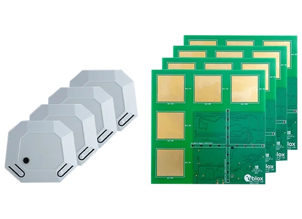
Figure 1: u-blox XPLR-AOA-2 Explorer Kit. (Source: Mouser Electronics)
By combining the antenna boards (C211) and tags (C209) with the necessary software, the XPLR-AOA-2 Explorer Kit facilitates the evaluation of Angle-of-Arrival (AoA) technology, enabling highly precise indoor positioning. The AoA technology is utilized by antenna points that contain an antenna array connected to a Bluetooth receiver. Through this technology, the kit can determine the direction or angle of a moving tag, which transmits a signal with an appended Constant Tone Extension (CTE).
The kit performs its calculations using the u-connectLocate software, which operates on the embedded MCU in the NINA-B411 module. By leveraging the direction-finding capability alongside the robust Bluetooth communication link and low current consumption, this kit empowers the construction of exceptionally accurate indoor positioning systems. These systems can calculate the position of the tag by triangulating the directions received from three or more antenna points.
NINA-B411 Module on the C211 Antenna Boards
The u-blox NINA-B41 Series Bluetooth 5.1 Low Energy modules are built around the Nordic Semiconductor nRF52833 chip and offer pin compatibility with the NINA-B3 module. This series includes the NINA-B416 (Figure 2), NINA-B411, and NINA-B410 modules.
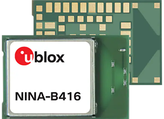
Figure 2: u-blox NINA-B416 Bluetooth 5.1 Low Energy module. (Source: Mouser Electronics)
The NINA-B416 module comes with a built-in integrated antenna, which streamlines the integration process by eliminating the necessity for an RF trace design on the host PCB. The NINA-B411 module foregoes the integrated antenna for an output pin to connect to an external antenna, while the NINA-B410 features a U.FL connector that facilitates the connection of an external antenna to the module.
NINA-B406 Module on the C209 Tags
The u-blox NINA-B40 Series stand-alone Bluetooth Low Energy modules (Figure 3) are compact devices designed to excel in demanding professional environments. Boasting Bluetooth 5.1 capability, these modules also offer support for NFC and IEEE 802.15.4 with Thread and Zigbee, making them versatile enough for a variety of applications.
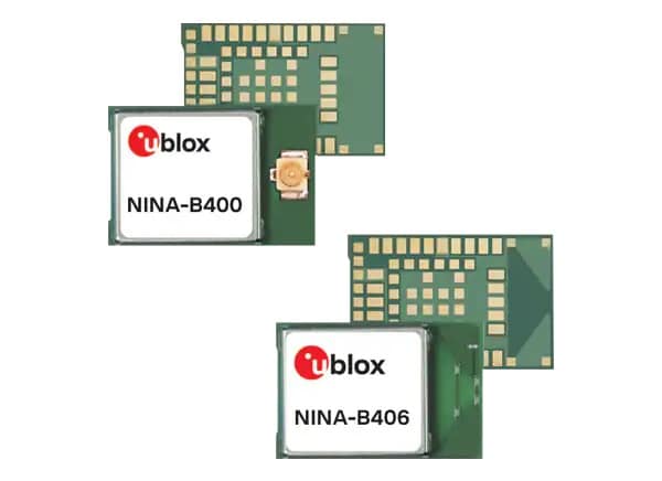
Figure 3: u-blox NINA-B40 Series stand-alone Bluetooth Low Energy modules. (Source: Mouser Electronics)
The NINA-B406 version is equipped with an internal PCB antenna, providing a sturdy, low-profile solution with exceptional performance and extended range. Conversely, the NINA-B400 variant comes with a U.FL connector, allowing for seamless integration with an external antenna of choice. Moreover, these modules have been globally certified for use with either the internal antenna or a variety of external antennas, effectively reducing integration time, cost, and effort for incorporating Bluetooth low energy into designs.
With support for UART, SPI, PDM and PWM, I²C, I²S, GPIO pins, and AD converters interfaces, the NINA-B40 Bluetooth Low Energy modules offer versatile connectivity options. This enables their application in indoor positioning, wayfinding, and asset tracking, among other use cases.
Developing the Project
The XPLR-AOA-2 Explorer Kit comes with almost everything you’ll need to set up the demonstration outlined in this project. A wireless configuration is also available; however, this project will use strictly a USB-to-serial interface to relay the information from the four antenna boards. Along with the addition of the CR2032 coin cell batteries, this project uses four 4.88m (16ft) USB(A)-to-micro-USB(B) cables to provide enough length to create a suitable area to show each of the four tags positions effectively. Additionally, this demonstration uses a PC running Windows 10.
Software Setup
The four tags and four antennas all come loaded only with a bootloader, and each will need to be programmed before they can be setup and configured for the demo. It is recommended that the tags are programmed before the coin cell batteries are installed.
C211 Antenna Programming
Starting with the antenna boards:
- Download the u-connectLocate software linked in the Project Code/Software
- Locate and extract the downloaded .zip file, remembering the location.
- Use one of the four USB cables and plug the antenna (J8) board being programmed into the PC.
- Using the Windows search bar, type Device Manager and press return.
- Locate and open Ports (COM & LPT), and then identify the COM port used by the antenna board. (Note the port number, as each antenna board will have a unique COM port assigned; see Figure 4.)
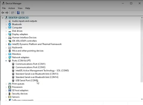
Figure 4: Device Manager window showing Ports (COM & LPT). (Source: Mouser Electronics)
- In the Windows search bar, type CMD and press enter to open the Command Prompt.
- In the Command Prompt window (Figure 5), type the following command line: newtmgr –conntype=serial –connstring=”COMXX,baud=115200” image upload <binary file>
- Replace the XX next to COM with the port listed in the Device Manger for the specific antenna board being programmed.
- Replace <binary file> with the .bin file located in the extracted u-connectLocate.zip file.
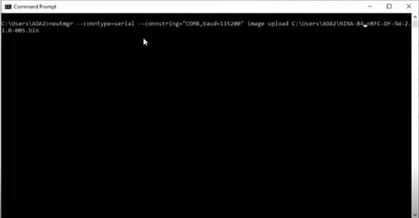
Figure 5: CMD Window with command line for programming C211. (Source: Mouser Electronics)
- Once the programming is complete, press the Reset button on the board. If programmed correctly, the LED at DS1 should light green (Figure 6).
- Repeat steps 3 through 8 for each antenna board.
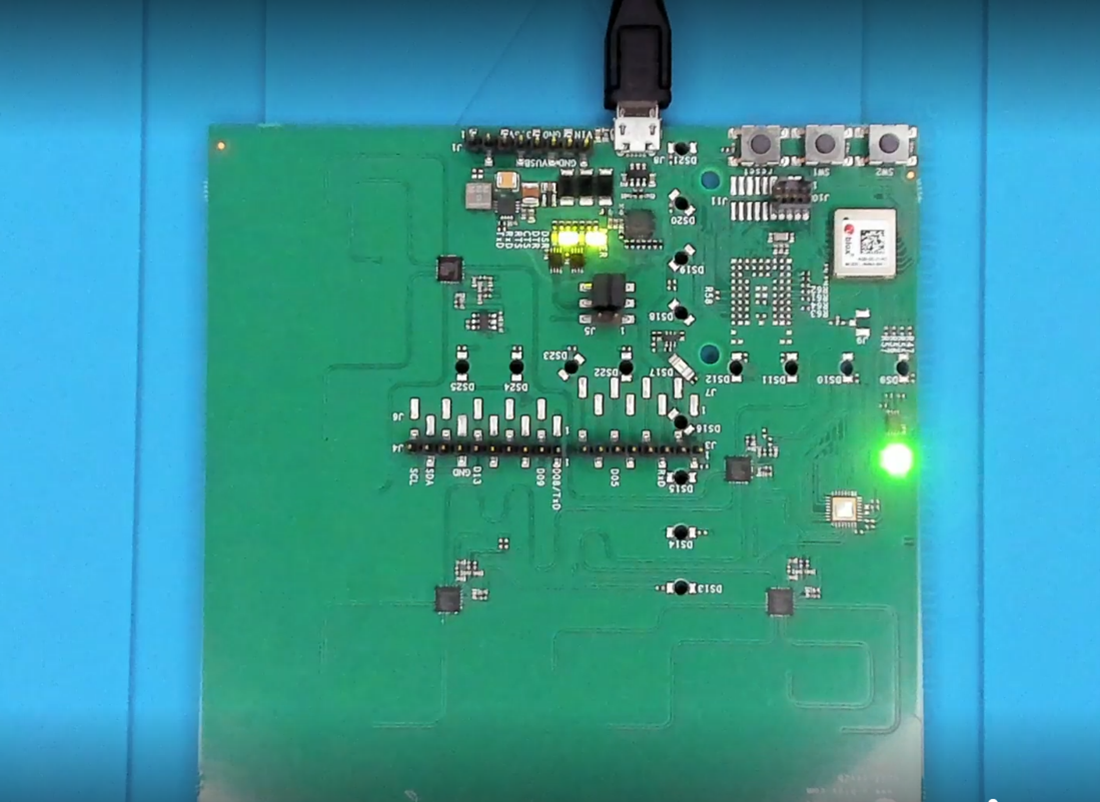
Figure 6: Illuminated LEDs on C211 after programming. (Source: Mouser Electronics)
C209 Tags
The C209 tags will require two software downloads to program them.
- Download and install the nrfutil flashing tool from the Nordic GitHub Repository using the nrfutil Flashing Tool link in the Project Code/Software
- Download and extract the C209 tag software release from the Project Code/Software
- The extracted files will contain the “app”.zip file used for the installation.
- Press and hold SW2 on the C209 tag board while inserting the USB programming cable into J1 on the C209. (This will set the bootloader into “download” mode.)
- Using Device Manager, identify the COM port assigned to the C209 tag. (Like the antenna boards, each of the C209 tags will have a unique COM port assigned.)
- In the CMD window, type in the following command line: nrfutil dfu serial -pkg “app”.zip -p COMXX -b 115200 -fc 1
- Replace “app” with the name of the .zip file contained within the extracted C209 tag software release (for example, NINA-B4-DF-TAG-SW-2.0.1-001.zip)
- Replace the XX following COM with the appropriate port number.
- Once programming is complete, unplug the USB cable from the C209 tag.
- Once powered, a steady blinking blue LED should become active.
Local Positioning Engine
The Local Positioning Engine provides the user the means to set each antenna board’s position as well as to visualize each tag within the defined space.
- Using the link provided in the Project Code/Software, navigate to the Local Positioning Engine 2.0.x and download the file.
- Locate the downloaded file and extract the contents.
- Open the new folder and locate server.exe and execute the file.
To access the engine, open a web browser window and navigate to http://localhost:5000/
From here you can upload your own floor plan or using a preexisting one, set the overall dimensions of the room as well as the locations and position of each antenna board. (These steps will be covered later in the article.)
Hardware Setup
Though hardware setup for this kit is straightforward, you may find it difficult to mount each of the antenna boards in place. Additionally, you will need to ensure that the PC running the Local Positioning Engine contains the number of USB ports required to connect to all four antenna boards simultaneously.
- Insert the coin cell batteries into the open battery holders on the back of each C209 tag.
- Reassemble each tag inside the casing using the two Phillips-head screws removed during disassembly.
- Plug four USB(A) to micro-USB(B) cables into four available USB ports on the PC running the Local Positioning Engine server.
- Plug the other end of the USB cable into each of the antenna boards. Once the boards are connected, their green LEDs should light.
Using a bit of ingenuity, measure and mount each of the antenna boards as shown in Figure 7.
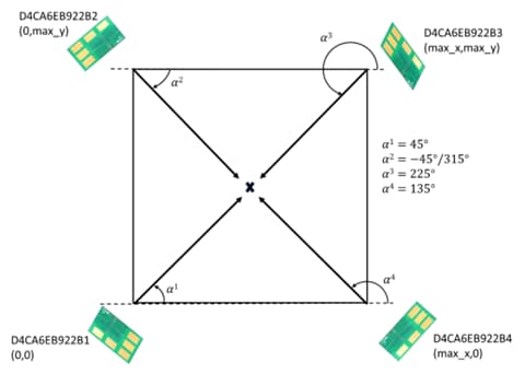
Figure 7: C211 antenna board placement configuration. (Source: u-blox)
Putting It All Together
With everything programmed, the tags reassembled, and the antenna boards mounted, it’s time to configure the area being monitored. In the Local Positioning Engine, the menu offers several options; but for this demonstration will use only Floorplan, Antennas, and Map View.
- Select Floorplan from the menu at the top of the u-blox Pos Server (Figure 8).
- Set the measurements of the area covered by the antenna boards.
- Select “Upload new floorplan.”
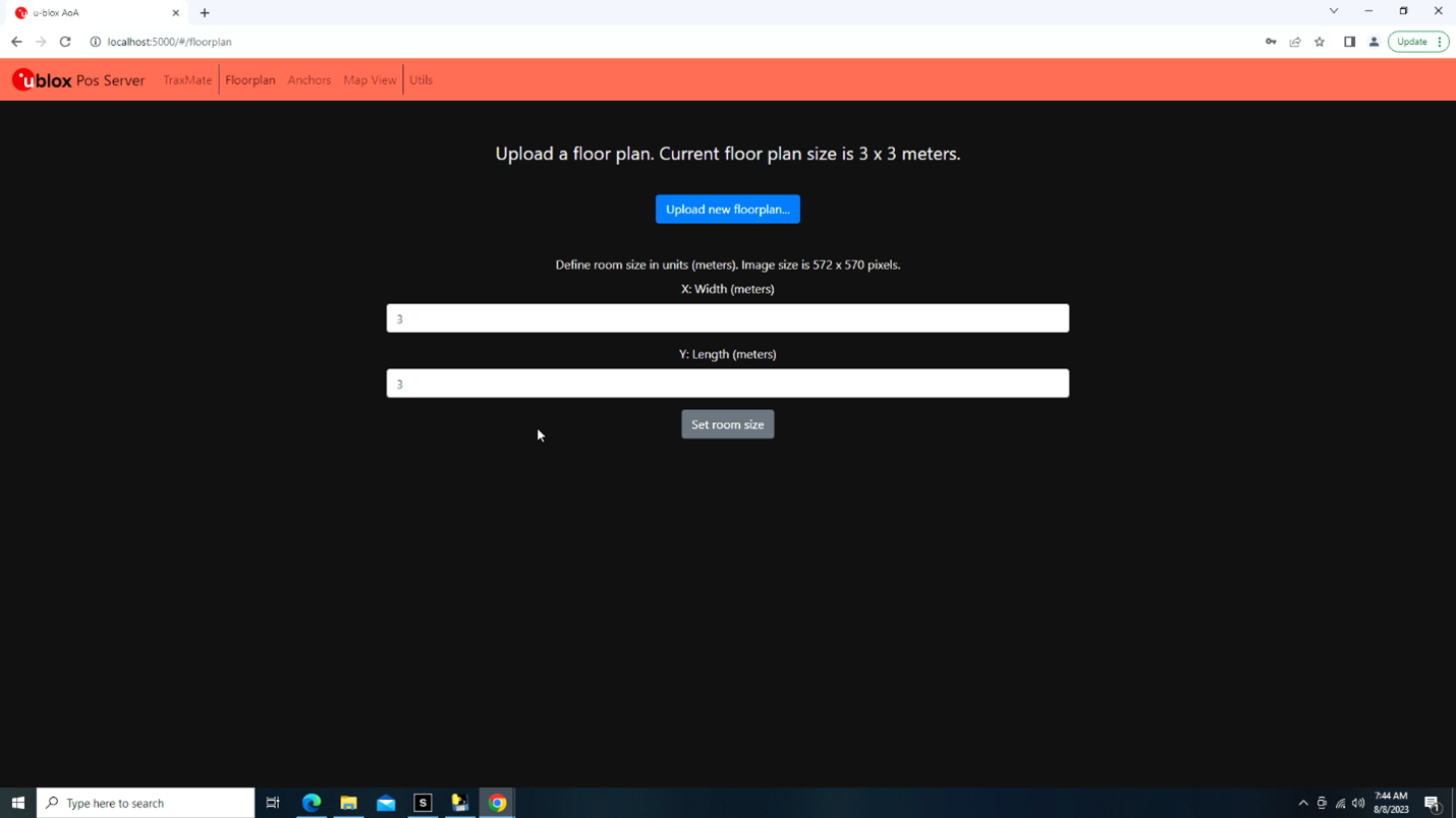
Figure 8: u-blox Pos Server floorplan. (Source: Mouser Electronics)
- Note: From here you have a choice of uploading your own floor plan (the floor plan should be in png, jpg, jpeg, tiff, tif, bmp, gif, or ppm format) or using one of the pre-defined plans provided in the same file as the Local Position Engine server program (Figure 9).
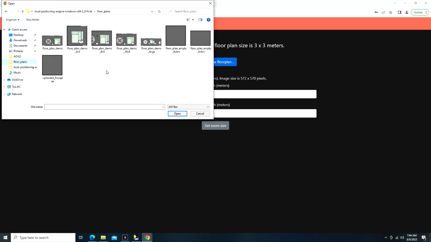
Figure 9: u-blox Pos Server generic floorplans. (Source: Mouser Electronics)
- Select “Anchors” from the top menu (Figure 10; you may receive a pop-up message regarding unconfigured boards).
- Select the board to be configured using the drop-down menu just below the menu bar.
- Using the instructions provided regarding setting of positions for the X, Y, Z axes, set the variables as necessary to match the area the antennas will monitor.
- Next, you will need to set the azimuth, which will determine the angle the boards are directed in the mounted position.
- Once set, select “Configure antenna” to complete.
- Repeat steps 1 through 8 for each of the three remaining antenna boards.
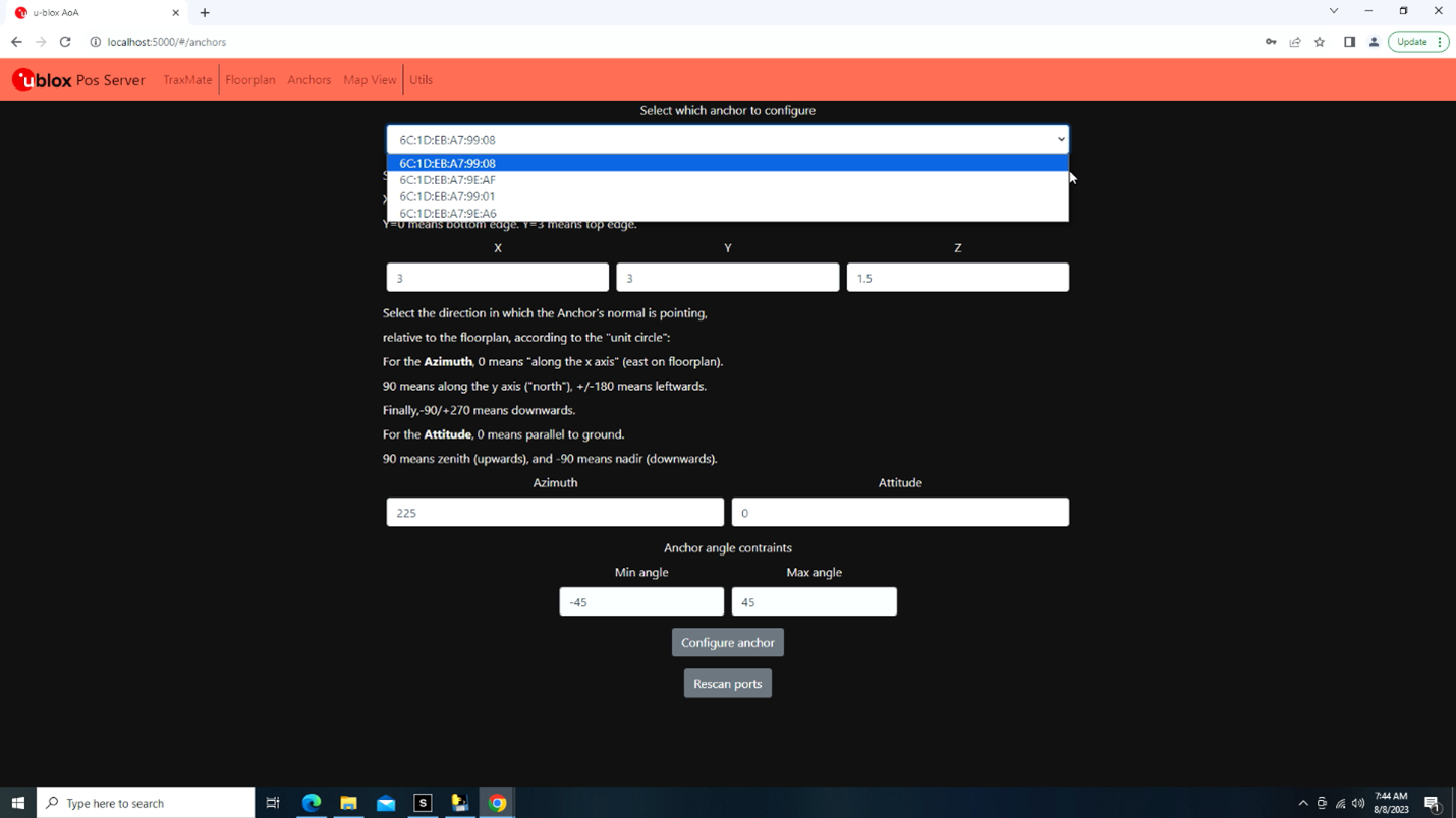
Figure 10: u-blox Pos Server anchor configuration. (Source: Mouser Electronics)
Once you’ve completed configuring the layout of the antenna boards within the space, you can now view the space, adjust, and begin monitoring the tags.
- Select “Map View” from the top menu.
- View each of the antenna points to verify placement and azimuth is set correctly.
- Select the Play icon in the lower-left corner of the screen.
Dots representing each of the tags should appear, showing the tags' positions within the space (Figure 11).
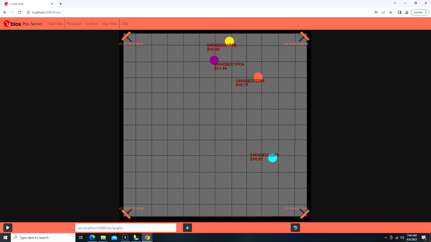
Figure 11: u-blox Pos Server showing all four tags. (Source: Mouser Electronics)
Taking It a Step Further
Because this project was completed using a USB-to-serial interface, it can be limiting when attempting to configure a large space. The linked guides do provide a wireless variation that requires additional hardware but opens the possibilities by increasing the size of the space that can be monitored. Along with the TraxMate option in the Local Position Engine, you can not only increase the overall area, but also use your own physical location on a map to provide the floorplan (Figure 12).
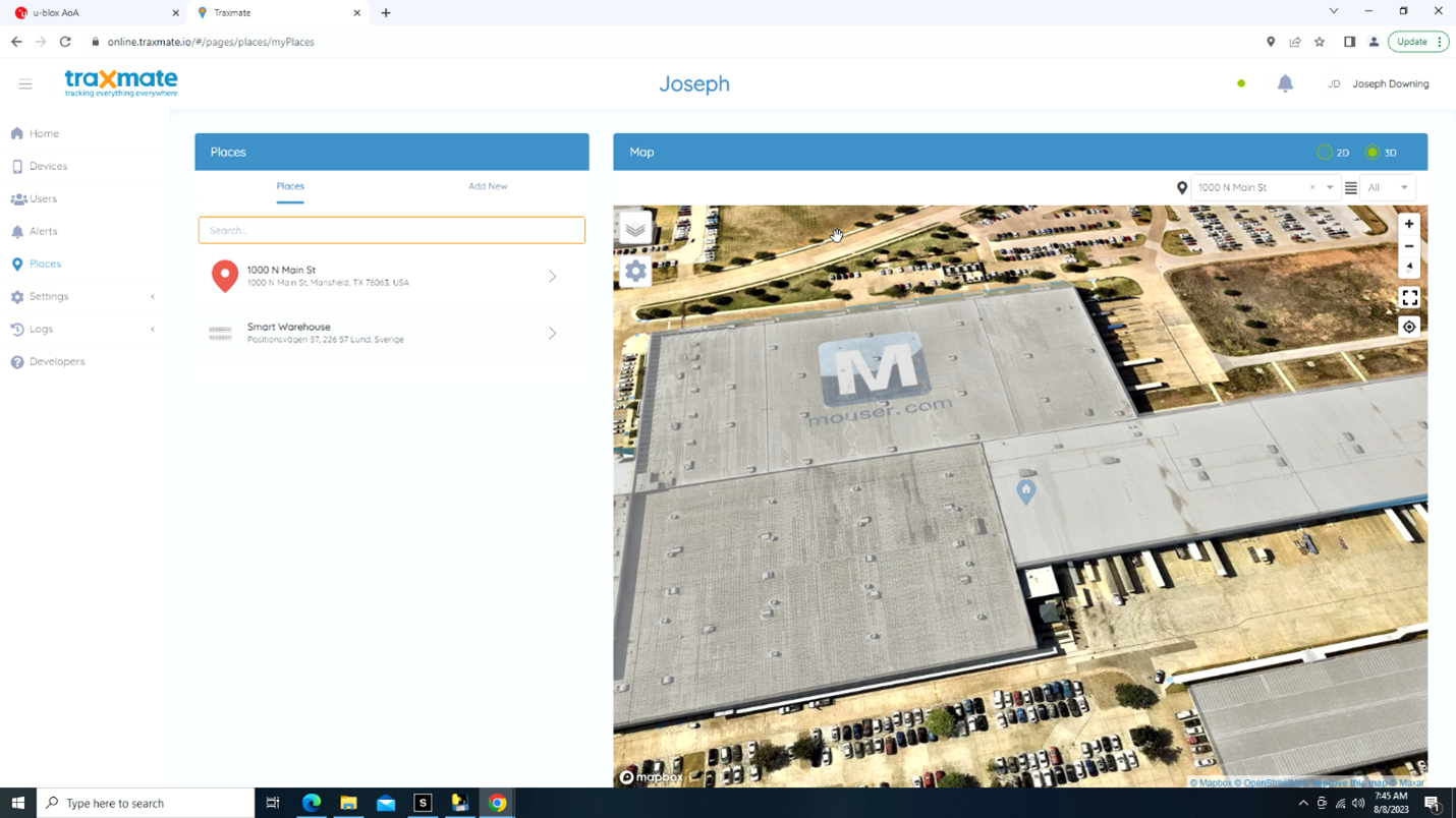
Figure 12: Traxmate location configuration. (Source: Mouser Electronics)
Conclusion
Bluetooth indoor positioning is transforming the way we navigate and interact within indoor spaces. With its precise and reliable positioning capabilities, this innovation is reshaping the landscape of location-based services, opening numerous possibilities for enhancing consumer experiences and optimizing business operations.
At its core, Bluetooth indoor positioning leverages the efficiency and power conservation of Bluetooth Low Energy technology, using strategically placed Bluetooth Low Energy beacons to enable devices like smartphones and tablets to determine their precise location with impressive accuracy. This advancement empowers consumers to enjoy seamless navigation in complex indoor environments, such as shopping malls, airports, and museums, while providing businesses with invaluable tools like real-time asset tracking and personalized location-based services.
For those interested in exploring the functionality of Bluetooth indoor positioning, the u-blox XPLR-AOA-2 Explorer Kit project article offers a comprehensive guide to programming, setup, and placement. It promises to be a rewarding endeavor in understanding and harnessing the potential of this innovative technology.