Grow Green. Grow Smart.
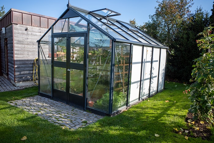
Image Source: metamorworks/Shutterstock.com
By Michael Parks, PE for Mouser Electronics
Published December 7, 2021
Introduction
Over the past few years, Arduino has steadily grown beyond its humble roots as a singularly-focused platform for students and hobbyists into a wide-ranging portfolio of development boards. From education to machine learning, and from industrial controls systems to the Internet of Things, the modern Arduino ecosystem has something for almost every embedded system use-case. The Arduino Pro Family line of products offer robust hardware meant for the exacting demands of many professional applications without sacrificing the ease of programming or integration with third-party hardware.
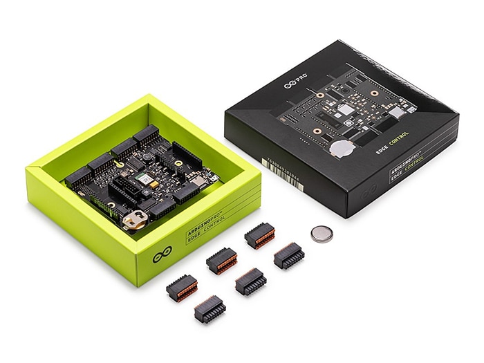
Figure 1: Arduino is moving into the professional engineering market with their Pro line of products, such as the agriculture-oriented Edge Control board. (Source: Mouser)
One such application area Arduino has targeted with their Pro Family products is the agricultural market. The Edge Control board (Figure 1) is a powerful embedded built specifically for remote monitoring and intelligent control of devices used in agricultural applications such as hydrostatic watermark sensors and water control valves. It is built to be powered by lithium ion batteries, sealed lead acid batteries, or photovoltaics so it can operate for long periods of time between servicing. Furthermore, it features two MKR board expansion slots so that additional functionality, such as sensors or wireless connectivity, can be added quickly and easily. This is very useful in that it allows developers to customize the solutions as needed. For example, depending on the location, it may be necessary to switch from GSM to LoRa communications.
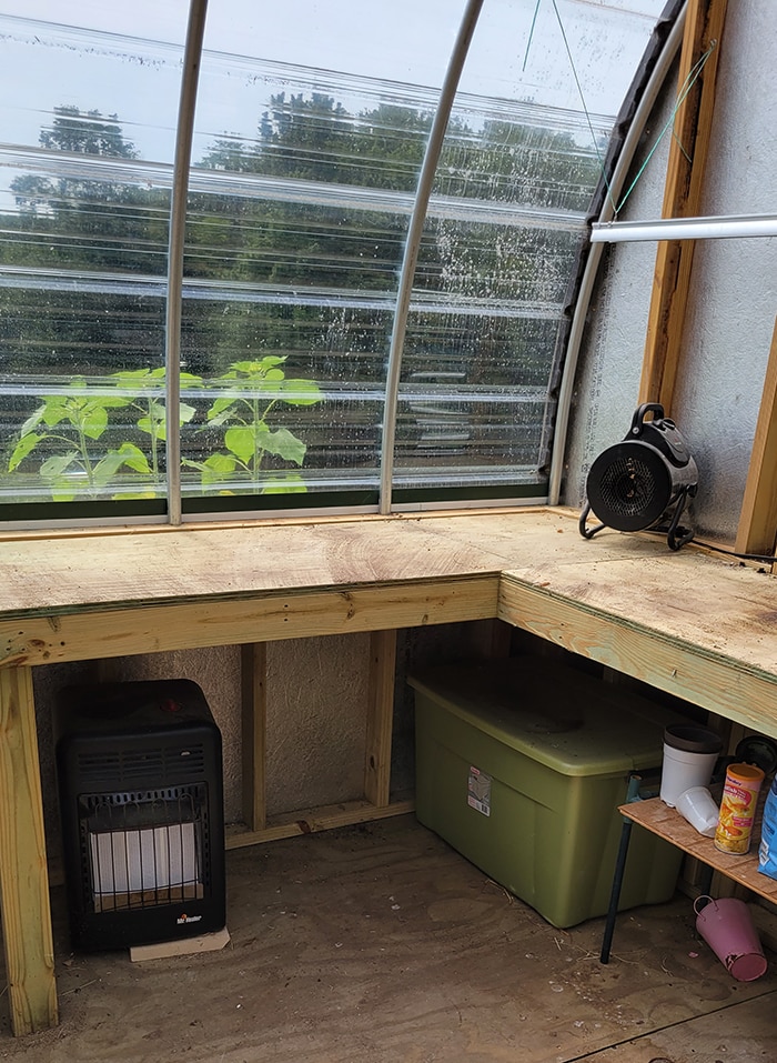
Figure 2: Greenhouse are becoming increasingly popular for individuals and families given recent supply chain issues. (Source: Green Shoe Garage)
Backyard gardens and greenhouses are enjoying a modern renaissance for many reasons, such as a desire to eat healthy while also lowering the grocery bill or to become more self-sufficient (Figure 2). In this project, we will leverage the Edge Control board to help improve our greenhouse crop yield by closely monitoring environmental factors such as temperature and sunlight exposure as well as automating mechanisms that can alter the environment to desired setpoints (e.g., turn a fan on to lower temperature or turn on growing lights to compensate for lack of sunlight). Lastly, we send all telemetry back to the cloud so we can monitor remotely as well as add a manual control feature to override the automation as desired by the end user.
Project Materials and Resources
Bill of Materials
You can visit this Mouser project share link to access the BOM along with the current pricing. As of the date this article was written, the BOM cost is about $380 (USD), before applicable taxes and shipping costs. Table 1 lists the items in the BOM.
Table 1: Remote Greenhouse Monitoring and Control BOM
| Quantity | Mouser P/N | Description |
|
1 |
782-ASX00029 |
MKR Environmental Sensor Shield |
|
1 |
782-AKX00034 |
Arduino Edge Control Board |
|
1 |
782-ABX00023 |
MKR1010 Wi-Fi Board |
|
1 |
485-1980 |
TSL2591 Light Sensor |
|
1 |
426-SEN0189 |
Water Turbidity Sensor |
|
1 |
426-SEN0249 |
Soil pH Sensor |
In addition, this project utilizes hardware built specifically for heavy agriculture applications, including a three-wire ball valve, a hydrostatic watermark sensor, and a relay control board. These should be readily available at retailers that specialize in farming and other agricultural products. Also, to mount the Edge Control carrier board to an enclosure, three M3-0.5 x 5mm machine screws are required.
Resources
All source files for this project are located on Mouser's GitHub repository. The repository is divided into three main folders including:
Documentation
The Documentation folder contains graphic files of schematics and other important reference materials.
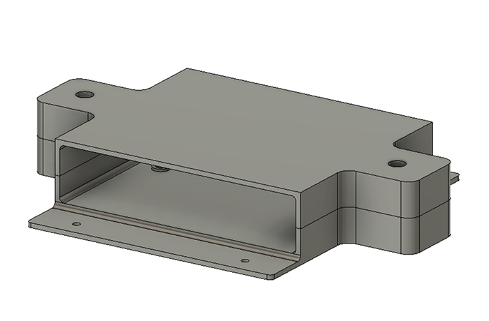
Figure 3: 3D model of a mounting device for the Edge Control board. (Source: Green Shoe Garage)
3D Files
The 3D Files folder contains the raw (in various formats) and STL files for the mounting bracket (Figure 3). These files are made specifically for this project and are ready to be 3D printed at your convenience.
Software
The Software folder contains the source code, including the following subfolders and associated files:
Greenhouse MKR 1010 Board:
mkr1010.inodfr_turbidity_sensor.hdfr_soil_ph_sensor.hsystem_settings.hthing_properties.harduino_secrets.h
Greenhouse Edge Control Board:
edgeControl.ino
More details about these files can be found in the Software section below.
Building the Project
The possibilities afforded by the Edge Control board are vast. It is great that every solution built around the Edge Control platform can be tailored to the specific needs of your particular greenhouse setup. For this particular effort, we will be interested in monitoring the following variables:
- Ambient temperature
- Relative humidity
- Illuminance (Foot Candles over course of day)
- Soil pH level
- Water turbidity
You might point out that water turbidity (the amount of particulate matter suspended in water) is odd for a greenhouse. In this particular greenhouse, the client uses a small pond of goldfish to generate the “fertilizer” to sustain the plants in a sustainable manner.
In addition to monitoring the environment inside the greenhouse, we wish to add automatic and manual control over the following devices:
- Ventilation fan
- Water valve
Hardware Setup
At this greenhouse there is Wi-Fi connectivity already, so the project leverages the MKR1010 board to allow for bidirectional communication between the Edge Control board and the Arduino IoT Cloud service. Solutions are available for GSM, LoRa, Sigfox, and NB-IoT networks as well. To allow the device to be moved around the greenhouse as needed, it will be powered by a sealed lead acid battery.
While the MKR Environmental board does have an onboard light sensor, we will not be using it since the Edge Control board I (Figure 4) will be mounted in such a way as to avoid direct exposure to sunlight. This is done to ensure only the ambient temperature is measured and to keep the board from overheating due to direct exposure to the sun. However, we do want to measure the amount and duration of sunlight exposure that plants receive, so an externally wired light sensor is used to collect sun exposure datapoint.
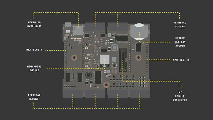
Figure 4: Key feature of the Arduino Control board. (Source: Arduino)
Assembling the electronics hardware is rather straightforward and only minimal tools will be required. Let’s begin:
- Place the coin cell battery into the coin cell slot of the Edge Control board. Mind the polarity of the battery. NOTE: This is critical, as failure to place the battery into the Edge Control board can result in bricking the board. You have been warned!
- Place the MKR1010 expansion board (Figure 5) into the MKR2 expansion slot. Ensure that the MKR1010 board is placed correctly into the Edge Control board expansion slot as the MKR boards are not keyed and can be easily placed onto the carrier board incorrectly.
- Place the MKRENV environmental sensor shield atop the MKR1010 board. Again, ensure the proper placement as the boards are not keyed and the board can be put in backwards.
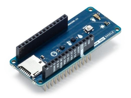
Figure 5: Arduino Edge Control board has two expansion ports compatible with the MKR form factor. (Source: Mouser)
At this point, the data-processing and communications components of the Edge Control board are fully assembled. Next, we will add the sensors and actuators to the Edge Control carrier board. Since the main assembly will be mounted in a way as to be shielded from direct sunlight, an external TSL2591 light sensor (Figure 6) will need to be wired into the MKRENV shield and ran to a location within the greenhouse where it can be exposed to direct sunlight. Let’s install the external light sensor:
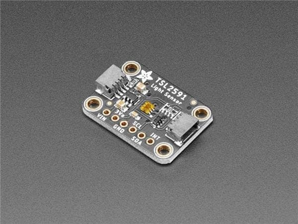
Figure 6: The TSL2591 light sensor breakout board. (Source: Mouser)
- Solder the male headers to the TSL2591 light sensor breakout board.
- Connect a wire to
SCLpin of the breakout board. Then connect the other end of the wire to pinD12of the MKR1010 (D12 is also connected to the hardware I2C controller) - Connect a wire to
SDApin of the breakout board. Then connect the other end of the wire to pinD12of the MKR1010 (D12 is also connected to the hardware I2C controller) - Connect a wire to
GNDpin of the breakout board. Then connect the other end of the wire to pinGNDof the MKR1010. - Connect a wire to
VINpin of the breakout board. Then connect the other end of the wire to pin3.3Vor5Vof the MKR1010. The breakout board contains hardware to step-down 5V to 3.3V.
We will use a hydrostatic watermark sensor (Figure 7) to monitor the water levels in the fish tank and control a 3-wire motorized ball valve to add water as needed. A voltage divider circuit with the sensing mechanism acting as variable resistor to translate the height of water to a voltage. The status of the water valve and the water level measurement will be fed back to the MKR1010 board via an I2C-based RPC, which in turn will be sent up the Arduino IoT Cloud. Let’s begin by wiring in the 3-wire motorized ball valve to the Edge Control carrier board:
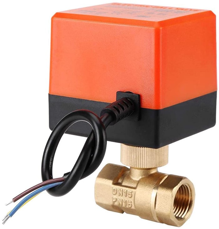
Figure 7: A 3-wire motorized ball valve. (Source: Green Shoe Garage)
- Connect
GNDwire of the ball valve to the5V Analog Inpin of the Edge Control board. - Connect
OPENwire of the ball valve to theJ9 Latching Out 1Ppin of the Edge Control board. - Connect
CLOSEwire of the ball valve to theJ9 Latching Out 1Npin of the Edge Control board.
There are latching output ports onboard the Edge Control board that include drivers. Thus, no external drivers are required. The latching output pins are referenced to VBAT.
Next, let’s turn our attention to the hydrostatic watermark sensor. Such a transducer works by translating head of pressure exerted by a fluid onto the sensing diaphragm to a signal, proportional to the pressure. Such a signal may be a 4-20mA current or 0-10Vdc voltage. Be aware that 0.1 bar of pressure is equal to 1m of fluid depth. To connect the hydrostatic watermark sensor, follow these steps:
- Connect the common wire of the sensor to pin
J8-17(common to all hydrostatic watermark sensors,J8-18also serves as a common). - Connect the analog signal wire of the sensor to pin
J8-1.
One way to measure the quality of a contained body of water is to measure turbidity, which is defined as the amount of “cloudiness” caused by particles suspended in the fluid. For this greenhouse, the concern is that the water does not get too dirty from the fish. The turbidity sensor (Figure 8) will be connected to the MKR1010 and wired as such:
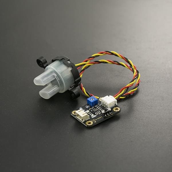
Figure 8: A turbidity sensor measures the "cloudiness" of a fluid. (Source: Mouser)
- Connect sensor to the adapter board using the included wiring harness.
- Connect the
GNDpin of the sensor adapter board to theGNDpin of the MKR1010. - Connect the
5Vpin of the sensor adapter board the5Vpin of the MKR1010. - Connect the
OUTPUTpin of the sensor adapter board to the analog input pinA0of the MKR1010. - Set the
A or Dswitch to the analog position,A.
Finally, we will monitor the pH levels of the soil to ensure that soil contains the right balance of minerals needed to maximize the yield of fruits, vegetables, and other plants being grown within the greenhouse. A soil pH level sensor (Figure 9) will be connected to the MKR1010 by completing the following steps:
- Connect the spear tip pH sensor to the adapter board with the BNC connector.
- Connect the
GNDpin of the sensor adapter board to theGNDpin of the MKR1010. - Connect the
5Vpin of the sensor adapter board the5Vpin of the MKR1010. - Connect the
OUTPUTpin of the sensor adapter board to the analog input pinA2of the MKR1010.
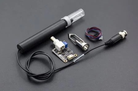
Figure 9: A pH sensor monitors the health of the soil. Keeping the soil healthy is key to successful plant growth. (Source: Mouser)
Setting up the Software Development Toolchain
To develop the firmware for this project, we will be using the Arduino IDE, which can be downloaded from here. By default, the libraries needed to program the Edge Control and the MKR1010 are not installed when the IDE installed. Let’s grab those libraries first by using the Board Manager wizard. Search for the following board families:
Mbed OS Edge BoardsSAMD Boards
Additional support files are required for the external light sensor, the MKRENV sensor board, connecting to the Arduino IoT Cloud and communication between the carrier and expansion boards. The follow libraries are available from the Arduino IDE built-in Library Manager. Be sure to let the IDE wizard download all the support libraries as well.
Adafruit_TSL2591.hArduinoIoTCloudArduino_ConnectionHandler.hArduino_MKRENV.hopenmvrpc.h
Software Development
This project presents a unique opportunity to learn how to get two individual embedded processors to communicate with each other. The Edge Control serves as the “carrier board” (think motherboard in desktop computer parlance); the MKR1010 is considered an “expansion board”. Communication between the two boards will be accomplished via Remote Procedure Calls (RPC).
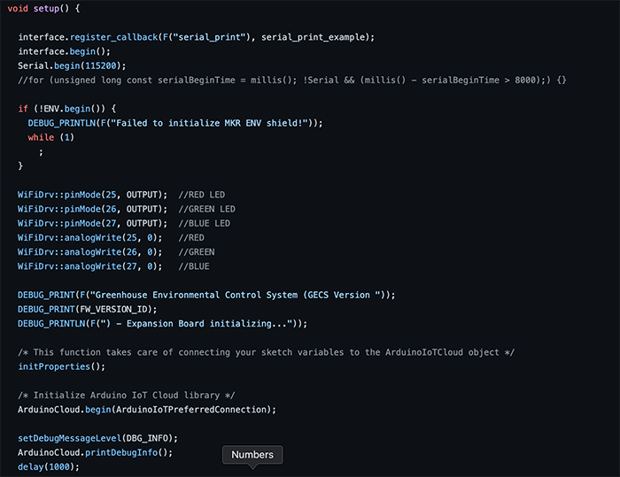
Figure 10: The source code for the project is split over many files, written in the C-derived Wiring language. (Source: Green Shoe Garage)
For those who have experience with programming within the Arduino ecosystem, programming the Edge Control board will be familiar. However, there are enough significant differences that it will be worth your time to read the Edge Control library documentation. These new “Pro” boards are intended to operate in highly demanding environments without sacrificing the ease of development that Arduino has become known for. In short, think of it as expanding the core Arduino codebase to include new, high-level functions that allow a developer to easily interface with the Edge Control unique hardware features such as the hydrostatic watermark sensor inputs, latching relay command outputs, and the galvanically isolated solid-state relays.
Programming the Edge Control board is accomplished via the onboard micro-USB port. Please note that the USB port is only for programming the board; it cannot be used to power the Edge Control board in the field.
Five files of interest will be found in the Software folder of the GitHub repository project structure. Files with the .ino extension are the files that will be loaded onto the microcontrollers. They contain the core functionality that each board is to perform. The files with the .h extension provide compartmentalization of sensitive data and/or remove the complexity of interacting with sensors and actuators from the .ino files to make the source code easier to read and debug.
Project Specific Files
The project-unique files created specifically for this project include:
mkr1010.inodfr_turbidity_sensor.hdfr_soil_ph_sensor.hsystem_settings.hthing_properties.harduino_secrets.hedgeControl.ino
Edge Control Library Unique Functions
As mentioned previously, there are numerous unique functions in the Edge Control library that one must be aware of to properly operate this particular board. In addition to the standard Arduino functions, variables, and control structures, the Edge Control library adds additional code to seamlessly interact with the unique hardware components. Some of these unique functions include:
EdgeControl.begin():Initializes the Edge Control board to the default power settings.Power.on(PWR_3V3):Turns the 3V power rail on.Power.on(PWR_VBAT):Turns the 5V power rail on.Power.on(PWR_MKR2):Supplies power to the VIN pin on the #2 expansion board interface.Expander.begin():Enables the expander pins.Latching.begin():Configures the expander pins as outputs.Watermark.enable():Initializes the internal hardware that operates the watermark sensors.Watermark.calibrationMode(OUTPUT):Sets the calibration mode for the watermark sensor pin to an output (similar to thepinModefunction)Watermark.calibrationWrite(LOW):Zeroes out the input of the watermark sensor pin by grounding the pin briefly.Watermark.begin():Put the watermark sensor pins to normal operation.Watermark.commonMode(OUTPUT):Put the watermark sensor into a common mode of operation.Watermark.commonWrite(HIGH):Sets the watermark sensor input pins high.Watermark.analogRead(pin):Reads the voltage on the watermark sensor outputs.
Key Variables and Constants
There are two variables in the arduino_secrets.h file that must be edited for the MKR1010 to connect to your Wi-Fi network:
SECRET_SSID "YOUR-NETWORK-SSID-HERE"SECRET_PASS "YOUR-WIFI-PASSWORD-HERE"
Once the MKR1010 is connected to the Internet, it must then connect to the Arduino IoT Cloud. This is accomplished with two variables that are given to you during the setup process. These variables are stored in the file named thing_properties.h:
THING_ID "YOUR-THING-ID-HERE"BOARD_ID "YOUR-BOARD-ID-HERE"
There are numerous variables to be tweaked with in the system_setting.h file to help calibrate the device to your requirements. These include:
NUM_SENSOR_READINGS_TO_STORE 10: It is a good practice to not make decisions based on individual sensor data points, but rather to take a running average. In this project, we are using a running average over the last ten sensor readings.
Hysteresis is an importance concept with control systems. It is defined as the dependence of the state of a system on its history. For this project we are controlling a fan based on the sensed ambient temperature. If the temperature were to frequently float above and below the setpoint the fan would turn on and off rapidly, leading to a likely failure. Complex systems utilize a Proportional-Integral-Derivative (PID) controller to alleviate such issues. For less complex systems, it will suffice to use two different setpoints, as was done here. With regard to temperature and fan control, the fan will kick-on once the temperature reaches 90F. But the temperature must fall below 87F before the fan turns off. This will prevent that fan from rapidly turning on and off should the temperature hover right around 90F, plus or minus a few fractions of a degree. These variables can and should be modified for your needs.
const float TEMP_HIGH_HIGH = 90.0const float TEMP_HIGH_LOW = 87.0const float TEMP_LOW_HIGH = 53.0const float TEMP_LOW_LOW = 50.0
const float HUMIDITY_HIGH_HIGH = 63.0const float HUMIDITY_HIGH_LOW = 60.0const float HUMIDITY_LOW_HIGH = 33.0const float HUMIDITY_LOW_LOW = 30.0
const float PRESSURE_HIGH_HIGH = 1000.0const float PRESSURE_HIGH_LOW = 995.0const float PRESSURE_LOW_HIGH = 905.0const float PRESSURE_LOW_LOW = 900.0
const float LOW_WATER_MARK = 0.74const float HIGH_WATER_MARK = 1.5
const float MAX_ALLOWABLE_TURBIDITY = 1.0
NOTE: Documentation for the Edge Control board heavily utilizes the auto datatype. Like int, float, or bool, auto is a datatype keyword. Unlike the first three datatypes, auto is different in that it lets the compiler infer the actual datatype during initialization. This helps with code reuse, avoids the need for conversion, and helps with robustness (e.g., should a function return type change, code will still run). Note that failure to initialize an auto variable at declaration will result in a compile-time error.
Connecting Board to the Arduino IoT Cloud
This project will leverage the Arduino IoT Cloud to provide the cloud backend to consolidate the data from our sensors and to allow the end user to remotely control their device (Figure 11). Arduino IoT cloud allows developers to create elegant graphic displays of the sensor data and controls, accessible both from the browser and a dedicated smartphone app (available for both iOS and Android). More information on connecting your MKR1010 to the Arduino IoT Cloud can be found here. This step must be completed before proceeding.
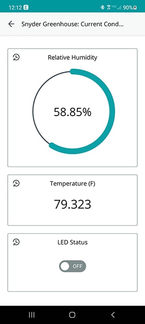
Figure 11: Building on the Arduino IoT Cloud platform gives developers a quick and easy way to create smartphone and browser-based apps for their IoT solutions. (Source: Green Shoe Garage)
Next, it will be necessary to create a dashboard of all the pertinent data points our device is sending to the Arduino IoT Cloud. For more information on creating a dashboard, click here.
Final Assembly and Installation
Now it is time for final assembly. Begin by removing the MKR1010 board from the Mount the Arduino Edge Control carrier board. This will expose one of the three mounting points. Mount the Edge Control board into the mounting device (Figure 12) using three M3-0.5 x 5 mm machine screws.
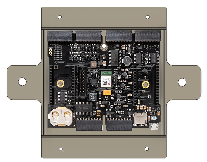
Figure 12: Mounting the Edge Control board in the mounting enclosure provides protection and easy install of the Edge Control board. (Source: Green Shoe Garage)
Next, find a place in the greenhouse where the device will not be exposed to direct sunlight and mount with four wood screws as appropriate. Run the wire for the external sensors as needed.
Lastly, a few troubleshooting tips:
- Do not forget to set the
A or D switchof the water turbidity sensor to the analog position,A. - Ensure that your local Wi-Fi network is accessible inside the greenhouse. A Wi-Fi extender may be necessary.
- Ensure the soil pH sensor has been calibrated following the prescribed guidelines.
- The soil must be moist for the tip spear pH sensor to accurately take a pH reading.
- Ensure the Edge Control carrier board has a good coin cell battery inserted in the battery holder.
- A greenhouse can be a rather dirty environment. Ensure that boards are free of debris that might be inducing shorts. It may be necessary to mount the device in a more robust enclosure if the environment is prone to significant debris and dirt.
- There are lots of external wires. Ensure wires are securely connected. Pay particular attention to the wires providing power from the battery to the Edge Control carrier board, the ball valve controller, and the hydrostatic watermark sensor.
Project in Action
With the project finally assembled and installed into the greenhouse, it’s time to start monitoring and controlling the greenhouse from our smartphone. Make sure the device is receiving power. Wait a few seconds for the device to establish a connection to the internet. Launch the Arduino IoT Cloud Remote app on your iOS or Android device. Navigate to the dashboard that was created previously.
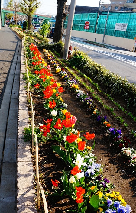
Figure 13: After all the hard work, fruits, vegetables, and beautiful flowers are the reward. (Source: Green Shoe Garage)
In the code provided, there is a mechanism within the browser and smartphone app to switch between a manual operation mode and the automated mode. This allows the user to remotely control the fan or lighting, regardless of the current conditions or set points.
With everything up and running, this greenhouse is now fully monitored and automated. There are, however, plenty of available I/O and expansion capabilities to grow this project to meet your needs. Also, be sure to configure the set points to your specific climate and the plants that you are growing. If you are unsure of the correct conditions, we recommend consulting with a local horticulturist or nursery for more information.