Moving the Goods: Exploring the Arduino Opta PLC

Image Source: Mouser Electronics
By Michael Parks for Mouser Electronics
Published August 29, 2023
Programmable logic controllers (PLCs) are the cornerstone of modern industrial automation, providing a robust and flexible platform for controlling machinery and processes. In a nutshell, PLCs are industrial digital computers adapted for controlling manufacturing processes such as assembly lines, robotic devices, or any activity that requires high reliability, ease of programming, and process fault diagnosis. PLCs were developed in the late 1960s to replace the complex relay and timer systems in use at the time. Richard Morley is often credited with inventing the first PLC, the Modicon, in 1968. Since then, the technology has evolved, and PLCs have become essential components in numerous application areas, including machine control, building automation, predictive maintenance, data logging, remote monitoring, and security.
A PLC consists of several key components:
- Processor (CPU): This controls all the PLC's activities. It processes the data from input modules and sends signals to output modules.
- Input/output modules (I/O): The PLC can interact with the outside world. Inputs receive data from sensors and human-machine interfaces (HMIs), while outputs send signals to actuators and other devices.
- Memory: This stores the user's program and other information needed for the process.
- Communication ports: These enable communication between the PLC and other devices, such as computers, other PLCs, and network systems.
- Power supply: This provides the necessary power to run the PLC and its I/O modules.
Recently, Arduino entered the PLC market with the Opta platform (Figure 1), a secure, easy-to-use micro PLC with industrial Internet of Things (IIoT) capabilities. It was designed in partnership with Finder, a leading industrial and building automation device manufacturer. The Opta allows professionals to scale up automation projects while leveraging the Arduino ecosystem. It supports both Arduino sketch and standard PLC languages, including Ladder Logic Diagram (LD) and Function Block Diagram (FBD).
Figure 1: Arduino has entered the Programmable Logic Controller market with the Opta family of PLCs. (Source: Arduino)
The Opta comes in three models: Arduino Opta Lite, Arduino Opta RS485, and the most feature-rich, the Arduino Opta Wi-Fi®. The Opta has a powerful STMicroelectronics STM32H747XI dual-core Arm® Cortex®-M7+M4 MCU that allows users to perform real-time control, monitoring, and implement predictive maintenance applications. Depending on the model, the Opta also has multiple choices for network connectivity, including USB, Ethernet, and Wi-Fi® / Bluetooth® Low Energy, in addition to industry-specific protocols such as RS-485. The Opta is a DIN rail-mountable device with a highly reliable design operating at industrial temperature ranges (-20°C to +50°C) thanks to a dual-core architecture without external cooling. Key features of the Arduino Opta include:
- Security: The Opta has a secure boot process and supports TLS 1.2 for secure communication.
- Ease of development: The Opta can be programmed using the Arduino IDE or the Finder PLC IDE.
- Professional-grade IIoT capabilities: The Opta has multiple connectivity options and can be connected to the internet and used for remote monitoring and control.
In this project, we will design a proof-of-concept conveyor system to sort packages based on size. The project will allow us to explore several concepts concerning the Arduino Opta, including developing with both the Arduino 2.0 IDE and the Arduino PLC IDE. We will also walk through the process of interfacing hardware with a PLC. And finally, we will see what it takes to connect the Opta to the internet via the Arduino Cloud.
Bill of Materials and Tools
As of the publication date, the total BOM costs approximately $300 (USD; Table 1).
Table 1: Project BOM
Mouser P/N | Part Description | QTY |
Arduino Opta Wi-Fi | 1 | |
IR break-beam sensor (transmitter and receiver) | 2 | |
10kΩ Resistor | 2 | |
Breadboard | 1 | |
Jumper wires | 1 | |
Step Down (12V to 5V) voltage regulator | 1 | |
Relay Control Board with Modbus RTU | 1 | |
DC Motor | 2 | |
DIN Mounting Rail (Optional) | 1 |
In addition to the BOM, the following tools are recommended:
- Small Phillips head and flathead screwdrivers
- Wire cutter/stripper
- Small needle nose pliers
- Digital multimeter
- High-speed internet connection
- PC running Windows 10 or newer
Resources
Hardware Build
This project will use two infrared (IR) break-beam sensors to detect the packages and their sizes. These sensors are commonly used in applications such as object detection, counting, and security systems. They come in pairs, with the transmitter having two wires and the receiver having three wires.
We will stack the pairs of sensors atop each other. If a small box passes through, it will activate only one sensor. A larger box will break both beams and activate both sensors. Lastly, as these are 5V sensors, we will need to reduce the voltage from 12V to 5V using a voltage regulator. Figure 2 shows how these sensors connect to the Opta.
Figure 2: Wiring diagram showing how to connect the hardware. Note that the pull-up resistors are optional, if needed connect IR receiver OUT pin to 5V from buck converter. (Source: Green Shoe Garage)
Use the following steps to connect the IR break-beam sensors:
- Connect the 12V source pin of the Opta to the positive (+) input of the voltage regulator.
- Connect the GND (-) source pin of the Opta to the negative (-) input of the voltage regulator.
- Connect the transmitter's (IR LED's) VCC (power) pins to the positive (+) output of the voltage regulator.
- Connect the transmitter's GND (ground) pins to the negative (+) output of the voltage regulator.
- Connect the receiver's VCC (power) pins to the positive (+) output of the voltage regulator.
- Connect the receiver's GND (ground) pins to the negative (+) output of the voltage regulator.
- For the upper break beam sensor, connect the OUT (signal) pin to the I3 digital/analog input terminal.
- For the lower break beam sensor, connect the OUT (signal) pin to the I4 digital/analog input terminal.
- You may want to add a pull-up or pull-down resistor, depending on your specific module. If you're using a pull-down resistor, connect a 10kΩ resistor between the signal pin and the ground.
Next, connect the Opta PLC to a circuit board designed to interface DC motors. The two boards will communicate via RS485-bus Modbus RTU commands (half-duplex without termination resistance). The control board contains relays that will control DC motors that will drive the conveyor that moves the package along.
The Opta board contains a dedicated RS485 hardware port in the form of recessed screw terminals atop the enclosure. The pins are labeled A(-), GND, and B(+). The motor control board has corresponding pins in addition to a VIN pin for power. Use the following steps to wire the PLC to the controller:
- Connect A(-) of the PLC to A(-) of the control board.
- Connect B(+) of the PLC to B(+) of the control board.
- Connect the GND of the PLC to the GND of the control board.
- Connect 12V of the PLC to the VIN of the control board.
Lastly, we must connect the 12V DC motors to the control relays. We want each motor to rotate in the opposite direction of the other. The motors will be powered from the Opta 12V ports.
- Connect the 12V pin of the Opta to NO1 of the control board
- Connect COM1 of the relay control board to one of the leads of the DC motor.
- Connect the other lead of the DC motor to the GND pin of the Opta.
- Connect the 12V pin of the Opta to NO2 of the control board
- Connect COM2 of the relay control board to one of the leads of the second DC motor. Ensure the leads are reversed from the first motor to ensure they rotate in opposite directions.
- Connect the other lead of the second DC motor to the GND pin of the Opta.
Software Development
There are a few different options for programing the Opta, including both the traditional Arduino IDE 2.0 and the web editor. The Opta is also compatible with Arduino PLC IDE for programming in languages traditionally used in industrial automation applications. The Opta Wi-Fi® model can also connect to the Arduino IoT Cloud for receiving telemetry and remote control via a web browser or the Arduino IoT Cloud Remote smartphone app.
Since one of our requirements is for the PLC to communicate back to the cloud for remote monitoring, we will start at the Arduino IoT Cloud dashboard to provision our new device (Figure 3). To begin, download and install the Arduino Create agent, allowing the device to communicate with the Arduino Cloud backend. Download the agent and review the setup documentation. Once installed, connect the Opta with a USB Type-C cable to the developer workstation computer running the Create agent.

Figure 3: Provisioning a new device onto the Arduino IoT Cloud. (Source: Green Shoe Garage)
First, we can provision our Opta into the Arduino IoT Cloud environment by simply navigating to the Devices tab, clicking the Add button, and completing the setup wizard. This step will establish the security keys that will allow the Opta to communicate via the IoT Cloud secretly. We will also need to create a sort of “digital twin” (known as a "thing" in the Arduino environment) for the Opta (Figure 4). To do so, click the Things tab and then click the Create button. Check out the technical references here for more information on provisioning the Opta for the IoT Cloud.

Figure 4: Setting up the digital twin or "thing" of our Opta PLC. (Source: Green Shoe Garage)
Once finished, the PLC should appear as connected to the IoT Cloud. You can also access the web-based code in the desktop IDE if you sign in with your Arduino credentials.
Code Overview
Let’s begin by taking a look at the critical files of the project:
- main.ino does the majority of the work of setting up the device and running the main loop. Most of the project-specific source code will be found here.
- thingProperties.h contains the function calls that connect the physical PLC to its virtual twin thing in the cloud.
- arduino_secrets.h contains the Wi-Fi® SSID and password that allows the Opta to connect to the local wireless network.
- #define SECRET_OPTIONAL_PASS "NETWORK_PASSWORD"
- #define SECRET_SSID "NETWORK_NAME_HERE"
Key Libraries, Functions, and Variables
In addition to the libraries included by default, we will need to add the following libraries via the #include statement:
- ArduinoModbus.h contains the code necessary to process Modbus RTU communication packets.
- ArduinoTCloud.h allows the Opta to connect to the Arduino IoT Cloud service.
- Arduino_ConnectionHandler.h provides a ConnectionManager to control connection and disconnection, property-change updates, and events callbacks.
These libraries are needed primarily for the Opta to talk to the DC motor controller board. The board communicates via the Modbus RTU serial communication protocol with the following settings:
- Baud rate: 9600 bps
- Number of Data Bits: 8
- Parity Bit: No
- Stop Bits: 1
Following are some of the key functions and variables for Modbus communication found inside the main.ino file:
- byte controlBoardAddress = 0x01 sets the device address of the motor control board.
- int motor1 = 1 is the register for the motor to control the conveyor when a tall package is detected.
- int motor2 = 2 is the register for the motor to control the conveyor when a short package is detected.
- int motorTimeOn = 5000 sets the duration for how long the conveyor runs after a package is detected.
- ModbusRTUClient.begin(9600) starts the Modbus functionality at the given baud rate.
- void holdingRegisterWrite(int dev_address, uint8_t reg_address, uint8_t holding_write)
- int dev_address: The address of the motor control board may vary by manufacturer, so verify with your board’s documentation.
- uint8_t reg_address: The register address where commands will be written for the motor control board to execute. The register number corresponds to the physical relay board number. This can be a value between 0x00 and 0x0F.
- uint8_t holding_write: The commands that are written to the registers to control the relays. The commands are:
- 0x0100: Relay ON
- 0x0200: Relay OFF
- 0x0300: Toggles the state relay
- ModbusRTUClient.lastError() returns a string containing the last error message generated by the Modbus.
Next, let’s examine the code for the beam break sensors. We can configure these using a few different methods, including as inputs to an interrupt so we can handle a new package in a timely manner. Recall that we have two sets of transmitter/receiver pairs. The transmitters are constantly on, so there is no code for them. We will handle the receiver signal in the code. Note that these sensors are ACTIVE LOW, so the PLC will see 0V when the beam is broken due to the presence of a package. Table 2 provides some of the key functions and variables:
Table 2: Hardware Pin Callout
Hardware Pin Name | Software Pin Name | Functional Name |
I3 | A2 | PIN_A2, Lower Beam Break Sensor |
I4 | A3 | PIN_A3, Upper Beam Break Sensor |
- void setup()
- pinMode(A2, INPUT): The lower beam break sensor
- pinMode(A3, INPUT): The upper beam break sensor
- attachInterrupt(digitalPinToInterrupt(A0), lowerBeamBreak_ISR, LOW): If the lower beam break sensor is tripped, we know there is a package. We will then check the upper beam break sensor to determine if the package is short or tall.
- void lowerBeamBreak_ISR(): The interrupt service routine (ISR) will detect an object disrupting the lower beam break sensor.
The last major chunk of code is reserved for the Wi-Fi® communication of telemetry back to the Arduino IoT Cloud. The functions used to enable cloud communication are as follows:
- void setup()
- initProperties() initializes the “thing” properties to allow Opta to communicate with the IoT Cloud.
- ArduinoCloud.begin(ArduinoIoTPreferredConnection) starts the communications over Wi-Fi®.
- setDebugMessageLevel(2) sets the granularity of debug messages. Per the documentation, the higher number, the more granular information obtained; the default is 0 (only errors), and the maximum is 4.
- void loop()
- ArduinoCloud.update() needs to be called through every iteration of the main loop to send telemetry data back to the cloud.
- thingProperties.h
- bool lowerSensorTripped is a variable to store the state of the lower beam break sensor. If set to TRUE, a package is detected. If only the lower beam break sensor is tripped, the package is small.
- bool upperSensorTripped is a variable to store the state of the upper beam break sensor. If set to TRUE, a package is detected. A large package is detected if both the upper and lower sensors are tripped.
- ArduinoCloud.addProperty(lowerSensorTripped, READ, ON_CHANGE, NULL) sends the status of the lower beam break sensor to the cloud.
- ArduinoCloud.addProperty(upperSensorTripped, READ, ON_CHANGE, NULL) sends the status of the upper beam break sensor to the cloud.
Arduino PLC IDE
An alternative approach for coding the Opta is using the Arduino PLC IDE, a software development environment that allows you to program PLC-compatible Arduino devices using IEC 61131-3 standard languages. It is free and open-source software and is available only for Windows. As of this article's publish date, the PLC IDE is also less feature-rich than some other PLC programming software available on the market. However, the Arduino PLC IDE includes a variety of features that make it a powerful tool for PLC programming:
- Support for five IEC 61131-3 programming languages: Ladder Diagram, Functional Block Diagram, Structured Text, Sequential Function Chart, and Instruction List.
- A unified programming environment for both Arduino and PLC programming.
- A variety of debugging tools to help you find and fix errors in your code.
- An easy-to-use and intuitive user interface.
The Arduino PLC IDE is a valuable tool for anyone who wants to program PLC-compatible Arduino devices. It is easy to use and configure and includes various features that make it a powerful tool for PLC programming.
Use the following steps to install and set up the Arduino PLC IDE software:
- Download the Arduino PLC IDE and the Arduino PLC IDE Tools from the Arduino website.
- Run the Arduino PLC IDE Tools installer and follow the installation instructions.
- Once the installation is complete, open the Arduino PLC IDE.
- Connect your Arduino PLC-compatible device to your computer using a USB cable.
- In the Arduino PLC IDE, click the Tools menu, then click Board and select your device.
- In the Port section, select the COM port that your device is connected to.
- Click the PLC IDE Bootloader button to download the bootloader to your device.
- Once the bootloader has been downloaded, click the Connect button to connect to your device.
- In the Device License section, enter your device's hardware ID and click the Activate button.
- You should now be able to program your Arduino PLC-compatible device using the Arduino PLC IDE.
For more information on setup and provisioning via the PLC IDE, visit https://docs.arduino.cc/tutorials/opta/plc-ide-setup-license#3-project-setup.
We have provided code that demonstrates how to use the PLC IDE (Figure 5) to program the Opta in our GitHub repository. For information on using PLC IDE with cloud support, click here. For information about Modbus and the PLC IDE, click here.
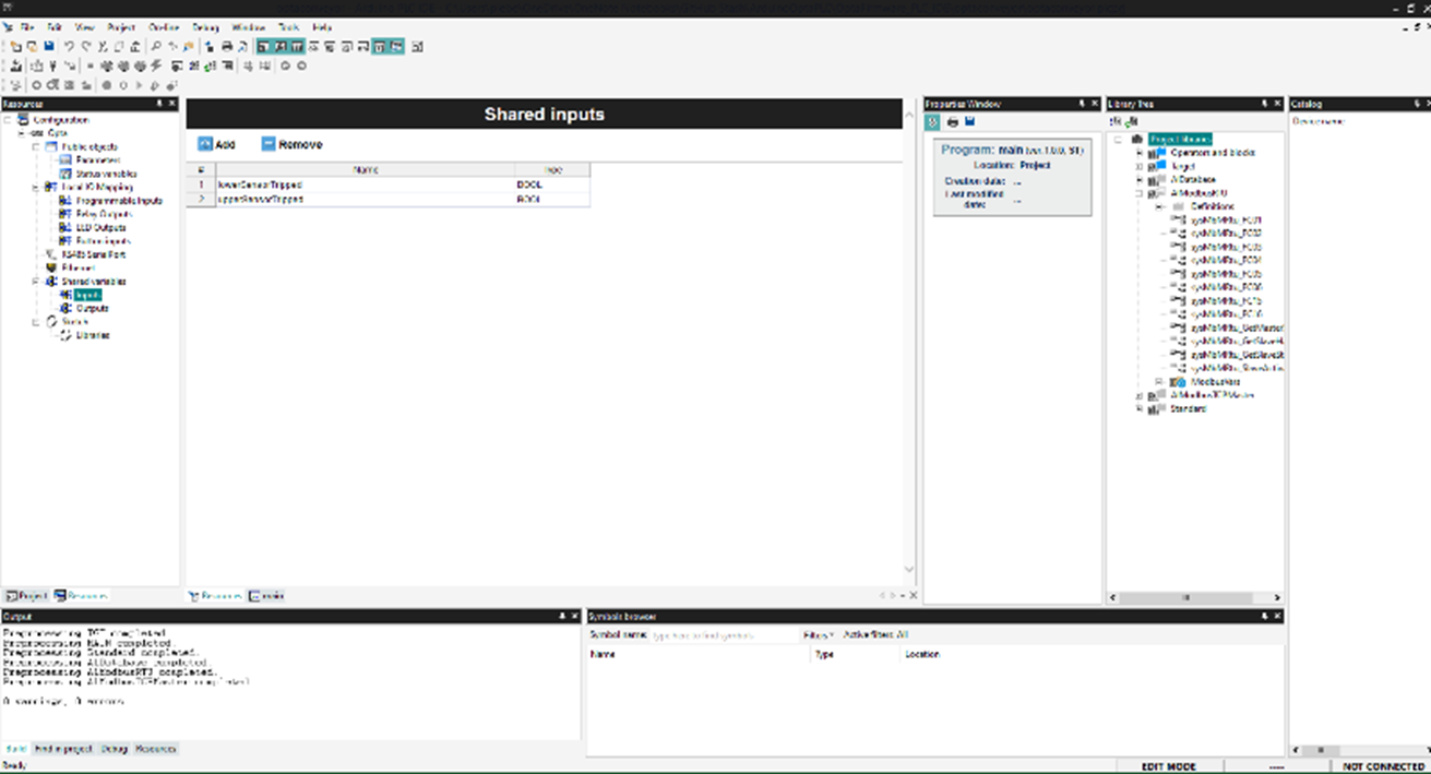
Figure 5: The Arduino PLC IDE provides industrial engineers tools that are more accustomed to for PLC development. (Source: Green Shoe Garage)
Final Assembly and Troubleshooting
With the hardware assembled and firmware flashed to our Opta PLC, let’s make final preparations to test our project. For our setup, the beam break sensors will be placed on either side of the conveyor belt (Figure 6). We will place the transmitters on the right side and the receivers on the left. Pay special attention to aligning the transmitters and receivers both horizontally and vertically so that a single large package will interrupt both sets of sensors simultaneously. Be careful to ensure wires are safely and neatly routed safely from any mechanical components, such as the motor and belts.
Figure 6: A small package will trip only the lower beam break sensor. (Source: Green Shoe Garage)
To view the telemetry data, either download and go into the Arduino Cloud Remote app or, in the browser, navigate to https://create.arduino.cc/iot/dashboards and select the appropriate dashboard (Figure 7).

Figure 7: The cloud-based dashboard to monitor conveyor activity. (Source: Green Shoe Garage)
Troubleshooting
If you find that you are having with your project, here are some tips that we discovered during development:
- The exact connections might vary depending on the specific IR break-beam sensor model, so make sure to consult the datasheet or any documentation that comes with your sensor.
- Ensure the IR LED (transmitter) and photodiode or phototransistor (receiver) are properly aligned to detect the break in the beam.
- Avoid exposing the sensor to direct sunlight or other sources of IR, as they may interfere with the sensor's operation.
- Ensure the serial communications are set to 9600 bps.
- If your device is not listed in the Arduino PLC IDE, you may need to install the corresponding Arduino core.
- If your device does not have a bootloader, you must flash it using the Arduino IDE.
- When swapping between IDE and PLC IDE, Wi-Fi® functionality may break. Using the Arduino IDE 2.0, you will need to run the Wi-Fi firmware updates by navigating to File > Examples > Portenta H7 board 747_system > example > wififirmwareupdater. Once the firmware has been flashed, start the serial monitor and complete the setup routine. Then flash your project firmware, and Wi-Fi® connectivity should be restored.
In Summary
PLCs have remained an integral part of industrial automation in an ever-changing technological landscape for over five decades. Arduino’s entrance into this class of embedded systems offers exciting new options for industrial system designers, especially for smaller operations with more limited resources. With their adaptability, resilience, and functionality, the family of Arduino Opta PLCs will surely become a trendsetter in the modern industrial world.
Swapping traditional PLCs with the Arduino Opta Wi-Fi® is a convenient way to add equipment to an IIoT system. The ability to use traditional PLC programming techniques should help lower the bar of adoption for system integrators accustomed to traditional PLC software development.
This project should give you a basic understanding of the principles of PLCs and the critical systems that enable our industrialized society to function. Whether you're an engineer, technician, or simply someone interested in technology, the Arduino Opta PLCs provide not just a powerful learning platform but also an inexpensive and functional solution for many practical automation and remote control applications.