An Introduction to Near Field Communications
By Greg Proehl, RF Memories and Transceivers, STMicroelectronics Europe B.V.
This introduction to Near Field Communications (NFC) is intended to provide an overview of NFC applications and solutions, including important terms and definitions, basic NFC infrastructure, NFC modes of communication, modes of operation, example use cases, and solutions/resources.
Welcome to NFC
NFC is an acronym for Near Field Communication. NFC is a short-range radio technology that enables communication between devices that are held in close proximity. The NFC Forum (www.nfc-forum.org) is standardizing the technology to be an open-platform across mobile devices and systems with which they interact. NFC systems are based on traditional High Frequency (HF) RFID, operating at 13.56MHz. The typical communication range for NFC can be up to 3 inches, and is dependent on the protocol used and the antenna design. Currently, the NFC standard supports different data transmission rates up to 424kbit/s. The principle mechanism of NFC communication between two devices is the same as traditional 13.56 MHz RFID, where there is both a master of the conversation and a slave. The master is called the emitter, or reader/writer and the slave is a tag or card.

The antennas of the Emitter and Tag are coupled via an Electromagnetic Field and this system can best be viewed as an Air-Core Transformer. An alternating current passes through the primary coil (Emitter) and this current induces a field thru the air, inducing current in the secondary coil (Tag). The Tag may use the current from the field to power itself. The design, configuration, and tuning of BOTH antennas determines the coupling efficiency from one device to the other. In general, inductive coupling thru air is very inefficient, and therefore, the read/write range is quite limited. Usually, the tag is a device containing an antenna, typically called an Inlay, as well as a small amount of memory. A tag is a passive device, and the power the device needs to operate comes from the electromagnetic field, generated by the emitter. RFID Inlays are attached to the EEPROM Memory for the antenna. These inlays are customized for the antenna design and application.

The NFC Forum has defined and classified tags to insure interoperability. Based on the tag type, the memory can be read only, rewritable, or writable once. NFC tags can be used in almost any application where you need a mobile device to get information, or have some sort of user interactivity. Data can be stored on the tags, such as URL addresses, Wi-Fi or Bluetooth pairing, SMS, Email, Vcard, and phone configurations. These data sets are formatted in a structure defined by the NFC Forum and can be used by the operating system directly to associate the data to natively installed applications such as the browser, texting, wireless or other programs. Custom data can also be stored on these tags and used by a custom application developed and installed by the user. This data does not have to follow all the structure requirements defined by the NFC Forum, but the OS manufacturer does have guidelines in their API definitions on how the data is extracted and manipulated. To ensure interoperability among different NFC tag providers and NFC device manufacturers, the NFC Forum has currently defined four tag types. More tag types are being defined in order to give developers of NFC devices competitive choices.
NFC Tag Types:
- Type 1: These cost effective tags are ideal for many NFC applications and are based on the ISO-14443A standard, have no data collision protection, 768 bits (96 bytes) of memory expandable to 16kbits (2k bytes) and have a communication speed of 106kbits/s.
- Type 2: Type 2 tags are similar to Type 1 tags and are based on the ISO- 14443A standard. Like Type 1 tags, they support 768 bits (96 bytes) of memory expandable to 16kbits (2k bytes) and have a communication speed of 106kbits/s. They provide anti-collision support, unlike the Type 1 tags.
- Type 3: Developed for the Japanese market, these tags use the Japanese Industrial Standard (JIS) X 6319-4, have anti-collision support, and are preconfigured at manufacture to be either read and rewritable, or read-only. The memory can be variable up to 8Mbits (1M bytes) per service and support communication speeds up to 424kbits/s, but the effective data rate on mobile devices is much lower, typically 106kbits/s. They are derived from the nonsecure parts of FeliCa tags and are typically expensive.
- Type 4: These tags are also very similar to Type 1 tags. They are based on the ISO-14443A and ISO-14443B standards, support anti-collision, and are preconfigured at manufacture to be either read and rewritable, or read-only. The memory can be variable up to 256kbits (32k bytes) per service and support communication speeds up to 424kbits/s, but the effective data rate on mobile devices is much lower, typically 106kbits/s.
Basic NFC Infrastructure:
The basic NFC Infrastructure is the same as is used by RFID. In NFC, the emitter is typically a cellphone or tablet. The mobile device acts as a NFC controller in the product, provides the energy-supplying electromagnetic field and reads the tags.
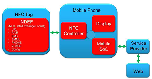
After determining if the tag can be read, the mobile product then reads the NDEF (NFC Data Exchange Format) area. The NDEF message is stored in the tag’s EEPROM memory and its structure is defined by the NFC Forum for interoperability.
NFC Modes of Communication:
- Active: In this mode, the target and the initiator devices have power supplies and can communicate with one another by alternate signal transmission.
- Passive: In this mode, the initiator device generates radio signals and the target device is powered by this electromagnetic field. The target device responds to the initiator by modulating the existing electromagnetic field.
NFC Modes of Operation:
NFC devices can operate in three different modes based on standards defined by the NFC Forum.
- Reader Mode: In this mode, the NFC-enabled phone can read or write data to any of the supported tag types in a standard NFC data format.
- Card Emulation Mode: An NFC-enabled phone acts as a reader when in contact with another device that is acting like a tag. For example, you can have a cellphone act like a tag or contactless card for interaction with existing readers.
- Peer to Peer Mode: In this mode, two NFC-enabled devices can exchange data and act as emitters. Any device at any time can act as the master of the conversation and control the conversation between two devices in this mode.
Choosing a solution
There are 4 basic use cases that are possible, depending on the requirements of the application. To identify a solution, first determine which of the four NFC use cases applies. Then, choose the right product for the mode of operation needed.
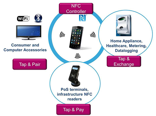
Tap & Pair
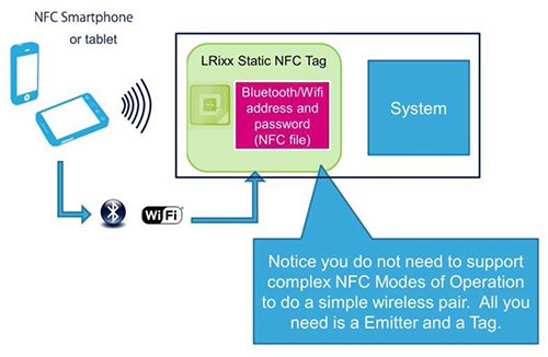
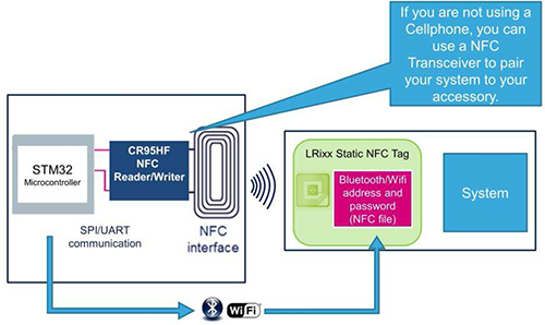
The Tap & Pair use case is mainly for automatically adding a wireless accessory to a cellphone or tablet 'connected device' list. You can use a Static NFC Tag, Dynamic NFC Tag, or NFC Controller in your accessory design.
Tap & Exchange
Tap & Exchange is a very similar use case to Tap & Pair, but Tap & Exchange allows for more data to be transferred to the cellphone or tablet than just wireless connection data. You can use a Static NFC Tag, Dynamic NFC Tag or NFC Controller in your application.

Tap & Pay
Tap & Pay is an extension to Tap & Exchange as you are providing information for payments, but the payment systems can vary depending on the level of security needed. You can use a Dynamic NFC Tag, NFC Transceiver or NFC Controller.
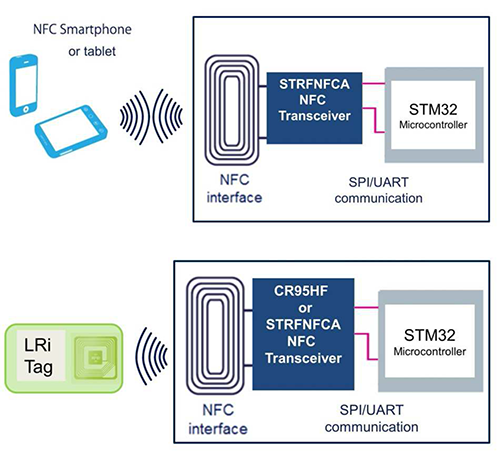
NFC Controller
NFC Controllers will support all Communication Modes of Operation and will have a connection to a secure element for local payments. These are the devices used in Cellphones and Tablets.
