Greenhouse Lighting: Automation and Control

By Michael Parks, P.E., for Mouser Electronics
In a previous horticulture-focused project, we examined how temperature, humidity, moisture, pH levels, and CO2 levels affect plant growth. Here, we examine another key ingredient for plant photosynthesis, which is exposure to light. This follow-on project will allow those with a green thumb to monitor and remotely control artificial light exposure. Controlled Environments horticulture (CE) is a fancy way of saying growing plants with the aid of digital technology. It is becoming an increasingly important mechanism to assist in stabilizing the food supply chain for the planet. In some scenarios, like indoor vertical farms, access to sunlight is not a guarantee. Smart use of artificial lighting is crucial in such situations.
This project will utilize Medium One, an end-to-end IoT cloud platform to allow an end user to monitor, automate, and remotely control the artificial lighting in a horticulture-oriented facility, be it a greenhouse, vertical farm, or some other environment that requires such functionality.
Materials
This project is built around Microchip’s Xplained board series, which is ideal for rapid prototyping efforts. This project will utilize the SAM W25 Xplained Pro Evaluation Kit. This development board is powered by the Arm® Cortex®-M0+ based ATSAMD21G18A microcontroller. Other key components will include:
- Sparkfun TEMT6000 ambient light sensor
- Switching Power Supply rated at 75.6W; 2.1A @ 36V
- Microchip MIC3202 HB LED Driver
- LED Lighting Bar
Bill of Material (BOM)
The BOM is listed below. Alternatively, you can visit mouser.com and grab all the parts you need from a pre-built shopping cart, just click here. As of this writing, the below BOM is about $125 (USD) without the LED strip. Including the LED strip puts the cost at just over $400 (USD). Table 1 lists the items in the BOM.
| Quantity | Mouser P/N | Description |
| 1 | 474-BOB-08688 | Optical Sensor Development Tools Ambient Light Sensor B/O TEMT6000 |
| 1 | 556-ATSAMW25-XPRO | WiFi Development Tools (802.11) SmartConnect ATSAMW25-XPRO board |
| 1 | 579-ADM00962 | LED Lighting Development Tools MIC3202 HB LED Driver Evaluation Board |
| 1 | 709-LRS75-36 | Switching Power Supplies 75.6W 36V 2.1A |
| 1 | 339-37132200100 | LED Lighting Fixture |
Tools and Other Resources
Here is a list of recommended tools to have on hand in order to complete this project:
- Windows-based computer running the Arduino IDE or Atmel Studio 7.0
- A Wi-Fi network (802.11/b/g/n/ac)
- Wire strippers
- Digital multimeter
- Needle nose pliers
- 18 AWG or 16AWG, 300V (minimum), 2 wire (look for outdoor lighting)
- Wieland RST 16i2/3 female connector
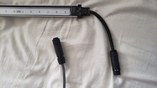
Figure 1: Wieland RST 16i2/3 connector is ideal for environments where moisture may be present, such as horticulture applications. (Source: Mouser)
Overview
The sensor and controller boards used in this project communicate back to the Xplained microcontroller board in two ways--either digitally utilizing a pulse width modulated signal or a 0V-5V analog signal that is read by the microcontroller’s Analog-to-Digital Converter (ADC).
- MIC3202 HB LED Driver: The MIC3202 has two control pins that operate at logic-level voltage. The first is the EN or ENABLE pin. This pin controls the output (-LED and +LED) being on or off. If the EN pin is drawn high, then power is delivered to the LED power wires. Conversely, if the EN is drawn to ground, the output voltage to the LEDs is cutoff, turning off any LEDs connected to the output.
The second pin, the DIM pin, controls the brightness of the LEDs. The DIM pin looks for a Pulse Width Modulation (PWM) signal to serve as the control signal for the LED brightness. Varying the duty cycle of the PWM signal will result in varying brightness-- 100% duty for full brightness and 0% to turn the LEDs off.
- TEMT6000 Ambient Light Sensor: This sensor acts like an NPN transistor with the base terminal controlled by the exposure to light. It is configured in a common collector amplifier circuit topology to allow for subtle changes at the input drive a larger output signal the CE junction to the microcontroller Analog-to-Digital (ADC) converter pin. The brighter the light, the more current and thus a higher voltage on the microcontroller ADC input pin.
Building the Electronics
The most important thing to keep in mind with this project is that we are dealing with AC mains. Safety is of paramount importance. Shock and fire are potential risks, so be conscious of the hardware and what is plugged in. Ensure the wires are insulated. Keep a fire extinguisher handy. Finally, check all the wiring connections twice before plugging the project into the AC wall outlet. Also note that I am in the United States, so everything I am using is for 120VAC, 60Hz mains. This will vary based on your geographical location.
Steps to assemble this project are as follows:
LRS 75-36 Switching Power Supply
- Take cable with a NEMA 15-5P plug on one end and expose the line (also referred to as hot), neutral and ground wire at the opposite end of the cable.
- Use a multimeter to verify which prongs on the plug correspond to which bare wires. Wire colors will vary from cable to cable, so don’t rely on images.
- Screw the line wire of the power cable to the socket marked “L” on the power supply.
- Screw the neutral wire of the power cable to the socket marked “N” on the power supply.
- Screw the ground wire of the power cable to the socket marked “G” on the power supply.
- Take a one-foot length of 16AWG two-wire outdoor lighting cable and strip both ends.
- Select one end of the cable and attach the white wire to the V+ socket of the power supply.
- Attach the black wire to the V- socket of the power supply.
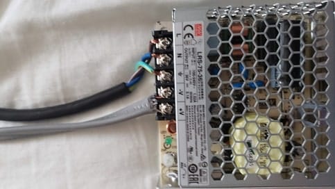
Figure 2: Power supply wired up. NEMA 15-5P on top, 16AWG outdoor lighting on bottom ran to the LED driver board. (Source: Mouser)
MIC3202 HB LED Driver Board
- Using the opposite end of the 16AWG two-wire outdoor lighting cable used in the previous section, solder the white wire to the VIN double turret solder terminal.
- Solder the black wire to the GND double turret solder terminal.
- Take a six-foot length of 16AWG two-wire outdoor lighting cable and strip both ends.
- Select one end of the cable and solder the white wire to the LED+ double turret solder terminal.
- Solder the black wire to the LED- double turret solder terminal.
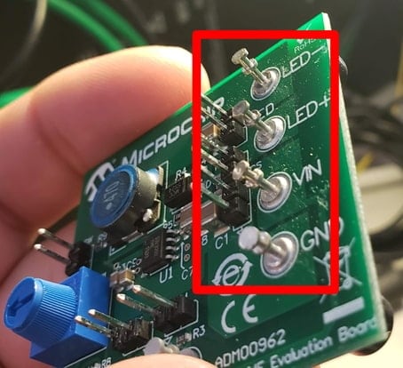
Figure 3: Double turret solder terminals. (Source: Mouser)
SAM W25 Xplained Pro Dev Board
- Connect the EN header pin on the MIC3202 board to pin 5 on the Xplained Pro Dev Board.
- Connect the DIM header pin on the MIC3202 board to pin 7 on the Xplained Pro Dev Board.
- Connect the GND header pin on the MIC3202 board to the GND pin on the Xplained Pro Dev Board.
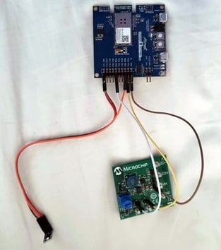
Figure 4: The SAM W25 board (top), TEMT6000 light sensor (bottom left), and LED driver board (bottom right). (Source: Mouser)
TEMT6000 Ambient Light Sensor
- Solder a 3-pin male header to the TEMT6000 breakout board.
- Connect the “V” header pin on the TEMT6000 board to the VCC pin on the Xplained Pro Dev Board.
- Connect the “G” header pin on the TEMT6000 board to the GND pin on the Xplained Pro Dev Board.
- Connect the “S” header pin on the TEMT6000 board to pin 3 on the Xplained Pro Dev Board.
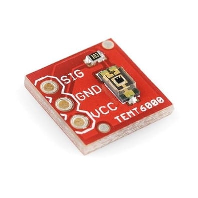
Figure 5: TEMT6000 ambient light sensor. (Source: Mouser)
LED Light Strip
- Find the opposite side of the six-foot length of 16AWG two-wire outdoor lighting cable coming off the MIC3202 board.
- Install the two exposed wires into the Wieland RST16i2/3 female connector.
- Connect the female side of the Wieland RST16i2/3 connector to the male Wieland RST16i2/3 connector found on the LED light strip.
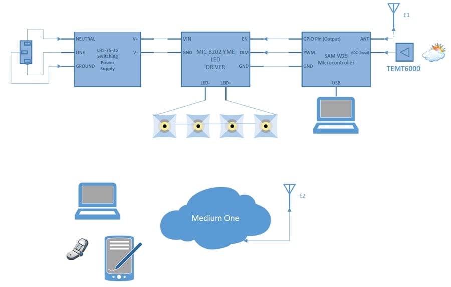
Figure 6: Functional block diagram of the project. (Source: Mouser)
Software
In this section, we will detail the software involved in this project. This will include the firmware and support files necessary for the Microchip Xplained board as well as the setup of the Medium One sandbox in your web browser. This source code provided for this project can be edited using Atmel Studio 7 or the Arduino IDE depending on your preference.
To use the Arduino IDE, Microchip provides the needed files on their GitHub site. The following URL will need to be added to the following location in the Arduino IDE: File > Preferences > Additional Boards Manager URLs. The URL is: https://github.com/AtmelUniversityFrance/atmel-samd21-xpro-boardmanagermodule/releases/download/v0.3.0/package_atmel-samd21-xpro-boardmanagermodule_0.3.0_index.json
The software for this project is divided across three parts.
- Microcontroller firmware is written in C.
- Cloud application to send and receive commands to/from the end users smartphone and the microcontroller. This code will be written in Python.
- Smartphone application provided by Medium One and will be configured specifically for this project.
Microchip Xplained Board Firmware
The firmware that runs on the microcontroller board is straightforward. The code does the following, in this order:
Setup
- Establish a serial debug connection to the host computer at 9600 baud.
- Attempt to connect the desired wireless network.
- Connect to the MQTT broker.
- Subscribe to the MQTT broker submit a topic for any messages sent from Medium One to the microcontroller.
- Set the various I/O pins as inputs or outputs.
Main Repeating Loop
- Poll the MQTT server with a heartbeat message to remain connected.
- Take a reading from the TEMT6000 ambient light sensor.
- Determine if the system is in manual or automatic mode.
- If in automatic mode, adjust the LED brightness by mapping the 0 to 1023 digitized brightness signal to a 255 to 0 value that will control the duty cycle of the PWM signal sent on the DIM pin.
- If in manual control mode, adjust the LED brightness by mapping the 0% to 100% setpoint set by the user on their smartphone to a 255 to 0 value that will control the duty cycle of the PWM signal sent on the DIM pin.
- Check to see if at least 1000ms has elapsed since the last message has been sent to the MQTT broker. If so, transmit a new message to the broker with the latest reading from the ambient light sensor.
Handle Any Messages Received from the MQTT Broker
- Print the received message onto the serial port.
- Convert the payload to a string.
- Determine if the string is requesting to toggle the manual control on or off; or if it is an integer that should be assigned as the manual brightness set point.
A quick note on the map function used in the project-- the function definition for the map is the following:
map(value, fromLow, fromHigh, toLow, toHigh)
The map function is very useful for re-mapping one range of numbers to another range of numbers. For example, the Analog-to-Digital (ADC) has a resolution of 1,024, whereas the analogWrite function only accepts values of 0 to 255. The map function takes 5 arguments including:
- The number to be scaled.
- The low-end of the range the number is being scaled from.
- The high-end of the range the number is being scaled from.
- The low-end of the range the number is being scaled to.
- The high-end of the range the number is being scaled to.
The map function returns an integer that has been re-mapped to the new scale. For example:
X = map(50, 1, 100, 1, 200);
In this case, x would be set to 100 because 50 is halfway between 1 and 100 on the old scale and 100 is in the middle of the new scale.
Project Files
This following files can be found in this https://github.com/Mouser-Electronics/MicrochipHorticultureLighting.
- MicrochipHorticultureLighting.ino: The project specific code for this effort is stored in this file. It is based upon an example that is provided by Medium One to demonstrate how embedded devices can interact with the IoT platform backend.
- secrets.h: When working on a project that is made publicly available, there is always a risk of exposing sensitive data such as passwords or API keys. Instead of hardcoding such information directly into the firmware and having to remember to alter the code prior to each Git commit, we can create an unpublished header file to store this information.
Libraries
The preprocessor directive #include lets us add libraries into our projects. This promotes code re-use. Unless you have very specific needs, re-inventing the wheel is not necessary. This project uses the following libraries:
- ArduinoMqttClient.h: This library provides a convenient interface to MQTT-based services.
- WiFi101.h: This library provides the interface to the ATWINC1500 chip to simplify interacting with Wi-fi networks.
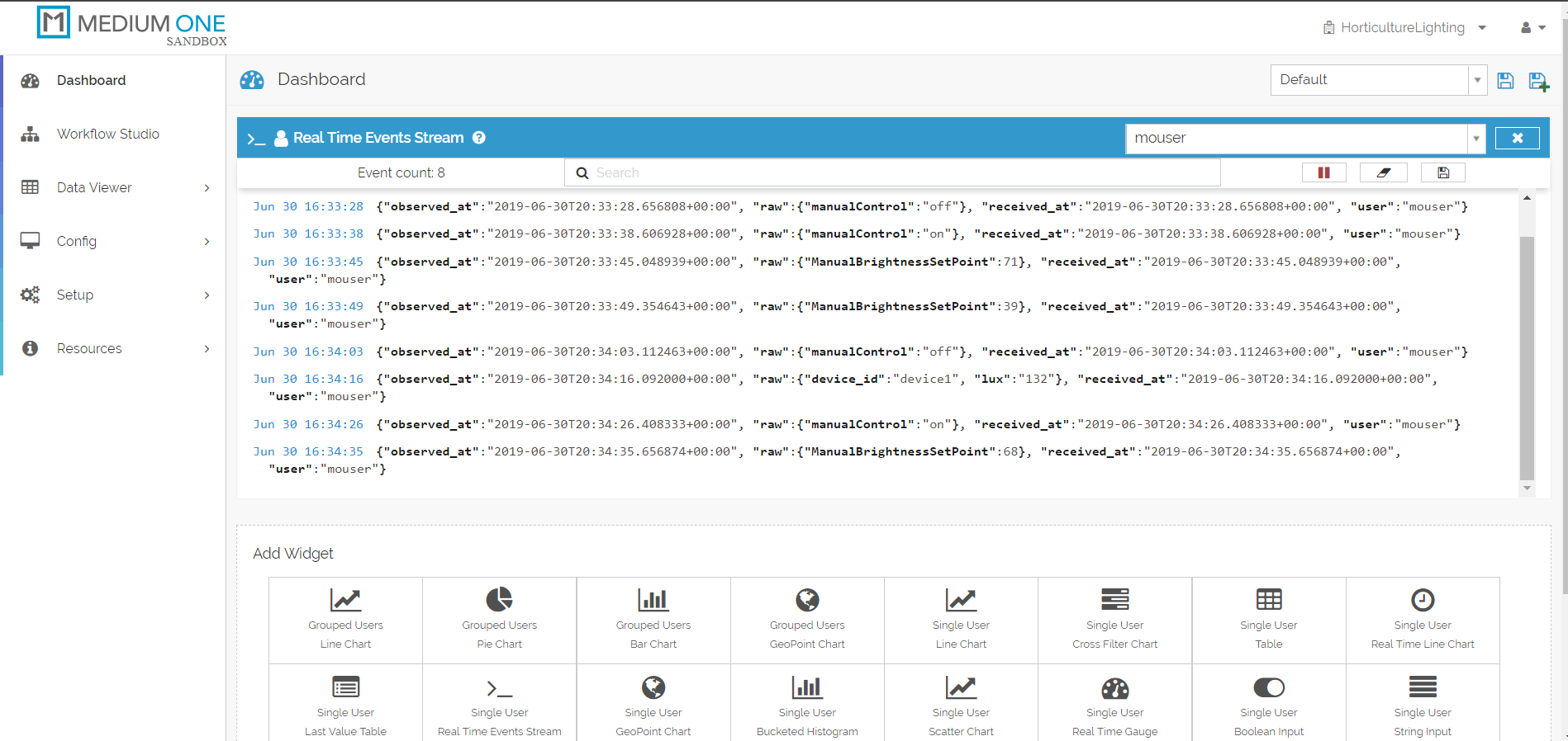
Figure 7: The raw data stream from the microcontroller and smartphone application. (Source: Mouser)
Variables and Constants
The first few variables are character arrays to store a variety of necessary information. First, are the SSID and WPA2 key to connect to the desired wireless network? Next, broker and port store the URL for the MQTT server and the TCP port it uses. Then, topic and subtopic store the URL paths and either receive data from or submit data to Medium One via an MQTT message. Lastly, the pubMessageStart and pubMessageEnd are the fixed portions of the message that will send the brightness reading to Medium One.
char ssid[] = SECRET_SSID
const char broker[] = SECRET_BROKER
const int port = SECRET_PORT
char pass[] = SECRET_PASS
const char topic[] = SECRET_TOPIC
const char subtopic[] = SECRET_SUBTOPIC
const char pubMessageStart[] = "{\"event_data\":{\"lux\":\""
const char pubMessageEnd[] = "\"}}"
Next, we have a few constants that are used to control the functions and interaction of the hardware.
- const int lightSensorPin = 3 Sets the ADC input pin for receiving the output signal from the TEMT600 light sensor
- const int DIMControlPin = 7 Sets PWM pin to an output that connects to the DIM pin on the LED driver board. Used to control the brightness of the LEDs.
- const int ENControlPin = 5 Sets GPIO pin to an output that connects to the EN pin on the LED driver board. Used to turn the output of the driver board on or off.
- const long interval = 1000 Sets the interval between transmissions to the Medium One server to 1000ms or 1 second.
Next, we have a few constants that are used to control the functions and interaction of the hardware.
- unsigned long previousMillis = 0 Tracks the timestamp from the last time a message was sent to the MQTT broker.
- unsigned int manualBrightSetPoint = 100 Stores the set point of the LED brightness level when in manual control mode.
- unsigned int setBrightPWM = 255 Stores the set point converted in the duty cycle value needed by the PWM pin connected to the DIM pin on the LED driver board.
- unsigned int sensorBrightnessReading = 0 Stores the most recent brightness reading taken from the TEMT6000 ambient light sensor.
- bool manualMode_ON = false A Boolean variable to track whether the user desires the system to be running in manual or automatic control mode.
Lastly, we have instantiations of the various classes we have included:
- WiFiClient wifiClient Creates an instance of the WiFi client class that lets the ATSAMD21G18A chip interact with the ATWINC1500 wifi chip and establish a connection to a Wi-Fi network.
- MqttClient mqttClient(wifiClient) Creates an instance of the MQTTClient class that lets the firmware interact with Medium One’s MQTT brokers through simple function calls.
Functions
- void setup(): The first function to run will initialize many of the hardware and software components needed such as the serial communications, Wi-Fi connection, sensor interface, and interactions with the GPIO pins.
- void loop(): This is the core of the functionality that will run continuously. Care is taken to ensure the main loop as minimal code and that functionality is handed off to specialized functions each responsible for individual tasks needed to make this project work.
- void onMqttMessage(int messageSize): This function handles any messages received from the Medium One server.
Configuring Medium One
Medium One provides IoT developers a platform where their IoT devices can communicate and compile data sets from across multiple IoT devices. They provide an excellent tutorial on getting started with their service, click here to learn more about Medium One. This guide will focus instead on the gotchas that we experienced in setting up the Microchip Xplained board to communicate with Medium One via their MQTT API. This project will leverage the Medium One’s MQTT (Message Queuing Telemetry Transport) protocol. MQTT is a publish-subscribe-based messaging protocol. It sits atop the TCP/IP protocol. MQTT, as opposed to RESTful APIs, requires a centralized message broker. Thus, endpoint devices cannot directly communicate with each other. This has pros and cons. Whereas RESTful APIs rely on the client to always initiate communications, MQTT allows a server to push data, thanks to the publish/subscribe (Pub/Sub) architecture. RESTful devices can communicate with each other directly. MQTT relies on a centralized message broker (e.g. a server in the cloud) and is much more efficient for transmitting this type of telemetry data.
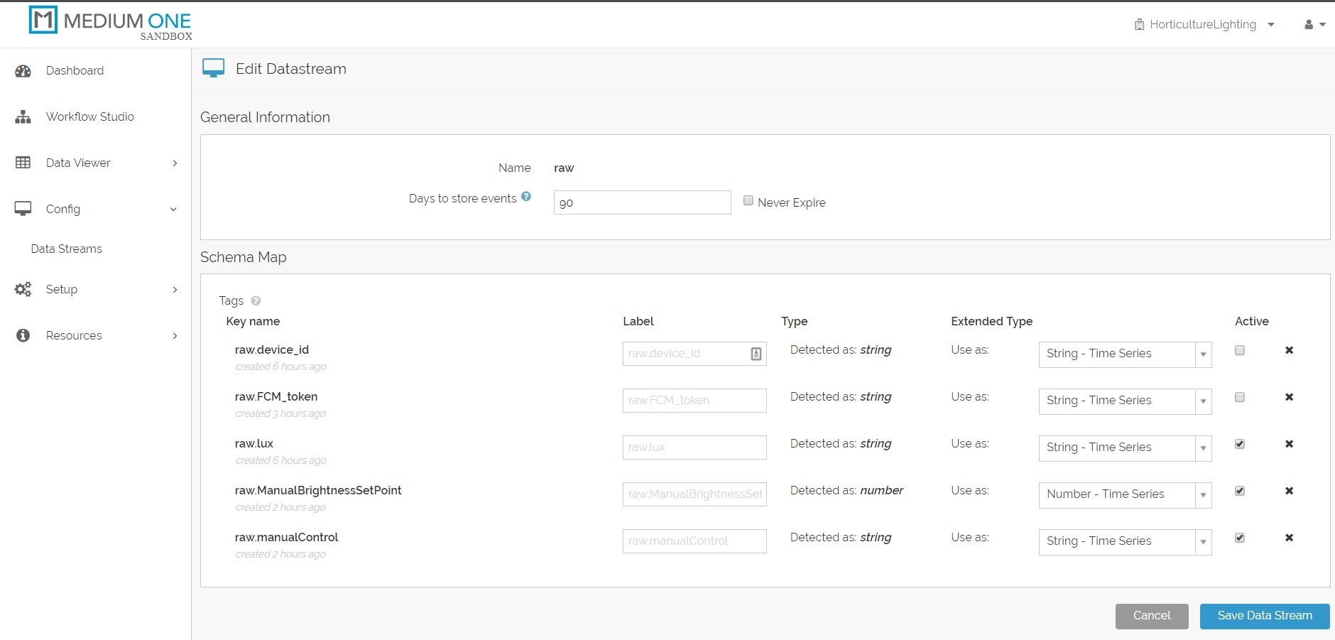
Figure 8: Configuration screen for Medium One. (Source: Mouser)
The first step is to create a free account at https://www.medium.one. Once you have your account, you will need to create a new project from the upper right corner of their web-based user interface.
After the new project is activated, it is necessary to make note of some crucial pieces of information that Medium One automatically generates for use back in the firmware (specifically, we will store this information in the secretstuff.h header file). The key pieces of information include:
- Project ID: This alphanumeric string is a unique identifier assigned to this specific project. It lets Medium One know what project to direct the Microchip Xplained board environmental data to if we have multiple projects hosted with their web service.
- API Key: This is an autogenerated alphanumeric string created to allow us to log in and use Medium One’s API services.
- MQTT ID: Each project can have multiple contributors. Note that the Login ID is not the same as the MQTT ID. The MQTT ID is an alphanumeric string generated by Medium One. The Login ID is an end user created, human-readable For example, “sallymsith”. The piece of information we need for the firmware is the MQTT ID and NOT the Login ID.
- User Password: This is created by each user when their account is established for the project. For security reasons, it is not displayed anywhere so be sure to remember this password!
Next, let’s determine where these pieces of information can be accessed from Medium One’s website:
- Setup -> Project Info: This will display the Project ID.
- Setup -> Manage Users: This is where the Login ID and the user’s MQTT ID can be found. Recall that it is the MQTT ID that is required for the firmware and not the Login ID.
- Setup -> Manage API Keys: This is to find the API Key.
Two other key pieces of information that the firmware will require are the Medium One MQTT server URL which is mqtt.mediumone.com. Also, the TCP port will either be 61619 (unsecured) or 61620 (secured). Lastly, we need to set up a dashboard to view if the data from the Microchip Xplained board is being received. To do that we will do the following:
- Go to the Dashboard and select the Single User Real-Time Events Stream option.
- Select the user you wish to view from the dropdown box.
- This should create the dashboard and start listening for data. If a green play button is visible ,then click it to begin listening. Otherwise, there will be a red pause button that can be used to pause the feed if so desired.
- If it works, then raw MQTT packets from the Microchip Xplained board should begin to be displayed in the browser. Ensure the Microchip Xplained board is powered via a USB connection to a computer or AC outlet wall wart power supply.
Cloud and Smartphone Applications
Medium One offers easy-to-use resources to create a basic smartphone app to interact with IoT devices. The aps are currently only available for iOS devices, but Android support is expected.
For this project, download the "IoT Controller" by Medium One for the Apple iOS App Store.
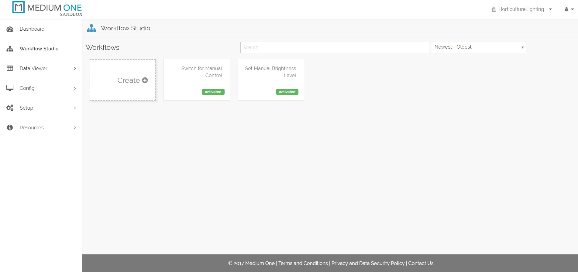
Figure 9: Medium One workflow studio. (Source: Mouser)
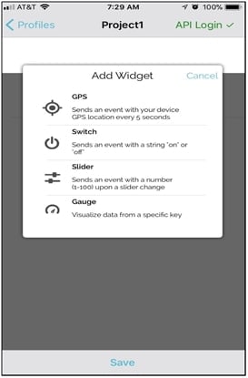
Figure 10: Adding new widgets to the smartphone application. (Source: Mouser)
For an in-depth, step-by-step tutorial for setting up the mobile app be sure to check out Medium One’s tutorials here. This section will highlight the unique things that are needed to be done for this particular project. Let’s start at adding a new widget to let the user control whether they want the lights in automatic or manual control mode.
- On the smartphone app, click +Add New Widget.
- Select Switch.
- Enter raw for the Stream.
- Enter “ManualControl” for the tag.
- Click Done.
- Click Save.
- Toggle the switch and look for messages to show up on Real Time Events Stream.
- Back on the desktop computer, from the Medium One dashboard click on Config > Data Streams > Raw.
- Ensure the Active checkbox is checked for the raw.manualControl tag.
- From the Medium One dashboard click on Workflow Studio > Create.
- Name it something similar to “Switch for Manual Control”
- On the right side of the screen, select Tags & Triggers > raw > manualControl and drag onto the studio screen.
- On the right side of the screen, select Modules > Foundation > Base Python and drag onto the studio screen.
- Double click the Base Python module and enter the following code under the Script section:
import MQTT
mode = IONode.get_input('in1')['event_data']['value']
if (mode == "on"):
MQTT.publish_event_to_client('device1', 'manualControl_ON', encoding='utf-8')
else:
MQTT.publish_event_to_client('device1', 'manualControl_OFF', encoding='utf-8')
- Press Save and Activate.
- Toggle the switch on the smartphone and verify that a message is being posted with a payload of manualControl_ON and manualControl_OFF .
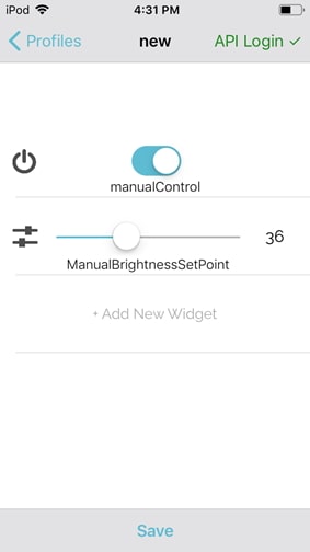
Figure 11: The finished user interface (UI) (Source: Mouser)
Next, lets create a slider to control the brightness of the LED.
- On the smartphone app, click +Add New Widget.
- Select Switch.
- Enter raw for the Stream.
- Enter “ManualBrightnessSetPoint” for the tag.
- Click Done.
- Click Save.
- Slide the switch up and down and look for messages to show up on Real Time Events Stream.
- Back on the desktop computer from the Medium One dashboard click on Config > Data Streams > Raw.
- Ensure the Active checkbox is checked for the raw.ManualBrightnessSetPoint tag.
- From the Medium One dashboard click on Workflow Studio > Create.
- Name it something similar to “Set Manual Brightness Level”.
- On the right side of the screen, select Tags & Triggers > raw > ManualBrightnessSetPoint and drag onto the studio screen.
- On the right side of the screen, select Modules > Foundation > Base Python and drag onto the studio screen.
- Double click the Base Python module and enter the following code under the Script section:
import MQTT
level = IONode.get_input('in1')['event_data']['value']
MQTT.publish_event_to_client('device1', str(level), encoding='utf-8')
- Press Save and Activate.
Toggle the switch on the smartphone and verify that a message is being posted with a payload of that will consist of a string value between 0 and 100 (integer).
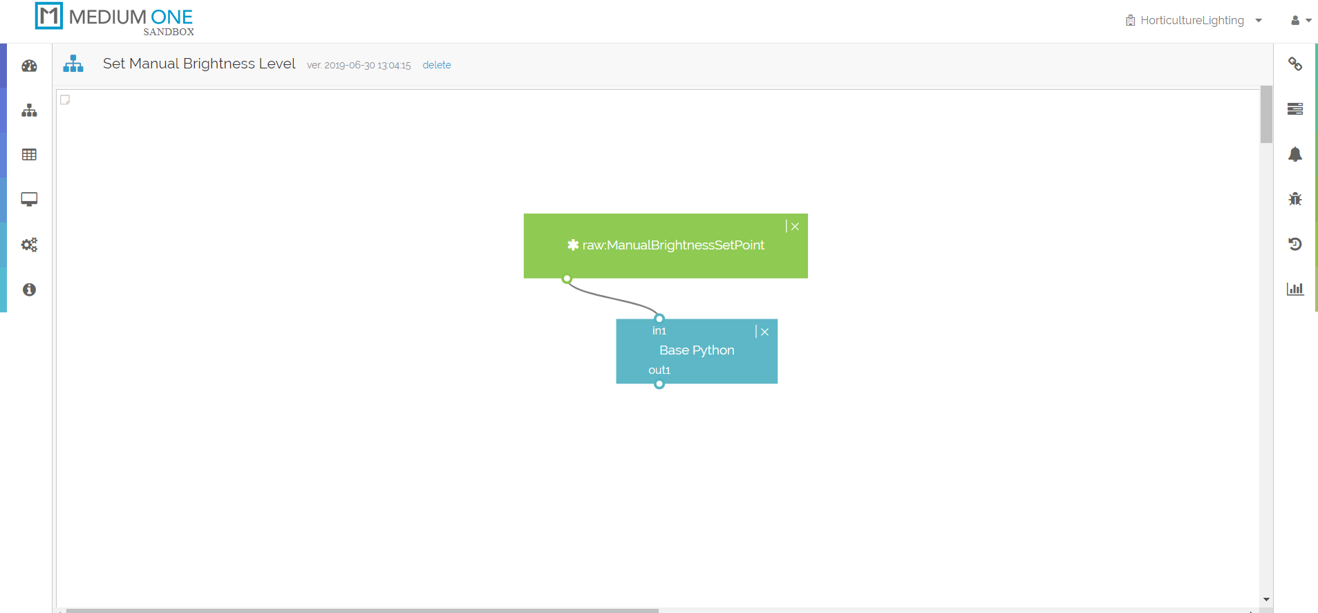
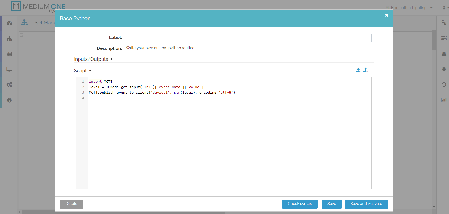
Figure 12a: The backend code to handle the smartphone interactions. Top: Setting manual brightness setpoint. Bottom: Turning manual mode on and off. (Source: Mouser)
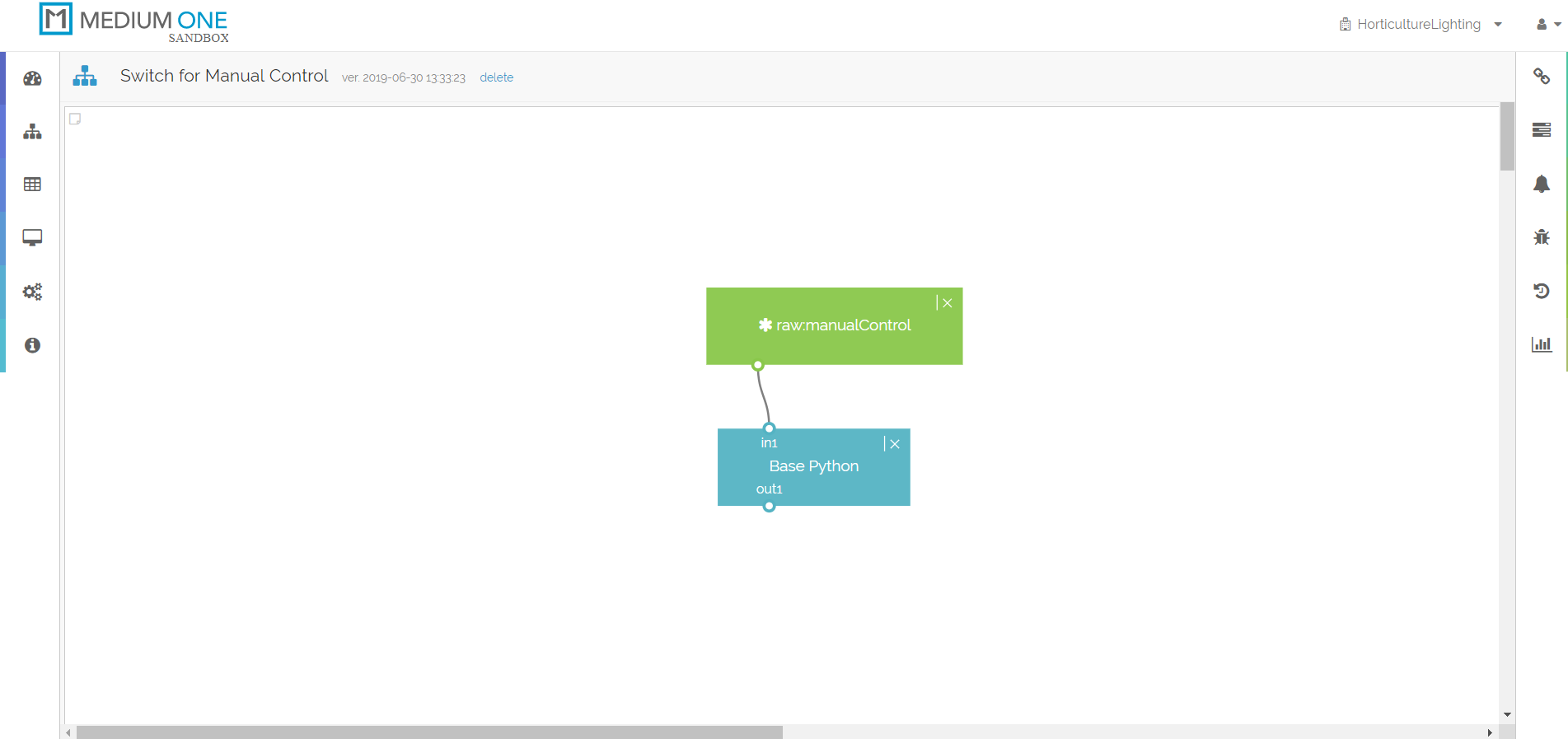
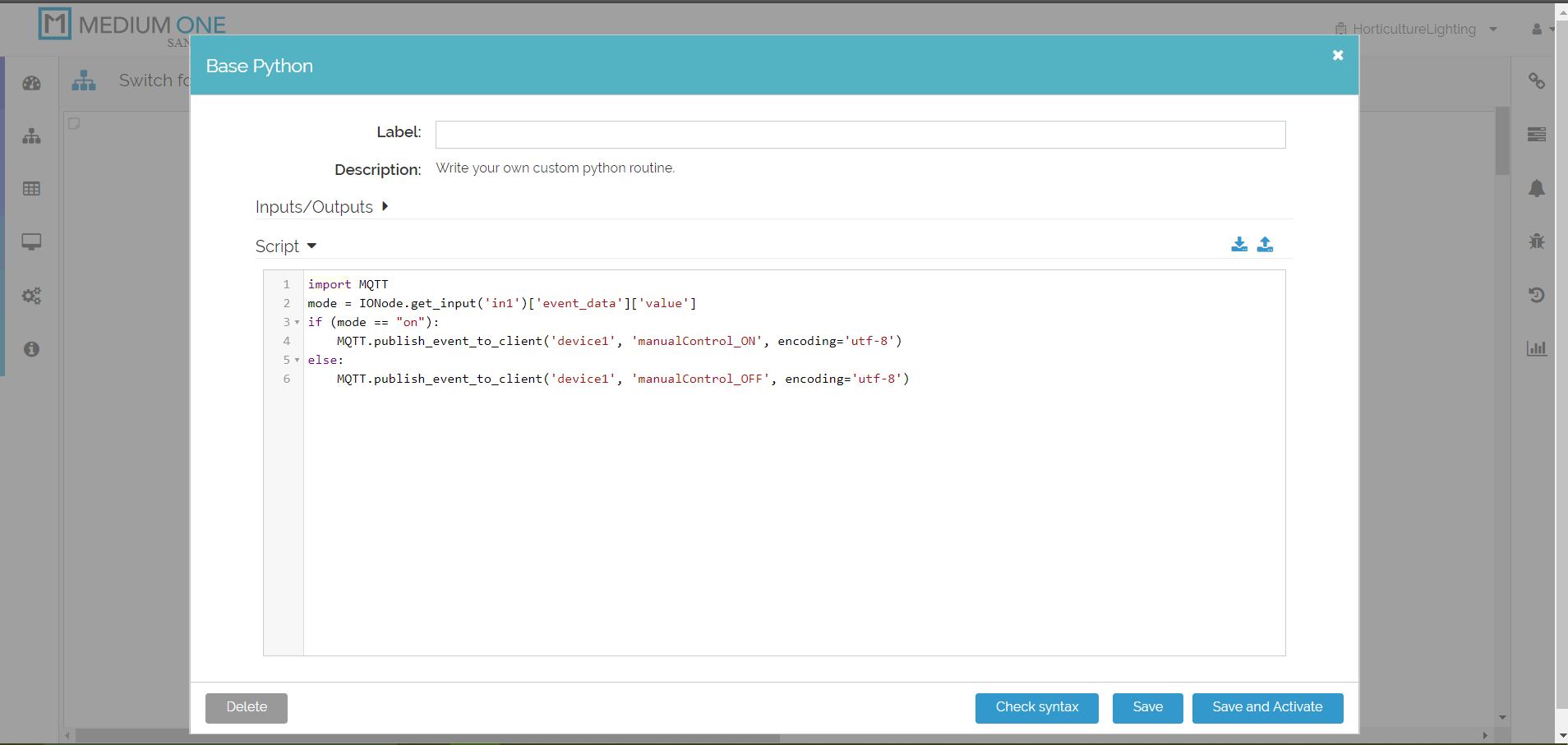
Figure 12b: Bottom: Turning manual mode on and off. (Source: Mouser)
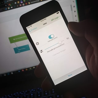
Figure 13: Using smartphone to control lighting. (Source: Mouser)
Project in Action
Once the project is assembled, hook up the Xplained board to a computer and fire up a serial terminal. You should telemetry from the light sensor flowing as well as MQTT messages to and from the Medium One MQTT broker. If not, check to see if there are any error messages. Some common errors include:
- Mixing up the line, neutral and ground wires feeding the power supply.
- Reversing the V+ and V- wires on the power supply or LED driver board.
- Reversing the LED- and LED+ wires on the LED light strip or the LED driver board.
- Reversing power and ground wires to sensors.
- If powering the device, ensure the power supply can deliver at least 1A of current.
The wireless network is not running, or SSID or security key was entered incorrectly.
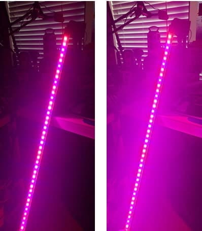
Figure 14: Left: Brightness at approximately 50% Right: Brightness at approximately 90%