Programmable LEDs Make Fire And Water
The Internet is chock-full of lighting ideas that use strings of battery-powered LEDs: Seasonal decor, patio camp “fires” and lamps, garden displays, and school projects, among many others. Although inexpensive and easy-to-use, many of these light strings are limited to being used indoors and require digging into the display to change the color and turn them on and off. While some units offer the convenience of an infrared (IR) remote, this can be a limiting factor if, for example, the unit is housed out of the direct line of sight—like inside the watering can—for aesthetics. The end result is either a constant hassle or something that isn’t used.
In this project, we’ll take a popular garden project—a lighted watering can (Figure 1)—and show you how to add functionality to a string of waterproof LED lights operated by an IR remote control. Whether you want to create this particular lighted watering can or apply the idea to different outdoor lighting project, the materials, code, and instructions provided here can be applied to various outdoor lighting projects where multi-color lights controlled with an easy-to-use app are the goal. This project comes complete with a Bill of Materials, a custom Arduino sketch, assembly instructions, and operating instructions.
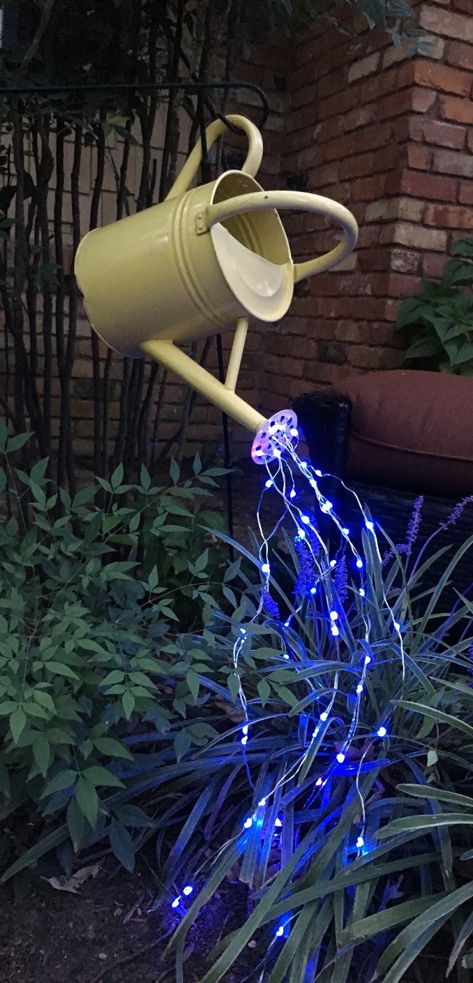
Figure 1: A watering can is a popular project that uses battery-powered LEDs. In this project, we extend the capabilities of the lights to provide multicolor functionality and to allow for remote control using a smartphone app.
We’ve geared this project toward DIYers with intermediate skills in working with electronics and computers. If you’re more of a gardening DIYer than an electronics DIYer—or if words like microcontroller and GitHub make you want to crawl under a rock—not to worry! You don’t need to understand the Design section provided here or the various technical explanations provided throughout; you can skip straight to the steps and complete this project. As long as you’re comfortable with downloading and installing software, understand the concept of storing files in a single directory, and have basic soldering and drilling skills, you’ll likely find that this project offers advanced functionality and a few learning opportunities while being manageable as well.
In the following sections, we start with an Overview, followed by these project phases:
- Gathering the Electronic Components
- Readying the Software
- Soldering the Components
- Assembling the Components
Overview
Project Level
This project is suitable for a curious intermediate-level DIYer with a few electronics projects to their credit. You will need to be comfortable with installing software such as Arduino IDE, installing board support packages, adding libraries from Github, and programming a board. This project also requires a bit of shop tool experience, including using a drill and a soldering iron.
Estimated Completion Time
- Planning and setup: 2 hours
- Computing work: 2 hours
- Assembly work: 2 hours
Description
In this project, we extend a popular lighted watering can project that is commonly created using a battery-operated string of single-colored lights that’s operated manually with an on/off switch and a multi-function remote control. The project goal is to enable a curious DIYer with some electronics and computing experience to use the more advanced lighting functions that are built-in to light strings available for purchase online. Completed projects will:
- Be appropriate for normal outside residential use
- Offer multiple light colors
- Offer color changing effects (e.g., red-green-blue)
- Be operable using a simple smartphone app
This project posed a few unique design challenges, including:
- Making the electronics relatively waterproof, and still able to charge easily
- Making the control box small enough to be hidden inside the watering can for aesthetics
- Designing an energy-efficient solution to minimize the need for charging
Design
The resulting design uses the Adafruit Bluefruit Feather M0 development board, which is thin and light while also providing the flexibility of the ATSAMD21G18 ARM Cortex M0 processor. There are prior iterations of this board that are simpler to setup, but they use the older and more power hungry ATMEGA32u4 for the primary processor. Adafruit, in partnership with Arduino, has done a great job in making this board easy and simple to setup and get started. There exists a well-written, easy-to-use library that can decode IR signals and allows them to be stored and sent out again, upon command, using a connected IR LED and allows the signals to be played.
The Adafruit Bluefruit BLE development platform includes a very user-friendly app that includes a Bluetooth LE UART interface, which is a very basic text only interface that communicates over Bluetooth. The UART interface allows a menu to be sent and letter/number commands to be sent back to the board to create an action, like turning on/off the lights or change the color. Bluetooth LE in this case is a very obvious choice, as it is not a line of sight communication protocol that has a usable range in excess of 30m and supports a wide variety of protocols.
This board includes a connector for a 3.7V Lithium battery, a battery management system that supports li-poly charging. The inclusion of the battery management system protects the lipo cell and allows for seamless switching to an input power source, when available, while starting a charging cycle for the battery. The inclusion of all the components for management means that a cell won’t be over-discharged and reduces external components, allowing a smaller, portable enclosure.
Additional electronics include a waterproof DC power connector jack and plug, which simplify one of the hardest parts of any outdoor design: Water resistance in an enclosure that you’ve drilled through to run power between the controller and power source. Another advantage of the Adafruit Feather platform is that it allows a voltage input up to 5.5VDC and includes a charging pin breakout, so an external charger can be used. This once again solves the problem of size and component count. Along with the Feather, these electronics are enclosed inside an IP54-rated polycarbonate box, which is attached under the top cover of the watering can (Figure 2).
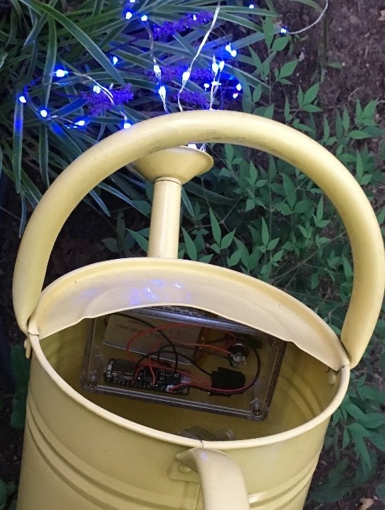
Figure 2: One of the design challenges was making the remote control work with the electronics hidden inside the watering can for aesthetics.
Step 1: Gather the Materials
This project assumes you have:
- A string of battery-powered programmable LEDs: Waterproof and Infrared Controllable are the two key features needed. Programmable “fairy lights” with an IP68 rating are good choices, and these often come with multi-color and chasing capabilities.
- A watering can: One with a partial covering on the top to obscure the control box is a good choice. We’re using a previously-loved tin watering can found at an antique shop, but a plastic can would work as well.
To complete this project, you’ll start by gathering:
- Electronic components
- Workshop tools
- Computing resources
Required Electronic Components
For easy access, we’ve bundled the electronics used in our watering can project into this handy Bill of Materials (BOM) at Mouser, as outlined in Table 1.
Table 1: For best results, we recommmed using the components we've gathered in the Mouser BOM.
Part Type |
The Mouser BOM Includes These Components |
|
An IP54 clear or opaque electronics enclosure |
|
|
A Bluetooth-ready microcontroller |
|
|
A 30V/5A sealed DC power connector power jack |
|
|
A power jack seal cap |
|
|
A 2.5mm DC power connector sealed plug |
|
|
An IR beam break sensor |
|
|
A 3.7V lithium battery |
|
|
A 7.5W/5V/1.5A AC wall-mount adaptor |
|
|
A micro-USB cable: Not included in the BOM, but needed if you don’t have one on hand. |
Although comparable components can be used, for best results, we recommend using those outlined here to ensure components work together and fit in the enclosure. Go ahead and order the components. While those are in transit, you can gather the required tools and complete Step 2.
Required Tools
While the electronic components are in transit, gather the required tools. Note that we recommend a high-speed step drill bit for drilling holes in the watering can nozzle:
- A flat work surface
- A multimeter
- A drill and
- A 1/8” drill bit or smaller
- A 7/18” high-speed step drill bit
- A soldering iron and 16- or 18-gauge tin solder
Minimum Computing Requirements
- Windows, Linux, or Mac OS with administrative access
- Internet access
- A micro USB cable
- An Android or iPhone
Step 2: Ready the Software
The Arduino Integrated Design Environment (IDE) is a very versatile tool that can program a wide array of boards; however, to minimize unnecessary downloads and space, the newest boards are not included by default, and must be configured. Additionally, the libraries, or the instruction sets, for how to use the functions of the modules must also be installed. After gathering the required materials, you’ll start by readying the software.
Code Overview
When a command is issued over Bluetooth, the microcontroller interprets it and transmits the corresponding command out through the IR LED as if the Remote had sent it. This simple task is easily accomplished by developing the Adafruit nRF callback example code, which allows single line variables to act as triggers for entry condition into sub-loops. This function allows minimal code writing and longer battery life as commands are not being sent into the ether.
Install and Set Up the Adafruit Microcontroller and Libraries:
- Go to https://learn.adafruit.com/adafruit-feather-m0-bluefruit-le/setup.
- Follow the instructions to download, install, and configure the Arduino IDE to be able to program the Adafruit Feather M0 processor. Be sure to install the Adafruit nRF51 Bluefruit LE Library as well.
- Go to GitHub and download this library: https://github.com/cyborg5/IRLib2.
- Unzip this file into the same library folder as the Bluefruit LE Library: ~/Documents/Arduino/libraries/.
- Restart Arduino to install the libraries.
Load the Custom Code
- Go to the Mouser Lighted Watering Can GitHub repository, Click the green “Clone or download” button and select “Download Zip”. From this Zip file, extract the folder named “Mouser_LightedWaterCan_1V0" and copy it into your Arduino folder located at ~/Documents/Arduino/.
- Open the Folder that was just extracted: Mouser_LightedWaterCan_1V0.
- Open the project file: Mouser_LightedWaterCan_1V0.ino.
Install the Bluefruit App
- Go to AppStore or Google Play on your smartphone and install the Adafruit Bluefruit app.
- Upgrade the nRF Chip Firmware, if the app prompts you. The minimum firmware revision is 0.7.0 when callback support was implemented.
Test the Custom Code
- Open the Adafruit app.
- Connect to “Adafruit Bluefruit LE.”
- Select UART. A list may populate in the UART window. If not, enter a number larger than 20 (and press Send) to prompt the menu setup.
- Ooo and Ahh over the color options provided in this custom code.
Step 3: Soldering the Components
Now that the board is programmed, the IR and charging components can be added to the system. The IR transmitter is all we need for the long term application of this project, as it is what will send the commands to the LED light string.
Pin Selection Explained
The IR library encodes the NEC IR transmission protocol onto the data selected, and it has a default output pin set to Pin 9.
As a side note, the selection of a IR transmitter is very important, as the Adafruit Feather runs at 3.3VDC with a pin output of 10mA, so any IR LED will need to be compatible with these power limits. Finally, the USB voltage pin of the LDO is broken out for the user to enable charging and/or external power operation. This pin will be connected to the positive pin of the waterproof power jack. Finally, the power supply will need to be modified to work with the waterproof power connector.
Simple Wiring
Figures 3 and 4 illustrate the needed solder connections.
IR Transmitter (the one with two wires)
- Solder the red wire to Pin 9.
- Solder the black wire to the GND pin.
Charging Wire
- Solder the charging wire to the USB pin.
GND Pin
- Twist the black wire of the IR transmitter and the GND/Shield wire of the power connector together.
- Solder the two wires to the GND pin.
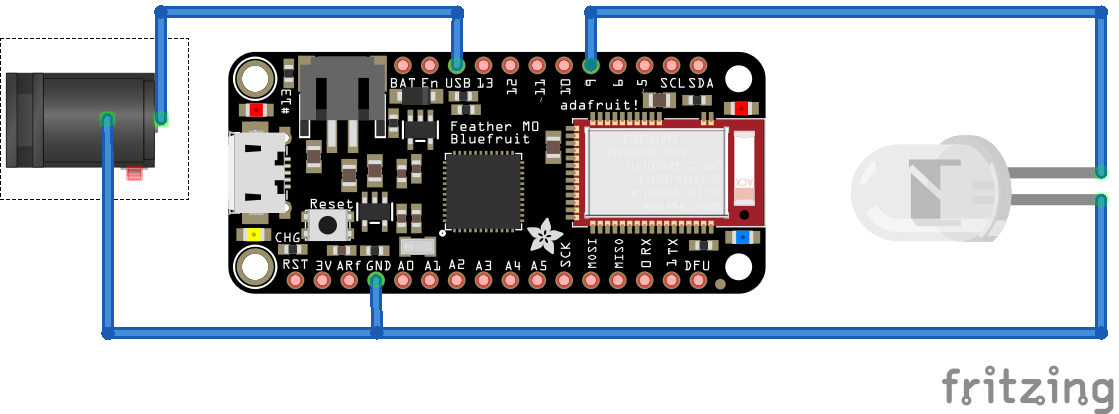
Figure 3: The Adafruit board with the IR transmitter wire, charging wire, and ground pin wire soldering completed. (Source: Fritzing)
Power Connector
- Remove the factory barrel jack from the cable with a pair of pliers or scissors.
- Strip ¼” of shielding off of the end of each of the two wires.
- Separate the two wires so there is plenty of room between them and tape them to a sturdy, non-conductive surface.
- Plug in the adapter.
- Using a multimeter, determine the wires’ polarity, ensuring the wires do not touch.
- Unplug the adapter.
- Solder the positive wire to the center pin of the waterproof barrel jack, and the negative to the shield.
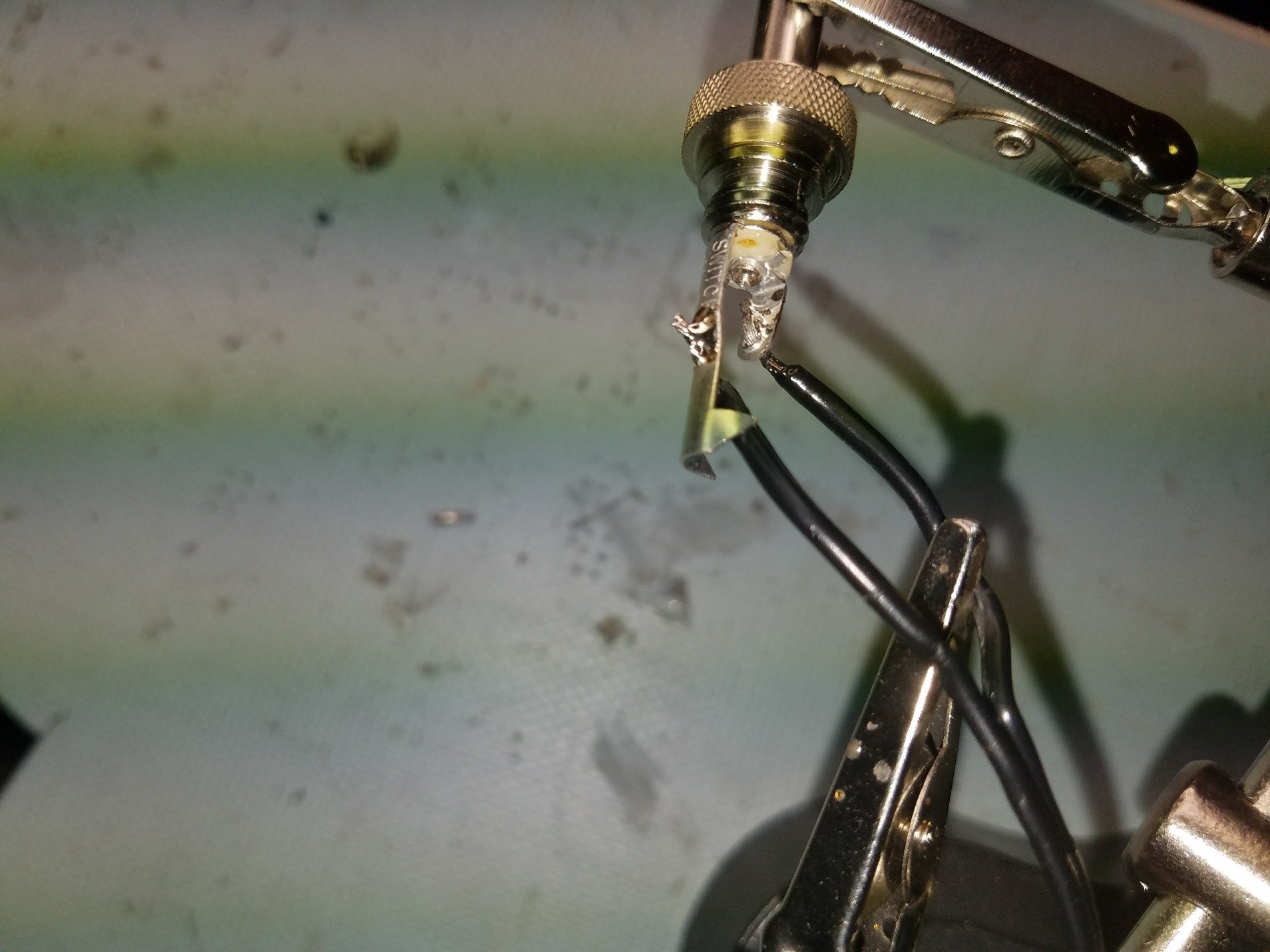
Figure 4: The soldered connector before completed assembly.
Step 4: Prepping and Assembling the Electronics Box
With the electronics soldered, prepare and assemble the water-resistant enclosure:
- Drill a pilot hole through the bottom of the box, centered width-wise and 1” from the end.
- Drill a 7/16” hole through the box. I recommend using a piece of Scotch tape at the stopping point of the drill bit to indicate where to stop drilling.
- Assemble the waterproof power connector (Figure 5): Starting with the box face down, take the waterproof power connector, place the o-ring around the shaft, push the connector through the hole. Place the round cap portion around the shaft, then metal washer, then the lock nut.
- Double-check power polarity before soldering. If the Power supply is backwards, adjust the wires already soldered to the Feather.
- Solder the power leads from the Feather to the power connector, with USB being connected to positive.
- Place the power connector alongside one side, battery on the bottom.
- Insert wires and make sure all parts fit inside with lid closed (Figure 6).
- Finally, insert the completed controller box on the underside of the watering can. We chose Velcro to attach the box to the watering can so that the box can be easily removed for charging.
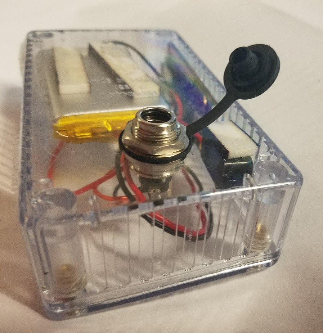
Figure 5: Assembling the waterproof connector.
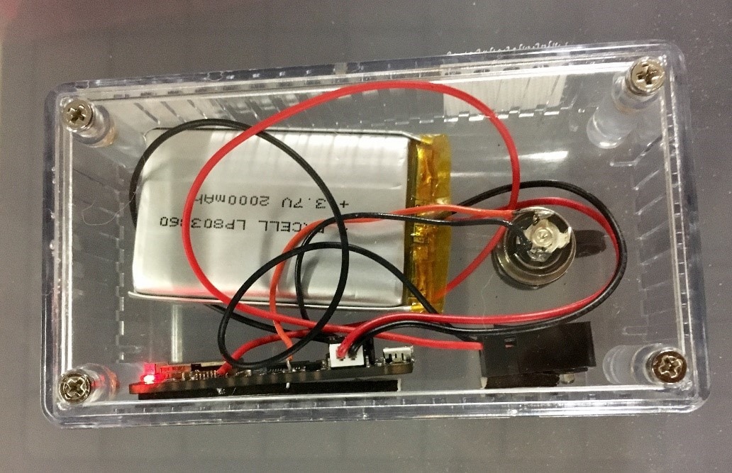
Figure 6: The completed electronics box, ready to be mounted under the top of the watering can.
Step 5: Install The Lights
- Ensure the holes are large enough on the watering can spout by attempting to push an LED through a hole. If the holes are too small, firmly clamp the watering can nozzle to a sturdy surface and use a stepper drill bit to enlarge the existing holes.
- Ensure the batteries are removed from the battery pack.
- If possible, remove the nozzle from the spout, if not already removed.
- Start the LED string through the watering can base into the spout.
- Pull the entire strand though the first hole, and reaffix the nozzle.
- In a looping fashion, run the LEDs through the holes in the nozzle, leaving the desired "waterfall" length each time.
- Install the batteries, and test that the lights work.
Step 6: Enjoy Your Lights
Ready to try out your new multi-color, remote-controlled watering can lights?
- Open the Adafruit app on your smartphone.
- Connect to “Adafruit Bluefruit LE.”
- Select UART. A list may populate in the UART window. If not, enter a number larger than 20 (and press Send) to prompt the menu setup.
- Change light colors by entering a color number and pressing Send. Table 2 Available light colors and their corresponding numbers.
- Change it again.
- And again.
- And again.
Table 2
Function or Color |
Number |
|
Off |
0 |
|
On |
1 |
|
Timer |
2 |
|
Red |
3 |
|
Green |
4 |
|
Blue |
5 |
|
Light Green |
6 |
|
Jade |
7 |
|
Mint |
8 |
|
Aqua |
9 |
|
Sky Blue |
10 |
Function or Color |
Number |
|
Cyan |
11 |
|
Dark Blue |
12 |
|
Lavender |
13 |
|
Violet |
14 |
|
White |
15 |
|
Fade (color to color) |
16 |
|
Jump (color to color) |
17 |
|
Reset (All Light settings) |
18 |
|
Brightness Up |
19 |
|
Brightness Down |
20 |
To charge the batteries, connect the waterproof power plug to the waterproof jack. I recommend doing any charging indoors, because the wall adapter recommended is not rated for outdoor use. When charging, a yellow LED will light up next to the Micro USB port and will turn off when finished. Currently the charge time has been around 8 hours.
We hope you enjoyed this project! Remember that you can use these programmable multi-colored lights for any number of outdoor, home, or school projects.
Show us your lighted watering can project or others you’ve done! Submit your project and photos in the comments.
Meanwhile, enjoy…and keep creating!