Getting Started with the PolarFire SoC FPGA Icicle Kit
By Mouser Staff
Published May 19, 2021
Introduction
RISC-V is one of the most interesting and hottest developments in the processor world now. RISC-V instruction set architecture is open source, so it is truly portable across platforms and customizable for a wide selection of applications ranging from robotics to medical imaging and beyond. Although many RISC-V solutions are available for FPGA implementations as soft-cores, the highest performance applications require a hard silicon implementation.
This is where the PolarFire® SoC Icicle Kit from Microchip Technology shines. The PolarFire System on a Chip (SoC) FPGA offers developers four 64-bit U54 RISC-V application cores along with an E51 monitor core, coupled with programmable logic. Both processor types can run at up to 666MHz. This combination offers developers the ability to optimize an ideal system response between the sequential processing of the RISC-V cores and the parallel structures of the programmable logic.
Bill of Materials
PolarFire SoC FPGA Icicle Kit

Figure 1: Microchip Technology PolarFire® SoC FPGA Icicle Kit (Source: Mouser Electronics)
To support the applications running on the RISC-V cores, the PolarFire SoC Icicle Kit provides:
-
DDR memory controller capable of supporting DDR4/DDR3/LPDDR4/LPDDR3
-
Integrated 128KB embedded Non-Volatile Memory (eNVM) for application / boot loader storage
-
Two GigE interfaces
-
USB On The Go (OTG)
-
QSPI controller with execute in place
-
SPI / UART / I2C / CAN
-
Timers and RTC
Connectivity between the processor and the programmable logic is implemented using protocols defined within by the Advanced Microcontroller Bus Architecture (AMBA). Communication between the programmable logic and the processors is implemented using:
- Two bi-directional 64-bit Advanced eXtensible Interface (AXI) buses
- One programmable logic to processor 64-bit AXI bus
- One processor to programmable logic 32-bit Advanced Peripheral Bus (APB).
The APB interface is used to configure IP blocks and control peripherals within the programmable logic while the AXI buses are used to implemented high-performance transfers of data between the processors and programmable logic using Direct Memory Access (DMA) structures.
The Icicle Kit is the first available PolarFire SoC development kit and provides developers a range of interfacing solutions from dual Ethernet to mikroBUS, CAN, RPi header, and PCIe. Memory-wise, the Icicle Kit provides a 2GB of LPDDR4 along with SPI Flash, eMMC, and an SD card for non-volatile application storage.
So, let’s discuss how to get started developing applications for the Icicle Kit, what software is needed, and how we update the reference applications provided by Microchip Technology.
Development Software
Like all field programmable gate array (FPGA) developments, we need several different EDA applications to move us from concept to final implemented solution. All of these are available to download from the Microchip Technology website. Microchip Technolgy has a wide array of videos available covering field-programmable Gate Arrays that can be found here
PolarFire SoC Microprocessor Subsystem Configurator
The MSS Configurator enables the configuration of the processor subsystem, the enabled peripherals, fabric interfaces, DDR configurations and clocking. The output of this is an XML file that can be imported by downstream FPGA and software implementation tools that customize the application development in line with the settings of the MSS. (Figure 2)

Figure 2: PolarFire SOC MSS Configurator (Source: Mouser Electronics)
Libero SoC
This is the FPGA implementation tool that takes the MSS configuration and imports the processor system definition. This allows the logic designer to connect custom RTL applications with the processor system. (Figure 3)

Figure 3: Libero SoC Design Suite (Source: Mouser Electronics)
SoftConsole
This is the software development environment that enables us to create bare metal solutions for the PolarFire SoC. SoftConsole also uses the MSS XML configuration to configure the application for the processor configuration. (Figure 4)

Figure 4: Microsemi SoftConsole Software Development Environment (Source: Mouser Electronics)
Within the processing system, the five processors are referred to as HARTs, with the E51 system supervision core being HART 0 and the quad U54 as HART 1- 4. Booting the system requires a boot loader unless the application is so small that it’s able to be stored in the eNVM.
For most applications, a boot loader is required. This is provided by the Hart Software Services (HSS). The HSS is provided on the PolarFire SoC GitHib and can be configured before use.
Installing and Customizing HSS
Once the HSS repository has been cloned, we can customize the HSS for a specific application using kconfiglib. If developing on a Windows machine, we need to install a couple of applications to enable support for kconfiglib before we can install and customize the HSS application. To be able to install support for kconfiglib on Windows, we need to first install MSYS2. (Figure 5)

Figure 5: MSYS2 Software Distribution and Building Platform for Windows (Source: Mouser Electronics)
Once MSYS2 has been installed, we are able to install the necessary packages using the MSYS terminal.
- pacman -S make python3 python3-pip
- pip3 install kconfiglib
- pacman -S gcc
- pacman -S libyaml libyaml-devel libelf libelf-devel zlib zlib-devel
With these tools installed, we can then run the HSS configuration tool using the command from within the HSS directory.
make BOARD=mpfs-icicle-kit-es config
Once the HSS is configured, we can import the project into SoftConsole and build the application. (Figure 6)

Figure 6: SoftConsole Project Import Screen (Source: Mouser Electronics)
The HSS can then be downloaded to the eNVM so that it will configure and boot the payload application from the selected non-volatile memory.
To create the payload application, we need to first compile and build the HSS payload generator. This application will take a YMAL file and generated ELF to create a BIN file that can be stored in the non-volatile memory and then loaded by the HSS that runs from the eNVM.
The YAML fine defines the entry points for each of the HART processors in the system. The HSS payload generator is built by running the Makefile within the HSS-payload-generator directory under the HSS cloned from the GitHub repository.

Figure 7: HSS Payload Generator (Source: Mouser Electronics)
The payload generator executable can then be copied under the test folder which contains example YAML files and ELF files with which to experiment. Calling the HSS payload generator from the command line is simple and only requires the YAML file and name of the output file. (Figure 7)
Hss-payload-generator.exe -c config.yaml output.bin
Bare Metal Software and SoC Configuration Tool
To be able to create bare metal applications that consider the configuration of the processor system, Microchip Technologies provides both bare metal libraries and an SoC configuration tool on GitHub. Along with the bare metal libraries, several example applications are also provided that demonstrate the operation of each peripheral (UART, timer and so on).
Having understood the constituent parts of the PolarFire SoC, let’s now look at a project creation and update walkthrough in detail.
Project Creation – Reference Design – TCL Flow
The easiest way to get up and running with a PolarFire SoC project is to use the existing Icicle reference design available on the Microchip GitHub. This reference design can be implemented using a TCL script that runs the MSS configurator in the background, before importing the MSS configuration into Libero and implementing the design. This can then be implemented and programmed into the PolarFire SoC. Once this has been completed, we are then free to download application software onto the processors to demonstrate that the flow is correct. One of the bare metal applications is a good choice.
Clone the Icicle reference design from the Microchip PolarFire SoC GitHub. (Figure 8).

Figure 8: Cloning a GitHub Repository (Source: Mouser Electronics)
- Open Libero 12.6 or greater and press ctrl-u to execute a script. (Figure 9)

Figure 9: Libero Script Execution (Source: Mouser Electronics)
- From the script file, selection navigate to the cloned directory and select the file ICICLE_KIT_eMMC.tcl and run the script.
- The script generation might take a few minutes to complete. Successful completion should be reported in the script execution report. (Figure 10)

Figure 10: Script Execution Report (Source: Mouser Electronics)
- The project should now be visible under the Design Hierarchy tab. You will notice the MSS system and additional blocks for the PCIe and clocks. (Figure 11)

Figure 11: Libero Design Hierarchy Tab (Source: Mouser Electronics)
- Connect the Icicle board to the Flash Pro 6 and power on the board. From the design flow, select run program This will generate a bit stream and program the device with the design and MSS configuration. (Figure 12)

Figure 12: Design Flow – Run Program action (Source: Mouser Electronics)
With the PolarFire SoC programmed, we are now in a position to download software applications to run on the processor cores.
- Clone the PolarFire bare metal library from the GitHub.
- Open SoftConsole, select a workspace and select import, and navigate to the just cloned library. This will import several examples into the SoftConsole workspace. (Figure 13)

Figure 13: SoftConsole Import Screen (Source: Mouser Electronics)
- Connect a USB cable to the J11 on the Icicle board. Open four UART terminals set for 155200, no parity, 1 stop bit.
- In SoftConsole, open the debug configurations from the main menu and select the mpfs-mmuart-interrupt-all-harts debug and click debug. This will download the application to the PolarFire SoC and halt the execution of the program at the start point. (Figure 14)

Figure 14: SoftConsole Debug Configuration Screen (Source: Mouser Electronics)
- The application will halt at the start of the e51 application in SoftConsole. Click on run to run the application and observe the output of the four terminals opened earlier. (Figure 15)

Figure 15: SoftConsole Interface Screen (Source: Mouser Electronics)
- One terminal will show a menu that displays a menu. Entering a command will result in other information being output on different UARTs. (Figure 16)

Figure 16: UART Output (Source: Mouser Electronics)
This section has demonstrated how we can recreate the reference design on the Icicle development board. Each of the bare metal applications can be run on the PolarFire SoC in the same manner.
Customizing the Design
Of course, real-world designs require different configurations to the reference design. Therefore, designers might need to make modifications to the system or include additional features in the fabric.
Let’s examine how we can customize the design by starting at the very beginning.
- Open the PolarFire MSS configurator tool.
- Open the MSS configuration cloned with the Icicle design. Select the PF_SoC_MSS_Icicle_eMMC.cfg file.
- This will open the configuration of the current MSS system. Explore the tabs and observe the settings (for example the GPIO, SPI settings etc.). (Figure 17)

Figure 17: MSS Configuration Screen (Source: Mouser Electronics)
- Deselect all interfaces except the UART interfaces. (Figure 18)

Figure 18: MSS Configuration Screen with UART deselected (Source: Mouser Electronics)
- Save the configuration with a new name and generate the output, identifying the directory to save the exported design.
- Open Libero 12.6 and create a new project targeting the MPFS250T_ES-FCVG484E component. (Figure 19)

Figure 19: Libero New Project Screen (Source: Mouser Electronics)
- When the project opens, select import MSS design from the design flow tab. Select the exported configuration from the MSS configurator. (Figure 20)

Figure 20: Selecting an Exported Configuration (Source: Mouser Electronics)
- Create a new smart design and give it a name.
- Select the MSS Import and choose the Instantiate in top level. (Figure 21)

Figure 21: Selecting Instanitiate in Libero (Source: Mouser Electronics)
- This will implement the MSS in the smart design. (Figure 22)
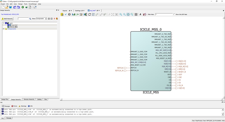
Figure 22: Libero Smart Design Window Populated with Current Project (Source: Mouser Electronics)
- Promote all the unconnected ports so they can be connected externally.(Figure 23)

Figure 23: Libero Smart Design Window Showing Promoted Ports (Source: Mouser Electronics)
- Configure the IO constraints. (Figure 24)

Figure 24: Configured IO Constraints (Source: Mouser Electronics)
- Implement and program the PolarFire SoC.
Creating a New SW Application
- Copy the XML file generated by MSS configurator under the reference directory of the PolarFire SoC configuration tool. Update the Bat / SH file to run the configuration SoC tool using the new XML file.
- Run the Bat / Sh file to generate the SoC configuration software files. (Figure 25)

Figure 25: Generating the SoC Configuration Software Files (Source: Mouser Electronics)
- In SoftConsole, create a new C Project and select RISC-V C Project. (Figure 26)

Figure 26: Creating a new RISC-V Project in SoftConsole (Source: Mouser Electronics)
- Select both configurations. (Figure 27)

Figure 27: Creating a new RISC-V Project in SoftConsole (Source: Mouser Electronics)
- Leave the tool chain as unchanged.
- From the cloned bare metal project, copy the platform directory under the SRC directory of the new project. Under the SRC directory, create additional directories of Application, Board/icicle-kit-es. (Figure 28)

Figure 28: Copying Files between Directories using File Explorer (Source: Mouser Electronics)
- Open the project settings and configure the Target Processor as below. (Figure 29)

Figure 29: SoftConsole Target Processor Selection in Project Settings (Source: Mouser Electronics)
- Set up the cross assembler include path as shown. (Figure 30)

Figure 30: SoftConsole PATH settings for Cross Assembler (Source: Mouser Electronics)
- Set up the C compiler as below. (Figure 31)
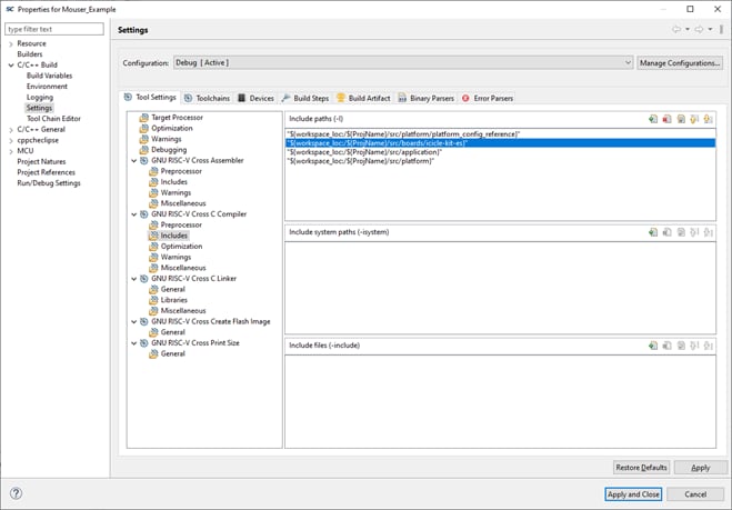
Figure 31: SoftConsole PATH Settings for C Compiler (Source: Mouser Electronics)
- Copy the SoC-Config directory created by the PolarFire SoC configuration tool under the project/src/boards/icicle-kit-es directory. (Figure 32)

Figure 32: SoC Config Directory Location (Source: Mouser Electronics)
- Copy across the application directory from the mpfs-mmuart-interrupt example into the new project.
- Build the application. This should create an ELF file. (Figure 33)

Figure 33: ELF file generated after successful build (Source: Mouser Electronics)
- With the ELF file available, we can now download and run the application on the board. To do this, we need to create a debug configuration. Open the debug configuration tab and create new configuration. Select the ELF file just created. (Figure 34)

Figure 34: SoftConsole Debug Configuration Tab (Source: Mouser Electronics)
- Ensure the settings are as below on the debugger settings tab. (Figure 35)

Figure 35: SoftConsole Debug Configuration Debugger Settings (Source: Mouser Electronics)
- Finally, ensure the set breakpoint is set to the function e51 on the start-up tab. (Figure 36)

Figure 36: SoftConsole Debug Configuration Startup Tab (Source: Mouser Electronics)
- Click on debug and the application will download to the target and run.
Wrap Up
Here, we have introduced the tool chains that are used for the development of the PolarFire SoC microprocessor and fabric. Recreating the existing reference design can be quickly and easily achieved using the provided TCL scripts. These scripts are a great starting point to begin creating custom applications as this walkthrough has shown.